EP0043539A2 - Drosseldruckregelventil für Getriebe - Google Patents
Drosseldruckregelventil für Getriebe Download PDFInfo
- Publication number
- EP0043539A2 EP0043539A2 EP81105058A EP81105058A EP0043539A2 EP 0043539 A2 EP0043539 A2 EP 0043539A2 EP 81105058 A EP81105058 A EP 81105058A EP 81105058 A EP81105058 A EP 81105058A EP 0043539 A2 EP0043539 A2 EP 0043539A2
- Authority
- EP
- European Patent Office
- Prior art keywords
- valve
- pressure
- throttle
- sleeve
- opening
- Prior art date
- Legal status (The legal status is an assumption and is not a legal conclusion. Google has not performed a legal analysis and makes no representation as to the accuracy of the status listed.)
- Ceased
Links
Images

Classifications
-
- F—MECHANICAL ENGINEERING; LIGHTING; HEATING; WEAPONS; BLASTING
- F16—ENGINEERING ELEMENTS AND UNITS; GENERAL MEASURES FOR PRODUCING AND MAINTAINING EFFECTIVE FUNCTIONING OF MACHINES OR INSTALLATIONS; THERMAL INSULATION IN GENERAL
- F16H—GEARING
- F16H61/00—Control functions within control units of change-speed- or reversing-gearings for conveying rotary motion ; Control of exclusively fluid gearing, friction gearing, gearings with endless flexible members or other particular types of gearing
- F16H61/02—Control functions within control units of change-speed- or reversing-gearings for conveying rotary motion ; Control of exclusively fluid gearing, friction gearing, gearings with endless flexible members or other particular types of gearing characterised by the signals used
- F16H61/0262—Control functions within control units of change-speed- or reversing-gearings for conveying rotary motion ; Control of exclusively fluid gearing, friction gearing, gearings with endless flexible members or other particular types of gearing characterised by the signals used the signals being hydraulic
- F16H61/0276—Elements specially adapted for hydraulic control units, e.g. valves
- F16H61/029—Throttle valves
-
- Y—GENERAL TAGGING OF NEW TECHNOLOGICAL DEVELOPMENTS; GENERAL TAGGING OF CROSS-SECTIONAL TECHNOLOGIES SPANNING OVER SEVERAL SECTIONS OF THE IPC; TECHNICAL SUBJECTS COVERED BY FORMER USPC CROSS-REFERENCE ART COLLECTIONS [XRACs] AND DIGESTS
- Y10—TECHNICAL SUBJECTS COVERED BY FORMER USPC
- Y10T—TECHNICAL SUBJECTS COVERED BY FORMER US CLASSIFICATION
- Y10T137/00—Fluid handling
- Y10T137/8593—Systems
- Y10T137/86493—Multi-way valve unit
- Y10T137/86574—Supply and exhaust
- Y10T137/8667—Reciprocating valve
- Y10T137/86694—Piston valve
- Y10T137/8671—With annular passage [e.g., spool]
Definitions
- My invention comprises improvements in a throttle valve system for an automatic transmission such as that described in U.S. patent Nos. 3,327,554 and 4,008,630.
- Each of these patents discloses an automatic transmission having planetary gear elements that establish plural torque delivery paths between an internal combustion engine and a driven member, the traction wheels for the vehicle being connected to the driven member through a differential and driveshaft mechanism.
- a positive displacement pump driven by the engine establishes a control circuit pressure in control systems of the type disclosed in these references.
- the control circuit forms a connection between the pump and fluid pressure operated clutches and brakes that in turn control the relative motion of the gear elements of the mechanism thereby establishing a desired torque ratio.
- the control circuit includes shift valves that control distribution of control pressure selectively to the clutches and brakes of the transmission whereby automatic ratio changes can be achieved.
- the shift valves respond to a speed signal made available by a fluid pressure governor driven by the driven shaft and to a torque demand pressure signal developed by the throttle valve mechanism.
- the throttle valve mechanism influences the shift points during operation of the mechanism at varying speeds and road loads.
- the control valve circuit includes also a pressure regulator that establishes the desired control pressure level. Provision is made for decreasing the magnitude of the regulated circuit pressure for any given torque demand as the vehicle speed increases. Provision is made also for increasing the regulated pressure made available by the regulator
- My 'invention comprises improvements in a throttle valve system for an automatic transmission such as that described in U.S. patent Nos. 3,327,554 and 4,008,630.
- Each of these patents discloses an automatic transmission having planetary gear elements that establish plural torque delivery paths between an internal combustion engine and a driven member, the traction wheels for the vehicle being connected to the driven member through a differential and driveshaft mechanism.
- a positive displacement pump driven by the engine establishes a control circuit pressure in control systems of the type disclosed in these references.
- the control circuit forms a connection between the pump and fluid pressure operated clutches and brakes that in turn control the relative motion of the gear elements of the mechanism thereby establishing a desired torque ratio.
- the control circuit includes shift valves that control distribution of control pressure selectively to the clutches and brakes of the transmission whereby automatic ratio changes can be achieved.
- the shift valves respond to a speed signal made available by a fluid pressure governor driven by the driven shaft and to a torque demand pressure signal developed by the throttle valve mechanism.
- the throttle valve mechanism influences the shift points during operation of the mechanism at varying speeds and road loads.
- the control valve circuit includes also a pressure regulator that establishes the desired control pressure level. Provision is made for decreasing the magnitude of the regulated circuit pressure for any given torque demand as the vehicle speed increases. Provision is made also for increasing the regulated pressure made available by the regulator
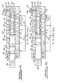
- the impeller, the turbine and the stator are arranged in toroidal fluid flow relationship in known fashion, the stator 18 being mounted on a one way coupling 22 which prevents rotation of the stator in a direction opposite to the direction of rotation of the impeller but permits rotation in the direction of rotation of the impeller.
- Crankshaft 10 is connected to a positive displacement pump 24 through a central shaft 26, the pump 24 serving as a pressure source for the control system to be described with reference to Figure 3.
- a first torque input shaft 28 in the form of a sleeve surrounds the shaft 26.
- a second torque input shaft 30 in the form of a sleeve surrounds the shaft 28.
- a simple planetary torque splitter gear unit 32 is located in the converter drive shell 20 and it includes a ring gear 34, a sun gear 36, a carrier 38 and planet pinions 40 journalled rotatably on the carrier 38 and meshing with ring gear 34 and sun gear 36.
- Input sleeve shaft 28 is connected to the carrier 38 and input sleeve shaft 30 is connected to sun gear 36.
- the main multiple ratio gearing for the mechanism of Figure 1 is a compound planetary gear set 40 which comprises ring gear 42, a small pitch diameter sun gear, a large pitch diameter sun gear 46, ' a compound planet carrier 48, long planet pinions 50, and short planet pinions 52, the carrier 48 journalling rotatably the pinions 50 and 52.
- Sun gear 46 drivably engages pinions 50
- ring gear 42 drivably engages pinions 52 as well as ring gear 42.
- Pinions 52 also engage sun gear 44.
- a first clutch 54 which also carries the symbol CL 1 , is adapted to connect selectively sun gear 44 and sleeve shaft 30.
- Clutch 54 is actuated by a servo which will be described briefly with reference to Figure 3.
- An overrunning coupling 56 is located in parallel disposition with respect to the clutch 54 and establishes a one way driving connection between shaft 30 and sun gear 44 during operation in the first forward driving ratio.
- a second friction clutch 58 is adapted to connect selectively sleeve shaft 28 and ring gear 42. It is applied during second speed ratio operation and during third speed ratio operation. It is operated by a clutch servo as will be described briefly with reference to Figure 3.
- Friction brake 60 is designated in Figure 1 by reference symbol CL 3 and friction 58 is designated in Figure 1 by symbol CL 2 .
- a friction brake band 64 is adapted to brake selectively large diameter sun gear 46. During first speed ratio operation and second speed ratio operation it is applied and released by a fluid pressure operated servo as will be described briefly with reference to Figure 3.
- a final drive and transfer gear mechanism is located between the compound planetary gearing 40 and the hydrokinetic torque converter 12 as indicated generally by reference character 66.
- a torque output sleeve shaft 68 connects the carrier 48 with a final drive input gear 70.
- a fixed idler 72 is mounted for rotation about a fixed axis so that it engages gear 70 as well as final drive output gear 74.
- Gear 74 in turn may be connected through a speed reduction gear and a differential and axle mechanism to each of two axle shafts in the automotive vehicle driveline.
- Figure 2 I have shown a chart that summarizes the clutch and brake engagement and release pattern for the clutches and brakes shown schematically in Figure 1.
- the symbols B 1 , CL 1 , CL 2 , CL 3 and OWC designate the clutches and brakes that have corresponding symbols in Figure 1.
- the left hand column of Figure 2 shows the three ratios that are available in a first drive range D, the two drive ratios available for the drive range "2" and the single ratio that is available during drive range "1".
- the clutches and brakes are arranged horizontally in Figure 1 and the symbol "X" in each instance designates a clutch or brake engagement while a blank space designates a clutch or brake release condition.
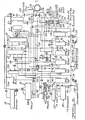
- FIG 3 I have designated very generally the principal elements of the control circuit for controlling the engagement and release of the clutches and brakes of Figure 1.
- the pump 24, as seen in Figure 3, supplies the main oil pressure regulator valve assembly 76 which establishes a regulated pressure level in the control circuit.
- the low speed brake 64, the intermediate clutch 58, the direct clutch 54 and the reverse brake 60 are supplied with fluid pressure from the pump 24 which is regulated by the regulator valve 26 through the various passages illustrated schematically in Figure 3.
- a governor valve assembly 78 driven by the shaft 68 supplies a speed signal pressure to the control system. That pressure is distributed through passages to a 1-2 shift valve 80 and a 2-3 shift valve 82 as well as to the various shift timing valves including the 3-2 shift timing valve 84 and the 3-2 coast control valve 86.
- a 3-2 downshift control valve 88 responds to throttle pressure to control the timing of the 3-2 downshift.
- the 2-3 upshift point is controlled in part by the operation of a 2-3 modulator valve 90.
- a 1-2 capacity modulator valve 92 controls the timing of the 1-2 upshift and the capacity of the intermediate clutch servo during the upshift mode. The 1-2 capacity modulator valve acts in cooperation with the 1-2 accumulator valve 94 to establish that function.
- Manual valve 96 receives pressure from the pump 24 and distributes it to the various control circuit regions.
- the regulator valve 76 receives output pressure from the pump 24 through passage 98. It comprises a regulator valve spool 100 having multiple lands that register with internal lands formed in a regulator valve bore 102. Passage 98 includes a feedback branch passage portion 104 which communicates with one side of the valve spool 100 to develop a pressure that opposes the force of the valve spring 106.
- a pressure booster valve element 108 located in the lower portion of the valve bore 102 includes multiple lands which establish three pressure areas which are identified in Figure 3 by reference numerals 110, 112 and 114, the pressure area 110 being subjected to a torque demand sensitive throttle pressure distributed to it through passage 116.
- the area 112 is subjected to a torque demand sensitive throttle pressure during reverse drive operation, the pressure being distributed to it through passage 118 which extends to reverse boost valve 120.
- Valve 120 establishes a connection between passage 118 and the throttle valve assembly 122 during reverse drive.
- An auxiliary pressure is distributed to area 114 through passage 124 when the manual valve 96 is moved to the reverse drive position so that an additional increase in regulated line pressure occurs during reverse drive.
- Valve spool 100 establishes controlled communication between line pressure passage 98 and exhaust port 126 during its pressure regulation mode, the exhaust port 126 communicating with the converter inlet passage.
- the fluid pressure operated brake servo for operating the brake 64 and the clutch servos for operating the clutches 54 and 58 may be similar to the clutches and brakes described in prior art patent No. 3,327,554 mentioned previously in this specification.
- Clutch pressure for the clutch 58 is distributed through passage 128 and actuating pressure for the third speed ratio clutch 54 is distributed through passage 130.
- the servo for the brake 64 receives actuating pressure through passage 132 and it receives brake release pressure through passage 134.
- Throttle pressure developed by the throttle valve assembly 122 is distributed through passage 136 to a pressure limit valve 138. This establishes a maximum value for the throttle pressure.
- the throttle pressure is distributed to the 1-2 shift valve 80 through the passage 140.
- a modulated 2-3 shift delay pressure is distributed through passage 142 to the 2-3 shift valve 82 from the 2-3 modulator valve 90.
- the passage 128 which feeds the clutch 58 receives its actuating pressure from the 1-2 capacity modulator valve 92 which is supplied with circuit pressure from the 1-2 shift valve.
- the 1-2 accumulator 94 controls the timing of the application of the clutch 58 when the 1-2 shift valve is stroked to the upshift position.
- the throttle valve assembly 122 controls both the shift points and the regulated circuit pressure.
- the influence of the throttle pressure on the shift valve is opposed by governor pressure made available to each of the shift valves 80 and 82 by the fluid connection 144 which extends to the governor 78.
- the calibration of the throttle valve assembly therefore, is of importance because of its effect on shift timing as well as its effect on the roughness or harshness of the ratio shifts.
- the improvement of my invention makes it possible to establish the desired throttle pressure for any given vehicle installation so that the shift points will occur at the proper instant and so that the shift quality will be optimum.
- the throttle valve assembly 122 includes the valve body 146 having a valve bore 148 in which is positioned a throttle plunger 150.
- the plunger 150 comprises two valve lands 152 and 154, the latter being smaller than the former so that a differential area is established between the lands.
- Land 154 is slidably received in a sleeve 156 located at one end of the valve bore 148.
- the outboard end of the land 154 is adapted to be connected to the engine carburetor throttle linkage through a suitable motion transmitting device which may include a roller cam follower 160 that is adapted to engage a driver controlled cam actuator, not shown.
- a suitable motion transmitting device which may include a roller cam follower 160 that is adapted to engage a driver controlled cam actuator, not shown.
- a regulating valve element 162 is located on the right hand side of the plunger 150 and is slidably received in a valve sleeve 164.
- a throttle valve spring 167 connects the plunger 150 with the valve element 162, movement of the plunger 150 upon advancement of the engine carburetor throttle causing an increase in the spring compression force which is transmitted in turn to the valve element 162.
- Valve ' element 162 comprises two spaced valve lands 166 and 168. These register with line pressure port 170 and exhaust port 172, respectively.
- a throttle valve pressure outlet port 174 in the sleeve 164 communicates with the interior of the sleeve between lands 166 and 168.
- a throttle pressure feedback port 176 formed in the sleeve 164 communicates with a throttle pressure feedback chamber 178 on the right hand end side of the land 168.
- Sleeve 164 has a closed right hand end 180 which defines a cone surface 182. This cone surface is engaged by one end of a threaded adjusting member or set screw 184 which is received threadably in opening 186 of the valve body 146.
- the outboard end 188 of the set screw 184 is adapted to be engaged by a hand tool such as a screwdriver so that the set screw 184 can be adjusted inwardly and outwardly and then locked in place by a lock nut 190. Because of the camming action between the end of the set screw 184 and the cone surface 182, the sleeve 164 is adjusted axially.
- Movement of the set screw 184 inwardly causes leftward adjustment of the sleeve 164 and, conversely, movement of the set screw outwardly causes movement of the sleeve 164 in a right hand direction under the influence of throttle pressure in the chamber 178.
- Throttle pressure ports 176 and 174 are connected to the previously described passage 136. Line pressure is distributed to the throttle valve assembly through passage 192 to the port 170.
- the modulating characteristic of the throttle valve assembly can be changed by appropriately adjusting the set screw 188.
- a reduced throttle pressure for any given setting occurs as the sleeve 164 is shifted in a right hand direction upon adjustment of the set screw 184.
Landscapes
- Engineering & Computer Science (AREA)
- General Engineering & Computer Science (AREA)
- Mechanical Engineering (AREA)
- Control Of Transmission Device (AREA)
- Multiple-Way Valves (AREA)
Applications Claiming Priority (2)
| Application Number | Priority Date | Filing Date | Title |
|---|---|---|---|
| US06/165,883 US4369677A (en) | 1980-07-03 | 1980-07-03 | Transmission throttle pressure regulator assembly |
| US165883 | 1980-07-03 |
Publications (2)
| Publication Number | Publication Date |
|---|---|
| EP0043539A2 true EP0043539A2 (de) | 1982-01-13 |
| EP0043539A3 EP0043539A3 (de) | 1982-01-27 |
Family
ID=22600876
Family Applications (1)
| Application Number | Title | Priority Date | Filing Date |
|---|---|---|---|
| EP19810105058 Ceased EP0043539A3 (de) | 1980-07-03 | 1981-06-30 | Drosseldruckregelventil für Getriebe |
Country Status (3)
| Country | Link |
|---|---|
| US (1) | US4369677A (de) |
| EP (1) | EP0043539A3 (de) |
| JP (1) | JPS5747055A (de) |
Cited By (3)
| Publication number | Priority date | Publication date | Assignee | Title |
|---|---|---|---|---|
| EP0045922A3 (en) * | 1980-08-11 | 1983-09-14 | Ford-Werke Aktiengesellschaft | Automatic transaxle control system |
| US4597313A (en) * | 1983-08-17 | 1986-07-01 | General Motors Corporation | Compensated throttle valve |
| US4805491A (en) * | 1988-02-16 | 1989-02-21 | General Motors Corporation | Throttle valve with detent feel |
Families Citing this family (12)
| Publication number | Priority date | Publication date | Assignee | Title |
|---|---|---|---|---|
| US4513640A (en) * | 1983-06-10 | 1985-04-30 | General Motors Corporation | Transmission shift control |
| US4637281A (en) * | 1985-07-19 | 1987-01-20 | Ford Motor Company | Control valve system for a four-speed automatic power transmission transaxle |
| US4633738A (en) * | 1985-07-19 | 1987-01-06 | Ford Motor Company | Control valve system for a four speed ratio automatic transmission including a dual range regulator valve for controlling independently two upshift ratio changes |
| US4899842A (en) * | 1987-10-30 | 1990-02-13 | Jidosha Kiki Co., Ltd. | Steering force controller for power steering apparatus |
| US4919012A (en) * | 1989-03-01 | 1990-04-24 | Ford Motor Company | Pilot operated solenoid valve in an automatic transmission control circuit |
| JPH08303572A (ja) * | 1995-04-27 | 1996-11-19 | Hyundai Motor Co | 車両用自動変速システム |
| WO1999010666A1 (de) * | 1997-08-26 | 1999-03-04 | Luk Getriebe-Systeme Gmbh | Druckmittelanlage |
| US6634377B1 (en) * | 2001-08-27 | 2003-10-21 | Sonnax Industries, Inc. | Actuator feed limit valve assembly |
| US6619323B1 (en) * | 2001-08-27 | 2003-09-16 | Sonnax Industries, Inc. | Reverse boost valve assembly |
| CN100414154C (zh) * | 2006-11-08 | 2008-08-27 | 宁波华液机器制造有限公司 | 直动式比例减压阀 |
| DE102013021317A1 (de) * | 2013-12-16 | 2015-06-18 | Hydac Filtertechnik Gmbh | Hydraulische Ventileinrichtung |
| US9625053B2 (en) * | 2014-10-14 | 2017-04-18 | Woodward, Inc. | Hydraulic actuator lockout |
Family Cites Families (14)
| Publication number | Priority date | Publication date | Assignee | Title |
|---|---|---|---|---|
| US2759456A (en) * | 1954-04-12 | 1956-08-21 | Vickers Inc | Power transmission |
| US2965120A (en) * | 1956-10-29 | 1960-12-20 | Gen Motors Corp | Pressure control device |
| DE1269512B (de) * | 1961-12-05 | 1968-05-30 | Int Harvester Co | Druckregelventil fuer ein hydraulisch steuerbares Wechselgetriebe von Kraftfahrzeugen |
| DK111690B (da) * | 1964-06-19 | 1968-09-30 | Sabroe T & Co As | Gliderstyreventil til kølekompressorer. |
| US3327554A (en) * | 1964-09-21 | 1967-06-27 | Ford Motor Co | Automatic control system for a multiple speed ratio power transmission mechanism |
| US3448767A (en) * | 1967-04-03 | 1969-06-10 | Gen Motors Corp | Transmission control |
| US3491786A (en) * | 1968-02-26 | 1970-01-27 | Goodyear Tire & Rubber | Tire inflation and pressure control valve |
| US3572362A (en) * | 1969-06-19 | 1971-03-23 | Richard S Pauliukonis | Self-reciprocating four-way valve |
| US3747626A (en) * | 1971-05-05 | 1973-07-24 | J Valentino | Combined check and relief valve |
| US3752012A (en) * | 1971-11-12 | 1973-08-14 | Ford Motor Co | Power transmission mechanism having a torque sensitive pressure regulator valve |
| FR2188072B1 (de) * | 1972-06-12 | 1974-07-26 | Dba | |
| JPS5531341B2 (de) * | 1973-09-18 | 1980-08-18 | ||
| JPS5824805B2 (ja) * | 1974-10-11 | 1983-05-24 | 株式会社小松製作所 | セイギヨベン |
| JPS5948901B2 (ja) * | 1978-09-29 | 1984-11-29 | 日産自動車株式会社 | 自動変速機の変速点制御装置 |
-
1980
- 1980-07-03 US US06/165,883 patent/US4369677A/en not_active Expired - Lifetime
-
1981
- 1981-06-30 EP EP19810105058 patent/EP0043539A3/de not_active Ceased
- 1981-07-02 JP JP10233581A patent/JPS5747055A/ja active Granted
Cited By (3)
| Publication number | Priority date | Publication date | Assignee | Title |
|---|---|---|---|---|
| EP0045922A3 (en) * | 1980-08-11 | 1983-09-14 | Ford-Werke Aktiengesellschaft | Automatic transaxle control system |
| US4597313A (en) * | 1983-08-17 | 1986-07-01 | General Motors Corporation | Compensated throttle valve |
| US4805491A (en) * | 1988-02-16 | 1989-02-21 | General Motors Corporation | Throttle valve with detent feel |
Also Published As
| Publication number | Publication date |
|---|---|
| US4369677A (en) | 1983-01-25 |
| JPS5747055A (en) | 1982-03-17 |
| JPH0122503B2 (de) | 1989-04-26 |
| EP0043539A3 (de) | 1982-01-27 |
Similar Documents
| Publication | Publication Date | Title |
|---|---|---|
| US4637281A (en) | Control valve system for a four-speed automatic power transmission transaxle | |
| US4265346A (en) | Control valve mechanism for hydraulic clutch in a power transmission mechanism | |
| US4846765A (en) | System for controlling the pressure of oil for a continuously variable transmission | |
| US4369677A (en) | Transmission throttle pressure regulator assembly | |
| EP0064148B1 (de) | Steuereinrichtung eines Getriebes mit hydraulisch betätigbarer Überbrückungskupplung | |
| US4413536A (en) | Automatic transaxle control system | |
| US5389046A (en) | Automatic transmission control system | |
| GB2033983A (en) | Shock reducing apparatus for an automatic transmission | |
| US4476745A (en) | Control system for an automatic transmission having a neutral coast and idle feature | |
| US4633738A (en) | Control valve system for a four speed ratio automatic transmission including a dual range regulator valve for controlling independently two upshift ratio changes | |
| JPS59501584A (ja) | パワートランスミッション機構 | |
| EP0297727A2 (de) | Steuerungssystem für ein stufenloses Getriebe mit Drehmomentwandler | |
| US4506564A (en) | Automatic transmission control pressure regulator | |
| US4331046A (en) | Transmission throttle valve system | |
| US4446759A (en) | Clutch stroke control metering valve for an automatic transmission | |
| US6364802B1 (en) | Hydraulic control system for a continuously variable transmission | |
| US4767382A (en) | Transmission ratio control system for a continuously variable transmission | |
| US5315901A (en) | Automatic transmission with a modulated pressure converter bypass clutch priority valve circuit | |
| US5836845A (en) | Hydraulic pressure control apparatus for an automatic transmission | |
| US4430910A (en) | Clutch control valve for an automatic transmission control circuit | |
| US5651751A (en) | Shift control system of an automatic transmission used in a vehicle | |
| US4833946A (en) | Variable force solenoid pressure control for an automatic transmission | |
| US4787471A (en) | Power transmitting system for a four-wheel drive vehicle | |
| US4710151A (en) | System for controlling the pressure of oil in a system for a continuously variable transmission | |
| US4662493A (en) | Direct-coupling control system for torque converter in automatic transmission for vehicles |
Legal Events
| Date | Code | Title | Description |
|---|---|---|---|
| PUAI | Public reference made under article 153(3) epc to a published international application that has entered the european phase |
Free format text: ORIGINAL CODE: 0009012 |
|
| PUAL | Search report despatched |
Free format text: ORIGINAL CODE: 0009013 |
|
| AK | Designated contracting states |
Designated state(s): DE FR GB |
|
| AK | Designated contracting states |
Designated state(s): DE FR GB |
|
| 17P | Request for examination filed |
Effective date: 19820128 |
|
| RAP1 | Party data changed (applicant data changed or rights of an application transferred) |
Owner name: FORD FRANCE SOCIETE ANONYME Owner name: FORD MOTOR COMPANY LIMITED Owner name: FORD-WERKE AKTIENGESELLSCHAFT |
|
| STAA | Information on the status of an ep patent application or granted ep patent |
Free format text: STATUS: THE APPLICATION HAS BEEN REFUSED |
|
| 18R | Application refused |
Effective date: 19840213 |
|
| RIN1 | Information on inventor provided before grant (corrected) |
Inventor name: LEWIS, CHARLES W. |