EP0043543A1 - Procédé de fabrication de pièces moulées constituées de plusieurs couches en matière thermoplastique - Google Patents
Procédé de fabrication de pièces moulées constituées de plusieurs couches en matière thermoplastique Download PDFInfo
- Publication number
- EP0043543A1 EP0043543A1 EP81105063A EP81105063A EP0043543A1 EP 0043543 A1 EP0043543 A1 EP 0043543A1 EP 81105063 A EP81105063 A EP 81105063A EP 81105063 A EP81105063 A EP 81105063A EP 0043543 A1 EP0043543 A1 EP 0043543A1
- Authority
- EP
- European Patent Office
- Prior art keywords
- nozzle
- central
- ring
- annular
- connecting channels
- Prior art date
- Legal status (The legal status is an assumption and is not a legal conclusion. Google has not performed a legal analysis and makes no representation as to the accuracy of the status listed.)
- Granted
Links
- 229920001169 thermoplastic Polymers 0.000 title claims abstract description 6
- 239000004416 thermosoftening plastic Substances 0.000 title claims abstract description 5
- 238000001746 injection moulding Methods 0.000 claims abstract description 16
- 238000002347 injection Methods 0.000 claims description 32
- 239000007924 injection Substances 0.000 claims description 32
- 239000007921 spray Substances 0.000 claims description 17
- 229920005989 resin Polymers 0.000 abstract 3
- 239000011347 resin Substances 0.000 abstract 3
- 230000000903 blocking effect Effects 0.000 abstract 2
- 229920003002 synthetic resin Polymers 0.000 abstract 1
- 239000000057 synthetic resin Substances 0.000 abstract 1
- 238000011144 upstream manufacturing Methods 0.000 abstract 1
- 239000000463 material Substances 0.000 description 21
- 239000004033 plastic Substances 0.000 description 17
- 239000011162 core material Substances 0.000 description 6
- 238000004519 manufacturing process Methods 0.000 description 4
- 239000012815 thermoplastic material Substances 0.000 description 4
- 238000000034 method Methods 0.000 description 3
- 239000004604 Blowing Agent Substances 0.000 description 2
- 238000010276 construction Methods 0.000 description 2
- 238000005187 foaming Methods 0.000 description 2
- 238000005507 spraying Methods 0.000 description 2
- 238000006073 displacement reaction Methods 0.000 description 1
- 238000005553 drilling Methods 0.000 description 1
- 238000003754 machining Methods 0.000 description 1
- 230000007257 malfunction Effects 0.000 description 1
- 238000003801 milling Methods 0.000 description 1
- 230000004048 modification Effects 0.000 description 1
- 238000012986 modification Methods 0.000 description 1
- 229920000642 polymer Polymers 0.000 description 1
- 239000007787 solid Substances 0.000 description 1
Images

Classifications
-
- B—PERFORMING OPERATIONS; TRANSPORTING
- B29—WORKING OF PLASTICS; WORKING OF SUBSTANCES IN A PLASTIC STATE IN GENERAL
- B29C—SHAPING OR JOINING OF PLASTICS; SHAPING OF MATERIAL IN A PLASTIC STATE, NOT OTHERWISE PROVIDED FOR; AFTER-TREATMENT OF THE SHAPED PRODUCTS, e.g. REPAIRING
- B29C44/00—Shaping by internal pressure generated in the material, e.g. swelling or foaming ; Producing porous or cellular expanded plastics articles
- B29C44/02—Shaping by internal pressure generated in the material, e.g. swelling or foaming ; Producing porous or cellular expanded plastics articles for articles of definite length, i.e. discrete articles
- B29C44/04—Shaping by internal pressure generated in the material, e.g. swelling or foaming ; Producing porous or cellular expanded plastics articles for articles of definite length, i.e. discrete articles consisting of at least two parts of chemically or physically different materials, e.g. having different densities
- B29C44/0492—Devices for feeding the different materials
-
- B—PERFORMING OPERATIONS; TRANSPORTING
- B29—WORKING OF PLASTICS; WORKING OF SUBSTANCES IN A PLASTIC STATE IN GENERAL
- B29C—SHAPING OR JOINING OF PLASTICS; SHAPING OF MATERIAL IN A PLASTIC STATE, NOT OTHERWISE PROVIDED FOR; AFTER-TREATMENT OF THE SHAPED PRODUCTS, e.g. REPAIRING
- B29C45/00—Injection moulding, i.e. forcing the required volume of moulding material through a nozzle into a closed mould; Apparatus therefor
- B29C45/16—Making multilayered or multicoloured articles
- B29C45/1603—Multi-way nozzles specially adapted therefor
-
- B—PERFORMING OPERATIONS; TRANSPORTING
- B29—WORKING OF PLASTICS; WORKING OF SUBSTANCES IN A PLASTIC STATE IN GENERAL
- B29C—SHAPING OR JOINING OF PLASTICS; SHAPING OF MATERIAL IN A PLASTIC STATE, NOT OTHERWISE PROVIDED FOR; AFTER-TREATMENT OF THE SHAPED PRODUCTS, e.g. REPAIRING
- B29C45/00—Injection moulding, i.e. forcing the required volume of moulding material through a nozzle into a closed mould; Apparatus therefor
Definitions
- the invention relates to a device for producing multilayer molded parts from thermoplastic, e.g. with a foamed core and a non-foamed outer skin, consisting of a spray head connected to at least two separate injection cylinders, which has a central nozzle and an annular nozzle surrounding it, each of which can be shut off by axially displaceable closing members.
- Injection molding devices of this type are already known in many different embodiments, as can be seen for example from DE-AS 22 59 818, DE-OS 23 42 789, DE-OS 23 42 794, DE-OS 23 46 135 and DE- OS 24 49 758 results.
- the central nozzle is namely axially displaceable so that the ring nozzle concentrically surrounding it can be opened and closed as required.
- the central nozzle is also assigned an axially displaceable nozzle needle, with the aid of which opening and closing can be effected.
- the purpose of the invention is to avoid these disadvantages.
- the invention is therefore based on the object of providing an injection molding apparatus of the generic type which has a simple and therefore inexpensive construction, has a minimum of moving parts and, moreover, can be designed to be streamlined.
- this object is basically achieved by the features specified in the characterizing part of the first claim.
- an injection molding device is equipped with a nozzle needle which is offset at its front end over a certain length section to a smaller diameter and projects from the rear into the central nozzle, the offset length region of which forms the inner boundary of an annular nozzle chamber in the central nozzle, while the larger diameter length region serves as a guide.
- the structural design for an injection molding device according to the invention can be optimally developed by the features specified in claims 3 to 11 so that not only the individual components can be produced with relatively simple machining operations, but also problem-free assembly and easy disassembly of the injection head guarantee.
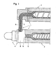
- the injection molding device 1 shown in the drawing for the production of multilayer molded articles made of thermoplastic material, which for example have a foamed core and an unfoamed outer skin, has two injection cylinders 2 and 3, which are designed, for example, as screw plasticizing cylinders.
- the two injection cylinders 2 and 3 according to FIG. 1 extend parallel to one another. It is of course also possible to arrange the injection cylinder 3 inclined relative to the injection cylinder 2 or to provide it in a position perpendicular to it.
- the spray head 4 is arranged at the front end thereof, plastic material 5 which can be plasticized directly from the injection cylinder 2 can be introduced into it, while plastic injection material 7 plasticized from the injection cylinder 3 can be introduced into it indirectly from the injection cylinder 3.
- the spray head 4 is designed and operates in such a way that it can be used to manufacture multi-layer molded parts which, for example, have a foamed core and an unfoamed outer skin.
- the plasticized plastic material 7 from the injection cylinder 3 is used as the core material and the plasticized plastic material 5 from the injection cylinder 2 is used as the skin material.
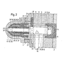
- the nozzle head 4 of the injection molding device 1 shown in the drawing has a main housing 8 which is connected to the end face of the injection cylinder 2, for example flanged to it, as can be seen in FIGS. 1 and 2.
- the main housing 8 has a central bore 9 and is provided on both ends with an annular groove 10 concentric with this central bore 9.
- annular groove 10 concentric with this central bore 9.
- connecting channels 12 are arranged, which are arranged according to FIG. 3 evenly distributed in the circumferential direction around the central bore 9 and each have a ring segment-shaped cross section, the arc radii of the ring segments with the arc radii of the two ring grooves 10 and 11 match.
- a material web 13 remains in the main housing 8 between the adjacent connecting channels 12, as can be clearly seen in FIG. 3.
- the rear end of the central bore 9 is closed by a cap-like guide body 14 for the plastic material 5, which tapers against the conveying direction of the injection cylinder 2, the guide body 14 being screwed, for example via an internal thread 15, onto the external thread 16 of a stepped neck part 17, which is the central bore 9 delimited against the annular groove 10.
- the main housing 8 is provided with a neck 18, in which the annular groove 11 is located on the one hand and which on the other hand contains a radial channel 19 at a distance behind this annular groove and within two diametrically opposed webs 13, as shown in FIG. 2 and 3 can be seen.
- an annular flange 20 is pushed onto the neck 18, into which a semicircular annular channel 21 is incorporated in such a way that it ends at the ends of the circumferential surface of the neck 18 in the two radial channels 19 of the main housing 8.
- the semicircular ring channel 21 in turn has a radial connection channel 22 for the feed channel 6 of the injection cylinder 3 in the region of its half length.
- a central nozzle body 26 is screwed into a stepped internal thread 24 of the neck 23 by means of a stepped external thread 25, the inner circumference of which connects to the central bore 9 of the main housing 8, while its outer circumference has the same diameter as the outer circumference of the neck 23.
- a nozzle needle 27 is guided axially displaceably by means of its rear longitudinal section 28. Your front length section 29 is stepped down to a smaller diameter and at the front with a cone shaped tip 30 provided.
- the rear, larger diameter section 28 of the nozzle needle 27 cooperates with the radial channels 19 of the main housing 8 within the central bore 9 as a valve slide.
- the nozzle needle 27 can be displaced by means of a radial actuating arm 32 which projects laterally out of the main housing 8 through a radial longitudinal slot and on which an adjusting rod 34 engages.
- the radial longitudinal slot 33 is arranged in such a way that it leads inside the main housing 8 through a material web 13 lying between two adjacent connecting channels 12, as can be seen from FIG. 3.
- the central nozzle body 26 is surrounded at a concentric distance by an annular nozzle body 35 which is flanged to the annular flange 20 and braced against the end face of the neck 18 of the main housing 8.
- the inside diameter of the ring nozzle body 35 at its rear end corresponds to the outside diameter of the ring groove 11 in the neck 18 of the main housing 8, so that between it, the neck 23 of the main housing 8 and the outer periphery of the central nozzle body 26, the annular nozzle chamber 36 is limited.
- central nozzle chamber 31 is initially reduced in the area of an aerodynamically shaped shoulder 37 by approximately half its length in its annular flow cross section and that it forms the central nozzle mouth 39 together with the tip 30 of the nozzle needle 27 via an arcuate end section 38, that is, when the nozzle needle 27 assumes the sliding position shown in broken lines in FIG. 2.
- the annular nozzle chamber 36 also has a reduced flow cross-section in the region of a flow-shaped shoulder 40 and is then led forward through the converging annular gap between the zebtral nozzle body 26 and the annular nozzle body 35 to the annular nozzle mouth 41, which is open when the nozzle needle 27 is in contact with it Tip 30 occupies the sliding position indicated by dashed lines in Fig. 2.
- Fig. 2 makes it clear that the central nozzle mouth 39 and the ring nozzle mouth 41 with a predetermined and unchangeable, axial distance 42 open in succession in the spray head 4 and the central nozzle mouth 39 is in the direction of flow in front of the ring nozzle mouth 41. It can also be seen that the central nozzle mouth 39 and the ring nozzle mouth 41 have the same mouth diameter and thus the front longitudinal section 29 of the nozzle needle 27 can be used both as a closing element for the ring nozzle mouth 41 and as a closing element for the central nozzle mouth 39.
- both the ring nozzle mouth 41 and the central nozzle mouth 39 are blocked, and the outlet opening 43 of the spray head 4 is closed.
- the outlet opening 43 of the spray head 4 is in the sliding position of the nozzle needle 27 drawn by dashed lines opened and at the same time the ring nozzle mouth 41 released. If the plasticized plastic material present in the ring nozzle chamber 36 is then pressurized by the injection cylinder 2, it can be pressed through the ring nozzle mouth 41 and the outlet opening 43 into the subsequent injection mold (not shown).
- the central nozzle mouth 39 is also opened and at the same time the central nozzle chamber 31 is brought into flow connection with the radial channels 19. If the injection cylinder 3 is then pressurized, the plasticized plastic material 7 is also brought through the outlet opening 43 into the injection mold (not shown) as a core material which is surrounded on all sides by the plasticized plastic material 5 as the skin material.
- the plasticized plastic material 7 serving as the core material can be a blowing agent-containing and thus foaming plastic, while the thermoplastic material 5 contains no blowing agent and thus gets into the injection mold without foaming.
- the embodiment of an injection molding device described above is designed so that the injection process first begins with the exit of the plasticized plastic material 5 from the ring nozzle mouth 41 and then additional plasticized plastic material is then fed from the central nozzle opening 39. At the end of the spraying process, the supply of the plastic material 7 from the central nozzle mouth 39 is interrupted again and then the supply of the plastic material from the ring nozzle mouth 41 is stopped.
- the structural design of the injection molding device 1 described above is advantageous in that all the components of the same can be designed as turned parts. Only on the main housing 8 and on the ring flange 20 additional drilling and milling work is required to a small extent.
- the radial connecting channels 19 from the injection cylinder 3 to the central nozzle chamber 31 are at a distance from the central nozzle mouth 39 which is equal to or slightly smaller than the length of the length section 28 of the nozzle needle 27 which is reduced to the smaller diameter. This ensures that the larger diameter longitudinal section 28 of the nozzle needle 27 forms the valve slide, via which the radial connecting channels 19 to the central nozzle chamber 31 are blocked by the front end 30 of the nozzle needle 27 until the central nozzle mouth 39 is released.
- the ring channel 21 has a smallest radius which is larger than the largest radius on the ring nozzle chamber 36 or on the ring groove 11. The ring channel 21 can then be simply milled into the back of the ring flange 20 on its inner circumference, while the radial connecting channels 19 can be made as simple bores in the main housing 8.
- the nozzle needle 27 can also be offset, i.e. have a smaller diameter in the area of the ring nozzle mouth 41 than in the area of the central nozzle mouth 39, in which case the two nozzles orifices must also have different diameters.
Landscapes
- Engineering & Computer Science (AREA)
- Manufacturing & Machinery (AREA)
- Mechanical Engineering (AREA)
- Injection Moulding Of Plastics Or The Like (AREA)
- Processing And Handling Of Plastics And Other Materials For Molding In General (AREA)
- Manufacture Of Porous Articles, And Recovery And Treatment Of Waste Products (AREA)
- Containers And Packaging Bodies Having A Special Means To Remove Contents (AREA)
- Extrusion Moulding Of Plastics Or The Like (AREA)
Priority Applications (1)
| Application Number | Priority Date | Filing Date | Title |
|---|---|---|---|
| AT81105063T ATE5385T1 (de) | 1980-07-05 | 1981-06-30 | Vorrichtung zum herstellen von mehrschichtformteilen aus thermoplastischen kunststoffen. |
Applications Claiming Priority (2)
| Application Number | Priority Date | Filing Date | Title |
|---|---|---|---|
| DE3025597 | 1980-07-05 | ||
| DE3025597A DE3025597C2 (de) | 1980-07-05 | 1980-07-05 | Spritzkopf zum Spritzgießen von Mehrschicht-Formteilen aus zwei unterschiedlichen, aus zwei getrennten Spritzzylindern einführbaren Kunststoffen |
Publications (2)
| Publication Number | Publication Date |
|---|---|
| EP0043543A1 true EP0043543A1 (fr) | 1982-01-13 |
| EP0043543B1 EP0043543B1 (fr) | 1983-11-23 |
Family
ID=6106535
Family Applications (1)
| Application Number | Title | Priority Date | Filing Date |
|---|---|---|---|
| EP81105063A Expired EP0043543B1 (fr) | 1980-07-05 | 1981-06-30 | Procédé de fabrication de pièces moulées constituées de plusieurs couches en matière thermoplastique |
Country Status (6)
| Country | Link |
|---|---|
| US (1) | US4376625A (fr) |
| EP (1) | EP0043543B1 (fr) |
| AT (1) | ATE5385T1 (fr) |
| AU (1) | AU543087B2 (fr) |
| BR (1) | BR8104261A (fr) |
| DE (2) | DE3025597C2 (fr) |
Cited By (5)
| Publication number | Priority date | Publication date | Assignee | Title |
|---|---|---|---|---|
| EP0569859A1 (fr) * | 1992-05-11 | 1993-11-18 | Jobst Ulrich Gellert | Appareil de moulage par co-injection ayant un mécanisme à entraînement axial et rotatif |
| EP0599009A1 (fr) * | 1992-11-24 | 1994-06-01 | Asahi Kasei Kogyo Kabushiki Kaisha | Moulage par l'injection d'un résine synthétique |
| NL1001417C2 (nl) * | 1995-10-13 | 1997-04-15 | Inter Tooling Services Bv | Inrichting voor het vervaardigen van holle kunststof voorwerpen. |
| US6183673B1 (en) * | 1998-04-24 | 2001-02-06 | Industrial Thermo Ploymers Limited | Method for forming extruded foam with surface coating |
| DE102013015800A1 (de) * | 2013-09-24 | 2015-03-26 | Wittmann Battenfeld Gmbh | Spritzgießmaschine |
Families Citing this family (36)
| Publication number | Priority date | Publication date | Assignee | Title |
|---|---|---|---|---|
| US5074771A (en) * | 1982-12-27 | 1991-12-24 | Amp Incorporated | Dual injection molding apparatus |
| US5523045A (en) | 1983-04-13 | 1996-06-04 | American National Can Company | Methods for injection molding and blow-molding multi-layer plastic articles |
| US4934915A (en) * | 1983-04-13 | 1990-06-19 | American National Can Company | Apparatus for injection molding multi-layer articles |
| US5037285A (en) | 1983-04-13 | 1991-08-06 | American National Can Company | Apparatus for injection molding and injection blow molding multi-layer articles |
| US4712990A (en) * | 1983-04-13 | 1987-12-15 | American Can Company | Apparatus for injection molding and injection blow molding multi-layer articles |
| US4895504A (en) * | 1983-04-13 | 1990-01-23 | American National Can Company | Apparatus for injection molding and injection blow molding multi-layer articles |
| US4931246A (en) * | 1983-04-13 | 1990-06-05 | American National Can Company | Method for injection molding multi-layer articles |
| US6129960A (en) | 1983-04-13 | 2000-10-10 | Pechiney Plastic Packaging, Inc. | Methods and apparatus for injection molding and injection blow molding multi-layer plastic and the articles made thereby |
| US4892699A (en) * | 1983-04-13 | 1990-01-09 | American National Can Company | Methods for injection molding and injection blow molding multi-layer articles |
| US4946365A (en) * | 1983-04-13 | 1990-08-07 | American National Can Company | Apparatus for injection molding and injection blow molding multi-layer articles |
| US4657496A (en) * | 1984-06-04 | 1987-04-14 | Gifu Husky Co., Ltd. | Hot-runner mold for injection molding |
| US4828780A (en) * | 1987-12-01 | 1989-05-09 | Killon Extruders, Inc. | Method for encapsulating extruding materials |
| US4905901A (en) * | 1988-08-30 | 1990-03-06 | Sajar Plastics, Inc. | Injection molding nozzle |
| AT402485B (de) * | 1989-08-22 | 1997-05-26 | Battenfeld Gmbh | Spritzkopf zum spritzgiessen von kunststoff nach dem injektionsverfahren |
| EP0581902A4 (fr) * | 1991-04-19 | 1994-03-23 | Surface Solutions Inc | Procede et appareil de pulverisation lineaire au magnetron. |
| US5407342A (en) * | 1993-09-13 | 1995-04-18 | Boucher; Paul Y. | Apparatus for manufacturing a composite product |
| DE4340990C2 (de) * | 1993-11-05 | 1996-09-19 | Battenfeld Gmbh | Verfahren und Vorrichtung zum Spritzgießen von mehrschichtigen Gegenständen |
| US5501594A (en) * | 1994-02-16 | 1996-03-26 | Eastman Kodak Company | Apparatus for forming a thermoplastic body |
| US5650178A (en) * | 1994-11-23 | 1997-07-22 | Bemis Manufacturing Company | Co-injection manifold for injection molding |
| US5798162A (en) * | 1996-09-04 | 1998-08-25 | The Dow Chemical Company | Composites of crystalline polymers |
| JP2002513690A (ja) | 1998-05-01 | 2002-05-14 | エフイ−アイ エンタープライジズ,リミティド | 制御放出デバイスの射出成形製造方法 |
| US6524089B1 (en) * | 1998-05-29 | 2003-02-25 | Pechiney Emballage Flexible Europe | Multilayer injection nozzle assembly |
| US6196822B1 (en) | 1998-12-18 | 2001-03-06 | Incoe Corporation | Conversion manifold for multiple injection unit injection molding machine |
| US6440350B1 (en) | 1999-03-18 | 2002-08-27 | Mold-Masters Limited | Apparatus and method for multi-layer injection molding |
| US6655945B1 (en) | 1999-03-18 | 2003-12-02 | Mold Masters Limited | Apparatus and method for multi-layer injection molding |
| US6398537B2 (en) | 1999-04-02 | 2002-06-04 | Mold-Masters Limited | Shuttle system for an apparatus for injection molding |
| US6196826B1 (en) | 1999-05-28 | 2001-03-06 | Mold-Masters Limited | Seepage system for an injection molding apparatus |
| WO2001064419A1 (fr) * | 2000-02-29 | 2001-09-07 | Bemis Manufacturing Company | Appareil a co-injection pour moulage par injection |
| US6964748B2 (en) * | 2000-11-30 | 2005-11-15 | Bemis Manufacturing Company | Co-injection methods using endothermic-blowing agents and products made therefrom |
| JP2003181873A (ja) * | 2001-12-21 | 2003-07-02 | Toshiba Mach Co Ltd | 射出成形機の樹脂替え方法及びサンドイッチ成形品 |
| US7390184B2 (en) * | 2005-11-09 | 2008-06-24 | Centoco Plastics Limited | Dual injection manifold |
| US7458795B2 (en) * | 2006-02-24 | 2008-12-02 | Incoe Corporation | Co-injection nozzle assembly |
| MX2009000677A (es) | 2006-07-19 | 2009-02-13 | Eaton Corp | Conjunto de acoplamiento y reten para uso con el mismo. |
| US20100283308A1 (en) * | 2009-05-11 | 2010-11-11 | Knoll, Inc. | Co-injection molded chair |
| WO2014070875A1 (fr) | 2012-11-01 | 2014-05-08 | Ticona Llc | Objet multicouche moulé par co-injection |
| KR20170029860A (ko) * | 2015-09-08 | 2017-03-16 | 삼성전자주식회사 | 휴대폰 케이스 및 휴대폰 케이스 사출 금형 |
Citations (8)
| Publication number | Priority date | Publication date | Assignee | Title |
|---|---|---|---|---|
| DE2342789A1 (de) * | 1973-08-24 | 1975-03-13 | Schloemann Siemag Ag | Vorrichtung zur diskontinuierlichen herstellung von mehrschicht-formkoerpern |
| DE2346135A1 (de) * | 1973-09-13 | 1975-04-03 | Schloemann Siemag Ag | Verfahren und vorrichtung zum diskontinuierlichen herstellen von mehrschichtformteilen aus thermoplastischem kunststoff |
| DE2259818B2 (de) * | 1972-12-07 | 1975-06-12 | Schloemann-Siemag Ag, 4000 Duesseldorf | SpritzgieBvorrichtung zum Herstellen eines Formkörpers mit einem Kern aus geschäumtem und einer Außenhaut aus ungeschäumten thermoplastischem Kunststoff |
| US3921856A (en) * | 1972-09-27 | 1975-11-25 | Erhard Langecker | Injection molding nozzle |
| DE2449758A1 (de) * | 1974-10-19 | 1976-04-29 | Schloemann Siemag Ag | Verfahren und vorrichtung zur herstellung von kunststoff-formteilen mit einem geschaeumten kern und einer ungeschaeumten aussenhaut |
| DE2800482A1 (de) * | 1977-01-05 | 1978-07-06 | Asahi Dow Ltd | Verfahren zur herstellung von formkoerpern |
| US4117955A (en) * | 1977-04-13 | 1978-10-03 | Beloit Corporation | Multi-port valved nozzle for co-injection molding |
| DE2247995B2 (de) * | 1972-09-27 | 1980-02-07 | Erhard 5882 Meinerzhagen Langecker | Verfahren und Vorrichtung zum Spritzgießen von Kunststofformkörpern, die aus einer Füllschicht aus einem thermoplastischen Kunststoff und aus einer dieser einschließenden Deckschicht aus einem anderen thermoplastischen Kunststoff bestehen |
Family Cites Families (2)
| Publication number | Priority date | Publication date | Assignee | Title |
|---|---|---|---|---|
| DE2342794C3 (de) | 1973-08-24 | 1981-09-17 | Schloemann-Siemag AG, 4000 Düsseldorf | Verfahren und Vorrichtung zum diskontinuierlichen Herstellen von Mehrschicht- Formteilen aus thermoplastischem Kunststoff |
| US4078875A (en) * | 1974-10-19 | 1978-03-14 | Schloemann-Siemag Akt. | Injection molding |
-
1980
- 1980-07-05 DE DE3025597A patent/DE3025597C2/de not_active Expired
-
1981
- 1981-06-29 US US06/278,429 patent/US4376625A/en not_active Expired - Fee Related
- 1981-06-30 EP EP81105063A patent/EP0043543B1/fr not_active Expired
- 1981-06-30 DE DE8181105063T patent/DE3161495D1/de not_active Expired
- 1981-06-30 AT AT81105063T patent/ATE5385T1/de active
- 1981-07-02 AU AU72512/81A patent/AU543087B2/en not_active Ceased
- 1981-07-03 BR BR8104261A patent/BR8104261A/pt unknown
Patent Citations (8)
| Publication number | Priority date | Publication date | Assignee | Title |
|---|---|---|---|---|
| US3921856A (en) * | 1972-09-27 | 1975-11-25 | Erhard Langecker | Injection molding nozzle |
| DE2247995B2 (de) * | 1972-09-27 | 1980-02-07 | Erhard 5882 Meinerzhagen Langecker | Verfahren und Vorrichtung zum Spritzgießen von Kunststofformkörpern, die aus einer Füllschicht aus einem thermoplastischen Kunststoff und aus einer dieser einschließenden Deckschicht aus einem anderen thermoplastischen Kunststoff bestehen |
| DE2259818B2 (de) * | 1972-12-07 | 1975-06-12 | Schloemann-Siemag Ag, 4000 Duesseldorf | SpritzgieBvorrichtung zum Herstellen eines Formkörpers mit einem Kern aus geschäumtem und einer Außenhaut aus ungeschäumten thermoplastischem Kunststoff |
| DE2342789A1 (de) * | 1973-08-24 | 1975-03-13 | Schloemann Siemag Ag | Vorrichtung zur diskontinuierlichen herstellung von mehrschicht-formkoerpern |
| DE2346135A1 (de) * | 1973-09-13 | 1975-04-03 | Schloemann Siemag Ag | Verfahren und vorrichtung zum diskontinuierlichen herstellen von mehrschichtformteilen aus thermoplastischem kunststoff |
| DE2449758A1 (de) * | 1974-10-19 | 1976-04-29 | Schloemann Siemag Ag | Verfahren und vorrichtung zur herstellung von kunststoff-formteilen mit einem geschaeumten kern und einer ungeschaeumten aussenhaut |
| DE2800482A1 (de) * | 1977-01-05 | 1978-07-06 | Asahi Dow Ltd | Verfahren zur herstellung von formkoerpern |
| US4117955A (en) * | 1977-04-13 | 1978-10-03 | Beloit Corporation | Multi-port valved nozzle for co-injection molding |
Cited By (7)
| Publication number | Priority date | Publication date | Assignee | Title |
|---|---|---|---|---|
| EP0569859A1 (fr) * | 1992-05-11 | 1993-11-18 | Jobst Ulrich Gellert | Appareil de moulage par co-injection ayant un mécanisme à entraînement axial et rotatif |
| EP0599009A1 (fr) * | 1992-11-24 | 1994-06-01 | Asahi Kasei Kogyo Kabushiki Kaisha | Moulage par l'injection d'un résine synthétique |
| US5424112A (en) * | 1992-11-24 | 1995-06-13 | Asahi Kasei Kogyo Kabushiki Kaisha | Injection molding of a synthetic resin |
| NL1001417C2 (nl) * | 1995-10-13 | 1997-04-15 | Inter Tooling Services Bv | Inrichting voor het vervaardigen van holle kunststof voorwerpen. |
| US5897822A (en) * | 1995-10-13 | 1999-04-27 | Inter Tooling Services B.V. | Method of manufacturing hollow plastic articles |
| US6183673B1 (en) * | 1998-04-24 | 2001-02-06 | Industrial Thermo Ploymers Limited | Method for forming extruded foam with surface coating |
| DE102013015800A1 (de) * | 2013-09-24 | 2015-03-26 | Wittmann Battenfeld Gmbh | Spritzgießmaschine |
Also Published As
| Publication number | Publication date |
|---|---|
| US4376625A (en) | 1983-03-15 |
| DE3025597A1 (de) | 1982-01-21 |
| DE3025597C2 (de) | 1984-06-14 |
| AU7251281A (en) | 1982-01-14 |
| BR8104261A (pt) | 1982-03-23 |
| DE3161495D1 (en) | 1983-12-29 |
| EP0043543B1 (fr) | 1983-11-23 |
| AU543087B2 (en) | 1985-03-28 |
| ATE5385T1 (de) | 1983-12-15 |
Similar Documents
| Publication | Publication Date | Title |
|---|---|---|
| EP0043543B1 (fr) | Procédé de fabrication de pièces moulées constituées de plusieurs couches en matière thermoplastique | |
| AT395555B (de) | Vorrichtung zum spritzgiessen von hohlraeume enthaltenden gegenstaenden aus kunststoff | |
| EP0310914B1 (fr) | Procédé pour mouler par injection des pièces en matière synthétique thermoplastique ainsi que dispositif pour la réalisation du procédé | |
| EP0261350B1 (fr) | Dispositif pour fabriquer des pièces moulées en matière plastique | |
| EP0137250B1 (fr) | Buse multiple pour réunir au moins deux réactants fluides formant de la matière plastique, en particulier de la matière plastique alvéolaire, en vue de déclencher la réaction par mélange et procédé pour le fonctionnement de ladite buse multiple | |
| EP0360189B1 (fr) | Buse d'injection pour une machine à mouler par injection | |
| EP0363948B1 (fr) | Buse pour machines de moulage par injection | |
| DE2519932C2 (de) | Verschlußdüse zum Einspritzen von geschmolzenem Kunststoff | |
| DE4103318C2 (de) | Spritzkopf | |
| EP0262470B1 (fr) | Tête d'injection pour fabriquer des objets moulés à plusieurs couches en matière thermoplastique | |
| DE69228683T2 (de) | Düse für gasunterstütztes spritzgiessen | |
| EP0099045B1 (fr) | Méthode et tête de mélange pour la fabrication d'un mélange ayant au moins deux composants réactifs pouvant couler et formant une matière plastique | |
| DE60006654T2 (de) | Vorrichtung zum mehrschichtspritzgiessen | |
| EP0467129B1 (fr) | Buse pour machines à mouler par injection | |
| DE1261657B (de) | Spritzkopf zum Herstellen von schlauchfoermigen Straengen | |
| EP1107855B1 (fr) | Procede et dispositif de moulage par injection d'une matiere plastique | |
| DE3247000C2 (fr) | ||
| DE69005254T2 (de) | Injektor für Druckgas in eine Form zum Herstellen eines Kunststoffteils, Form und Formverfahren unter Verwendung eines solchen Injektors und erhaltenes Kunststoffteil. | |
| EP0657268B1 (fr) | Procédé et dispositif de moulage par injection d'articles multicouches | |
| DE3504816A1 (de) | Vorrichtung zum gleichzeitigen anspritzen mehrerer formteile in einem spritzwerkzeug | |
| AT391294B (de) | Spritzgussduese | |
| EP0234522B1 (fr) | Tête de buse pour expulser facultativement plusieurs composants différents de matière plastique d'une pièce de buse centrale | |
| DE19722612C1 (de) | Vorrichtung zum Spritzgießen eines Werkstückes aus mindestens zwei unterschiedlichen Materialkomponenten | |
| DE4211458A1 (de) | Einrichtung zum Herstellen eines fließfähigen Reaktionsgemisches aus mindestens zwei fließfähigen, miteinander zu Massivstoff oder Schaumstoff reagierenden Reaktionskomponenten | |
| DE2416780C3 (de) | Angußvorrichtung zum Mischen von mindestens zwei flüssigen Komponenten eines insbesondere zellbildenden Kunststoffes |
Legal Events
| Date | Code | Title | Description |
|---|---|---|---|
| PUAI | Public reference made under article 153(3) epc to a published international application that has entered the european phase |
Free format text: ORIGINAL CODE: 0009012 |
|
| 17P | Request for examination filed |
Effective date: 19810630 |
|
| AK | Designated contracting states |
Designated state(s): AT DE FR GB IT |
|
| ITF | It: translation for a ep patent filed | ||
| GRAA | (expected) grant |
Free format text: ORIGINAL CODE: 0009210 |
|
| AK | Designated contracting states |
Designated state(s): AT DE FR GB IT |
|
| REF | Corresponds to: |
Ref document number: 5385 Country of ref document: AT Date of ref document: 19831215 Kind code of ref document: T |
|
| REF | Corresponds to: |
Ref document number: 3161495 Country of ref document: DE Date of ref document: 19831229 |
|
| ET | Fr: translation filed | ||
| PGFP | Annual fee paid to national office [announced via postgrant information from national office to epo] |
Ref country code: FR Payment date: 19840326 Year of fee payment: 4 |
|
| PLBE | No opposition filed within time limit |
Free format text: ORIGINAL CODE: 0009261 |
|
| STAA | Information on the status of an ep patent application or granted ep patent |
Free format text: STATUS: NO OPPOSITION FILED WITHIN TIME LIMIT |
|
| 26N | No opposition filed | ||
| PGFP | Annual fee paid to national office [announced via postgrant information from national office to epo] |
Ref country code: AT Payment date: 19860605 Year of fee payment: 6 |
|
| GBPC | Gb: european patent ceased through non-payment of renewal fee | ||
| PG25 | Lapsed in a contracting state [announced via postgrant information from national office to epo] |
Ref country code: GB Effective date: 19881118 |
|
| PG25 | Lapsed in a contracting state [announced via postgrant information from national office to epo] |
Ref country code: AT Effective date: 19890630 |
|
| PGFP | Annual fee paid to national office [announced via postgrant information from national office to epo] |
Ref country code: DE Payment date: 19900213 Year of fee payment: 9 |
|
| PG25 | Lapsed in a contracting state [announced via postgrant information from national office to epo] |
Ref country code: FR Free format text: LAPSE BECAUSE OF NON-PAYMENT OF DUE FEES Effective date: 19900228 |
|
| REG | Reference to a national code |
Ref country code: FR Ref legal event code: ST |
|
| PG25 | Lapsed in a contracting state [announced via postgrant information from national office to epo] |
Ref country code: DE Effective date: 19910301 |