EP0043574A1 - Plaque de refroidissement - Google Patents
Plaque de refroidissement Download PDFInfo
- Publication number
- EP0043574A1 EP0043574A1 EP81105196A EP81105196A EP0043574A1 EP 0043574 A1 EP0043574 A1 EP 0043574A1 EP 81105196 A EP81105196 A EP 81105196A EP 81105196 A EP81105196 A EP 81105196A EP 0043574 A1 EP0043574 A1 EP 0043574A1
- Authority
- EP
- European Patent Office
- Prior art keywords
- cooling water
- tail flange
- water channel
- cooling
- horseshoe
- Prior art date
- Legal status (The legal status is an assumption and is not a legal conclusion. Google has not performed a legal analysis and makes no representation as to the accuracy of the status listed.)
- Ceased
Links
- 238000001816 cooling Methods 0.000 title claims abstract description 57
- 239000000498 cooling water Substances 0.000 claims abstract description 100
- 238000003780 insertion Methods 0.000 claims abstract description 8
- 230000037431 insertion Effects 0.000 claims abstract description 8
- 238000005192 partition Methods 0.000 claims description 54
- XLYOFNOQVPJJNP-UHFFFAOYSA-N water Substances O XLYOFNOQVPJJNP-UHFFFAOYSA-N 0.000 abstract description 14
- RYGMFSIKBFXOCR-UHFFFAOYSA-N Copper Chemical compound [Cu] RYGMFSIKBFXOCR-UHFFFAOYSA-N 0.000 description 5
- 229910052802 copper Inorganic materials 0.000 description 5
- 239000010949 copper Substances 0.000 description 5
- 238000010276 construction Methods 0.000 description 3
- 230000007812 deficiency Effects 0.000 description 2
- 238000004519 manufacturing process Methods 0.000 description 2
- 210000001015 abdomen Anatomy 0.000 description 1
- 230000001133 acceleration Effects 0.000 description 1
- 230000004075 alteration Effects 0.000 description 1
- 238000009835 boiling Methods 0.000 description 1
- 238000005266 casting Methods 0.000 description 1
- 238000004891 communication Methods 0.000 description 1
- 238000005336 cracking Methods 0.000 description 1
- 238000009434 installation Methods 0.000 description 1
- 238000002844 melting Methods 0.000 description 1
- 230000008018 melting Effects 0.000 description 1
- 239000002184 metal Substances 0.000 description 1
- 229910052751 metal Inorganic materials 0.000 description 1
- 239000011819 refractory material Substances 0.000 description 1
- 239000004576 sand Substances 0.000 description 1
Images

Classifications
-
- C—CHEMISTRY; METALLURGY
- C21—METALLURGY OF IRON
- C21B—MANUFACTURE OF IRON OR STEEL
- C21B7/00—Blast furnaces
- C21B7/10—Cooling; Devices therefor
-
- F—MECHANICAL ENGINEERING; LIGHTING; HEATING; WEAPONS; BLASTING
- F27—FURNACES; KILNS; OVENS; RETORTS
- F27D—DETAILS OR ACCESSORIES OF FURNACES, KILNS, OVENS OR RETORTS, IN SO FAR AS THEY ARE OF KINDS OCCURRING IN MORE THAN ONE KIND OF FURNACE
- F27D1/00—Casings; Linings; Walls; Roofs
- F27D1/12—Casings; Linings; Walls; Roofs incorporating cooling arrangements
-
- F—MECHANICAL ENGINEERING; LIGHTING; HEATING; WEAPONS; BLASTING
- F28—HEAT EXCHANGE IN GENERAL
- F28F—DETAILS OF HEAT-EXCHANGE AND HEAT-TRANSFER APPARATUS, OF GENERAL APPLICATION
- F28F13/00—Arrangements for modifying heat-transfer, e.g. increasing, decreasing
- F28F13/06—Arrangements for modifying heat-transfer, e.g. increasing, decreasing by affecting the pattern of flow of the heat-exchange media
-
- F—MECHANICAL ENGINEERING; LIGHTING; HEATING; WEAPONS; BLASTING
- F28—HEAT EXCHANGE IN GENERAL
- F28F—DETAILS OF HEAT-EXCHANGE AND HEAT-TRANSFER APPARATUS, OF GENERAL APPLICATION
- F28F19/00—Preventing the formation of deposits or corrosion, e.g. by using filters or scrapers
-
- F—MECHANICAL ENGINEERING; LIGHTING; HEATING; WEAPONS; BLASTING
- F28—HEAT EXCHANGE IN GENERAL
- F28F—DETAILS OF HEAT-EXCHANGE AND HEAT-TRANSFER APPARATUS, OF GENERAL APPLICATION
- F28F3/00—Plate-like or laminated elements; Assemblies of plate-like or laminated elements
- F28F3/12—Elements constructed in the shape of a hollow panel, e.g. with channels
-
- F—MECHANICAL ENGINEERING; LIGHTING; HEATING; WEAPONS; BLASTING
- F27—FURNACES; KILNS; OVENS; RETORTS
- F27D—DETAILS OR ACCESSORIES OF FURNACES, KILNS, OVENS OR RETORTS, IN SO FAR AS THEY ARE OF KINDS OCCURRING IN MORE THAN ONE KIND OF FURNACE
- F27D9/00—Cooling of furnaces or of charges therein
- F27D2009/0002—Cooling of furnaces
- F27D2009/004—Cooling of furnaces the cooling medium passing a waterbox
- F27D2009/0043—Insert type waterbox, e.g. cylindrical or flat type
Definitions
- the present invention relates to metallurgical apparatus and more particularly to cooling plates for insertion into the refractory lining of a blast furnace or the like.
- Cooling systems are provided for the furnace walls of shaft furnaces as e.g. blast furnaces to effectively cool the walls subjected to high temperature conditions.
- the cooling systems comprise a plurality of cooling plates inserted in a pattern developed to adequately cool the furnace walls so that failure or breakout is prevented.
- the cooling plates with circulating water are used in the bosh, belly and stack sections of a blast furnace to cool the refractory lining in order to stabilize and extend the life of refractories.
- the plates are generally inserted horizontally and imbedded in the refractory lining at desired spacing both in circumferential and vertical directions.
- the cooling plates are usually made of copper castings with essentially pure copper for high thermal conductivity.
- the cooling plates are subject to failure by burnout or cracking due to two main factors.
- One factor is insufficient water flow, resulting in insufficient heat transfer.
- the other and more important factor is the existence of stagnant zones inside the cooling plates; such as dead pockets, eddies or vortices.
- the stagnation of water causes film boiling on the surface of the copper plate, leading to melting and burnout.
- the failures not only necessitate purchase of a large quantity of expensive replacement plates, but also cause the shutdown of the furnace and consequent loss of production from that unit.
- the present invention accomplishes these objects by providing a cooling plate having a plurality of cooling water channels for the circulation of cooling water therethrough.
- the flow of the cooling water through the cooling water channels is directed from a tail flange around a nose section and back to the tail flange.
- Means which include a horseshoe baffle plate to divide the flow of water are provided to direct the cooling water smoothly around the nose section.
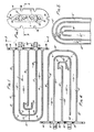
- a cooling plate 10 having a generally flat spade-like configuration which is cast in copper and defines a closed interior chamber 20 for the passage of cooling water therethrough.
- Top surface 11 and bottom surface 12 are connected in spaced relation by sidewall 13 which has an inner side 14.
- Sidewall 13 starts at tail flange 16, extends around nose section 15 in a loop and returns to tail flange 16 to form closed chamber 20 for the passage of cooling water.
- a first partition wall 17 is spaced from the inner side 14 of sidewall 13 starting at tail flange 16 extending around the nose section 15 and terminating at the end flange 16 to form a first cooling water channel 21 for the passage of cooling water.
- a second partition wall 18 inside first partition wall 17 extends outwardly from the tail flange 16 toward the nose section 15 having a terminus 19 spaced from the nose section of first partition wall 17 and forming a second cooling water channel 22.
- Located between the terminus 19 of partition wall 18 and nose section or loop 23 of partition wall 17 is a horseshoe-shaped baffle 24 with the open end of the horseshoe extending toward the tail flange 16.
- the horseshoe-shaped baffle 24 divides the flow of cooling water in the second cooling water channel 22 around the nose section or loop 23 to increase the velocity of flow of the cooling water and concurrently avoids stagnant zones in the loop area.
- Large radii "a”, “b”, “c” and “d” are provided at the loop area to assure the smooth flow of cooling water around the loops to facilitate the flow of cooling water through the water channels while avoiding stagnant zones.
- Cooling plate 10 is provided with four openings in the _tail flange 16 for water inlet/outlet connections.
- the inlet/outlet openings are also used as core sand removing holes.
- Lugs 35 are provided on tail flange 16 for handling the cooling plates for installation and removal.
- Bolt slots 36 are provided in the tail flange 16 for bolting the cooling plates 10 to the metal shell of the furnace.
- FIG. 1 The embodiment of the invention shown in FIG. 1 is a double chamber cooling plate wherein cooling water is injected at first and second cooling water inlets 31 and 32 into cooling water channels 21 and 22 respectively and discharged through first and second outlets 33 and 34 respectively.
- First cooling water inlet 31 and first cooling water outlet 33 are aligned with first cooling water channel 21.
- Second cooling water inlet 32 and second cooling water outlet 34 are aligned with cooling water channel 22.
- the cooling plate is a single chamber cooling plate, i.e. the cooling water is introduced at cooling water inlet or first opening 31' aligned with first cooling water channel 21', follows a circuitous flow through cooling water channels 21' and 22' to cooling water outlet or second opening 34' aligned with second cooling water channel 22', the water passing through the entire interior chamber before being discharged at opening 34'. Plugs are placed in openings 32' and 33' to close the openings in this single chamber cooling plate.
- the alternate embodiment shown in FIG. 4 is similar in construction to the embodiment of FIG. 1 except for details to be described.
- the cooling plate 10' comprises a top surface (not shown) similar in all respects to top surface 11 connected to bottom surface 12' by sidewall 13' having an inner side 14', first partition wall 17' and second partition wall 18'.
- a first cooling water channel 21' is defined by the space between inner side 14' and first partition wall 17'.
- the second cooling water channel 22' is defined by the space between first partition 17' and second partition wall 18' and one end of first water channel 21' is in communication with one end of second water channel 22' at opening 40'. Opening 40' is created by the termination of first partition wall 17' spaced from end flange 16'.
- a horseshoe baffle 24' is located similarly to divide the flow of cooling water in the second cooling water channel 22' to increase the velocity of flow thereof and to avoid stagnant zones.
- FIG. 5 shows an alternate embodiment of the invention wherein the nose section 15'' comprises semicircular curves for the loop portions of sidewall 13", partition 23" and horseshoe 24".
- the alternate embodiment shown in FIG. 6 is similar in construction to the embodiment of FIG. 1 except for details to be described.
- the cooling plate 60 comprises a top surface (not shown) similar in all respects to top surface 11 connected to bottom surface 62 by sidewall 63 having an inner side 64, first partition wall 67 and second partition wall 68.
- a first cooling water channel 71 is defined by the space between inner side 64 and first partition wall 67.
- the second cooling water channel 72 is defined by the space between first partition 67 and second partition wall 68.
- a horseshoe baffle 74 is located between sidewall 63 and first partition wall 67 to divide the flow of cooling water in the first cooling water channel 71 to increase the velocity of flow thereof and to avoid stagnant zones.
- FIG. 1 shows a cooling plate for insertion in the lining of a blast furnace cast from essentially pure copper, tested with 125# steam pressure.
- the outside dimensions of the cooling plate include 40 inch length overall, 14 inch width and 4-3/4 inches depth.
- Cooling water channel 21 measures approximately 1-1/4 inches wide by 3-5/8 inches depth, sidewall 13 being rounded as is clear from FIG. 3.
- the partition walls 17 and 18 are 7/16 inch thick and cooling water channel 22 measures 3-1/2 inches wide by 3-5/8 inches deep.
- a horseshoe-shaped baffle 24 is inserted in second cooling water channel 22 to divide the stream of cooling water to overcome stagnant zones by virtue of the resulting configuration and the improved water velocity.
- the baffle 24 is 7/16 inch thick and has an opening of 3-1/2 inches.
- the legs of the horseshoe extend along the partition wall 18 for about 2 inches from the terminus 19.
- the water flow is generally maintained at 35 gpm.
- the cross sectional area of the cooling water channel 21 at location A is 3.08 in 2 and the velocity is 3.65 ft/sec.
- At location B in cooling water channel 22 having horseshoe-shaped baffle 24 therein the area is 4.33 in 2 and the velocity of flow of the cooling water is 2.59 ft./sec.
- the invention described hereinabove provides users of water cooled furnace cooling plates with a new and improved design of cooling plates to overcome stagnant zones in the water chamber such as dead pockets, eddies and/or vortices. These stagnant zones are responsible for burnouts in existing plates.
- the improved water velocity resulting from the design of the invention improves heat transfer and extends service life.
- the design of this invention maintains low pressure drop within the cooling plates by streamlining the water passageways, avoiding sharp curves and bends and providing gradual acceleration and deceleration of water flow both in the straight and curved sections.
Landscapes
- Engineering & Computer Science (AREA)
- Mechanical Engineering (AREA)
- General Engineering & Computer Science (AREA)
- Physics & Mathematics (AREA)
- Thermal Sciences (AREA)
- Chemical & Material Sciences (AREA)
- Manufacturing & Machinery (AREA)
- Materials Engineering (AREA)
- Metallurgy (AREA)
- Organic Chemistry (AREA)
- Blast Furnaces (AREA)
- Furnace Housings, Linings, Walls, And Ceilings (AREA)
Applications Claiming Priority (2)
| Application Number | Priority Date | Filing Date | Title |
|---|---|---|---|
| US16671180A | 1980-07-07 | 1980-07-07 | |
| US166711 | 1980-07-07 |
Publications (1)
| Publication Number | Publication Date |
|---|---|
| EP0043574A1 true EP0043574A1 (fr) | 1982-01-13 |
Family
ID=22604403
Family Applications (1)
| Application Number | Title | Priority Date | Filing Date |
|---|---|---|---|
| EP81105196A Ceased EP0043574A1 (fr) | 1980-07-07 | 1981-07-04 | Plaque de refroidissement |
Country Status (5)
| Country | Link |
|---|---|
| EP (1) | EP0043574A1 (fr) |
| JP (1) | JPS5773387A (fr) |
| AU (1) | AU7260681A (fr) |
| BR (1) | BR8104286A (fr) |
| ZA (1) | ZA814492B (fr) |
Cited By (3)
| Publication number | Priority date | Publication date | Assignee | Title |
|---|---|---|---|---|
| GB2176883A (en) * | 1984-04-19 | 1987-01-07 | Hylsa Sa | Cooling panel for furnace |
| CN102655755A (zh) * | 2009-11-18 | 2012-09-05 | 伊利诺斯工具制品有限公司 | 面团搅拌机及具有冷却套管流道的搅拌钵 |
| CN103642959A (zh) * | 2013-11-18 | 2014-03-19 | 苏州边枫电子科技有限公司 | 组合式冷却板 |
Families Citing this family (2)
| Publication number | Priority date | Publication date | Assignee | Title |
|---|---|---|---|---|
| JPS59219405A (ja) * | 1983-05-26 | 1984-12-10 | Nippon Kokan Kk <Nkk> | 冷却函 |
| EP3604560A1 (fr) * | 2018-08-01 | 2020-02-05 | Paul Wurth S.A. | Boîte de refroidissement pour four à cuve |
Citations (8)
| Publication number | Priority date | Publication date | Assignee | Title |
|---|---|---|---|---|
| US1827231A (en) * | 1929-12-04 | 1931-10-13 | William A Haven | Heat exchanging device |
| US2891783A (en) * | 1957-04-11 | 1959-06-23 | Bethlehem Steel Corp | Blast furnace tuyere |
| US3241528A (en) * | 1963-06-13 | 1966-03-22 | American Brake Shoe Co | Blast furnace cooling plates |
| US3598382A (en) * | 1969-07-09 | 1971-08-10 | Nat Steel Corp | Furnace wall cooling |
| FR2115771A5 (en) * | 1970-11-25 | 1972-07-07 | Dupret Emile Anc Ets | Cooling box, esp for blast furnaces |
| US4140302A (en) * | 1978-02-27 | 1979-02-20 | Lynch Roland H | Jet impingement cooling device |
| FR2430584A1 (fr) * | 1978-07-05 | 1980-02-01 | Solmer | Boite de refroidiss |
| US4210101A (en) * | 1977-05-25 | 1980-07-01 | Francois Touze | Heat exchange devices for cooling the wall and refractory of a blast furnace |
-
1981
- 1981-07-02 ZA ZA814492A patent/ZA814492B/xx unknown
- 1981-07-04 EP EP81105196A patent/EP0043574A1/fr not_active Ceased
- 1981-07-06 BR BR8104286A patent/BR8104286A/pt unknown
- 1981-07-06 AU AU72606/81A patent/AU7260681A/en not_active Abandoned
- 1981-07-07 JP JP56106191A patent/JPS5773387A/ja active Pending
Patent Citations (8)
| Publication number | Priority date | Publication date | Assignee | Title |
|---|---|---|---|---|
| US1827231A (en) * | 1929-12-04 | 1931-10-13 | William A Haven | Heat exchanging device |
| US2891783A (en) * | 1957-04-11 | 1959-06-23 | Bethlehem Steel Corp | Blast furnace tuyere |
| US3241528A (en) * | 1963-06-13 | 1966-03-22 | American Brake Shoe Co | Blast furnace cooling plates |
| US3598382A (en) * | 1969-07-09 | 1971-08-10 | Nat Steel Corp | Furnace wall cooling |
| FR2115771A5 (en) * | 1970-11-25 | 1972-07-07 | Dupret Emile Anc Ets | Cooling box, esp for blast furnaces |
| US4210101A (en) * | 1977-05-25 | 1980-07-01 | Francois Touze | Heat exchange devices for cooling the wall and refractory of a blast furnace |
| US4140302A (en) * | 1978-02-27 | 1979-02-20 | Lynch Roland H | Jet impingement cooling device |
| FR2430584A1 (fr) * | 1978-07-05 | 1980-02-01 | Solmer | Boite de refroidiss |
Cited By (3)
| Publication number | Priority date | Publication date | Assignee | Title |
|---|---|---|---|---|
| GB2176883A (en) * | 1984-04-19 | 1987-01-07 | Hylsa Sa | Cooling panel for furnace |
| CN102655755A (zh) * | 2009-11-18 | 2012-09-05 | 伊利诺斯工具制品有限公司 | 面团搅拌机及具有冷却套管流道的搅拌钵 |
| CN103642959A (zh) * | 2013-11-18 | 2014-03-19 | 苏州边枫电子科技有限公司 | 组合式冷却板 |
Also Published As
| Publication number | Publication date |
|---|---|
| BR8104286A (pt) | 1982-03-23 |
| ZA814492B (en) | 1982-07-28 |
| AU7260681A (en) | 1982-01-14 |
| JPS5773387A (en) | 1982-05-08 |
Similar Documents
| Publication | Publication Date | Title |
|---|---|---|
| US4637034A (en) | Cooling panel for electric arc furnace | |
| GB1558446A (en) | Cooling element for the walls of shaft furnaces particularly blast furnaces | |
| EP0043574A1 (fr) | Plaque de refroidissement | |
| US3638929A (en) | Discovery in apparatus for cooling a wall surface | |
| US4487400A (en) | Cooling plate | |
| US4561639A (en) | Cooling plate for metallurgical furnaces | |
| CA2591584A1 (fr) | Systemes et procedes de refroidissement de hauts fourneaux | |
| US4029053A (en) | Cooling box for metallurgical furnace | |
| JPS63176993A (ja) | 特に合成ガスとボイラー給水の間の熱交換のための装置 | |
| US4129172A (en) | Mold for electroslag remelting process | |
| US3705713A (en) | Bottom cooling device for shaft furnaces | |
| US4572269A (en) | Method of manufacturing cooling plates for use in metallurgical furnaces and a cooling plate | |
| JPH0141917B2 (fr) | ||
| US4669708A (en) | Cooling plates for blast-furnaces | |
| SU1036745A1 (ru) | Дутьева фурма доменной печи | |
| US4278241A (en) | Top cone cooling system for basic oxygen furnace | |
| US4281963A (en) | Apparatus for the conveyance and/or treatment of hot gases | |
| US3661372A (en) | Water-cooled panel | |
| US4245572A (en) | Furnace cooling system | |
| RU2067999C1 (ru) | Фурма доменной печи | |
| CA1125505A (fr) | Tuyere faconnee d'insuflaton | |
| US20040256772A1 (en) | Cooling plate comprising a reinforcement element | |
| KR100439642B1 (ko) | 액체 강철을 진공 처리하기 위한 수냉 프로세스 베젤(vessel) | |
| US5409197A (en) | Cooling member for blast furnace tap opening | |
| US2056264A (en) | Tuyere |
Legal Events
| Date | Code | Title | Description |
|---|---|---|---|
| PUAI | Public reference made under article 153(3) epc to a published international application that has entered the european phase |
Free format text: ORIGINAL CODE: 0009012 |
|
| AK | Designated contracting states |
Designated state(s): AT BE CH DE FR GB IT LU NL SE |
|
| 17P | Request for examination filed |
Effective date: 19820703 |
|
| STAA | Information on the status of an ep patent application or granted ep patent |
Free format text: STATUS: THE APPLICATION HAS BEEN REFUSED |
|
| 18R | Application refused |
Effective date: 19840222 |
|
| RIN1 | Information on inventor provided before grant (corrected) |
Inventor name: WEI, MILLET L. Inventor name: GHEEN, WILLIAM E. |