EP0043604A1 - Commutateur temporisé - Google Patents
Commutateur temporisé Download PDFInfo
- Publication number
- EP0043604A1 EP0043604A1 EP81200626A EP81200626A EP0043604A1 EP 0043604 A1 EP0043604 A1 EP 0043604A1 EP 81200626 A EP81200626 A EP 81200626A EP 81200626 A EP81200626 A EP 81200626A EP 0043604 A1 EP0043604 A1 EP 0043604A1
- Authority
- EP
- European Patent Office
- Prior art keywords
- spring
- switching pin
- switch
- memory alloy
- circuit breaker
- Prior art date
- Legal status (The legal status is an assumption and is not a legal conclusion. Google has not performed a legal analysis and makes no representation as to the accuracy of the status listed.)
- Withdrawn
Links
Images

Classifications
-
- H—ELECTRICITY
- H01—ELECTRIC ELEMENTS
- H01H—ELECTRIC SWITCHES; RELAYS; SELECTORS; EMERGENCY PROTECTIVE DEVICES
- H01H43/00—Time or time-programme switches providing a choice of time-intervals for executing one or more switching actions and automatically terminating their operation after the programme is completed
- H01H43/30—Time or time-programme switches providing a choice of time-intervals for executing one or more switching actions and automatically terminating their operation after the programme is completed with timing of actuation of contacts due to thermal action
- H01H43/301—Time or time-programme switches providing a choice of time-intervals for executing one or more switching actions and automatically terminating their operation after the programme is completed with timing of actuation of contacts due to thermal action based on the expansion or contraction of a material
- H01H43/302—Time or time-programme switches providing a choice of time-intervals for executing one or more switching actions and automatically terminating their operation after the programme is completed with timing of actuation of contacts due to thermal action based on the expansion or contraction of a material of solid bodies
-
- H—ELECTRICITY
- H01—ELECTRIC ELEMENTS
- H01H—ELECTRIC SWITCHES; RELAYS; SELECTORS; EMERGENCY PROTECTIVE DEVICES
- H01H61/00—Electrothermal relays
- H01H61/01—Details
- H01H61/0107—Details making use of shape memory materials
-
- H—ELECTRICITY
- H01—ELECTRIC ELEMENTS
- H01H—ELECTRIC SWITCHES; RELAYS; SELECTORS; EMERGENCY PROTECTIVE DEVICES
- H01H61/00—Electrothermal relays
- H01H61/01—Details
- H01H61/0107—Details making use of shape memory materials
- H01H2061/0115—Shape memory alloy [SMA] actuator formed by coil spring
Definitions
- the invention is based on a timer according to the preamble of the claim.
- Thermal timers have long been known (DE-PS 705 383, DE-OS.25 44 758). They mostly work on the principle of a bimetal strip or any expansion element, which changes its shape as a function of temperature after a certain time, which is determined by the thermal and electrical characteristics. In this way the device is activated which switches the circuit on or off.
- Shape memory alloys per se are also known from numerous publications, which should not be listed again here specifically.
- the main types are Ni / Ti / Cu, Cu / Al / Ni and Cu / Zn / Al.
- the following table shows the physical properties of such memory alloys and compared to those of the bimetal strip Fe / Ni.
- the conventional timers are characterized by the fact that the active element (bimetal strip or body that expands under the influence of temperature) changes its shape very little when there are changes in temperature, and this change also takes place continuously. This makes the switches bulky and expensive, and the mechanisms determining the switch-on time can only be carried out with great difficulty. Due to the absence of a temperature Hysteresis of the active element requires an additional mechanism to ensure that the switch is switched on and off clearly. There is therefore a great need to improve and simplify timers over conventional designs.
- the invention has for its object to provide a timer that allows inexpensive manufacture with the simplest possible structure and the highest level of accuracy and operational reliability.
- Fig. 1 the structure of the timer in the basic position is shown schematically in principle.
- l are the current supply terminals' for the mains connection (direct and alternating current network), the fixed contacts 2 and 3, the movable contact of a circuit breaker, such as a lamp is fed as a load 4 via the.
- the circuit In the basic position, the circuit is open. 5 represent the fixed contacts and 6 the movable contact piece of an auxiliary switch which feeds the element 8, consisting of a memory alloy and a counter spring, via a series resistor.
- the switch pins 10 and 11 for actuating the circuit breaker or auxiliary switch are seated on a traverse 9, so 12 is the push button for brief (fraction of a second) actuation and 13 the associated switch pin.
- Fig. 2 shows the same switch arrangement as Fig. 1, j-but at the moment of brief actuation of the push button 12, which presses the movable contact piece 3 to the fixed contacts 2 of the circuit breaker via the switching pin 13. As a result, the circuit is closed and the consumer 4 and the element 8 are switched on.
- the remaining reference numerals correspond to FIG. 1.
- Fig. 3 shows the switch structure with the circuits after setting the memory effect.
- the switching pins 10 and 11 are raised, so that the movable contact piece 3 of the circuit breaker is pressed against the fixed contacts 2, whereas the movable contact piece 6 of the auxiliary switch is lifted off the fixed contacts 5.
- the push button 12 with its switching pin 13 has fallen off.
- the circuit through the consumer 4 remains closed.
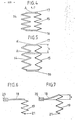
- Fig. 4 shows a schematic representation of a possible embodiment of the element 8 of Fig. 1 in the basic position (low temperature).
- This combined element consists of a compression spring 14 made of a shape memory alloy, which is capable of the two-way effect, and of a counter spring 15 designed as a tension spring.
- the two springs are each connected via a fixed plate 16 arranged below and an upper movable plate 17.
- the springs 14 and 15 can also be made in a different way, e.g. be arranged coaxially to each other.
- the force "F” exerted by this combination, which acts at point "A" is indicated by an arrow pointing upwards.
- FIG. 5 shows the combined element according to FIG. 4 in the position which results after the memory effect has been set. Due to the force exerted by the compression spring 14 on the movable plate 17, the point originally resting in "A” is now in "A '' '. The corresponding stroke” s "is indicated in the drawing by arrowheads.
- Fig. 6 shows a schematic representation of a combination ten element consisting of a spiral spring 18 made of a shape memory alloy and a tension spring designed as a tension spring 19 in the basic position (low temperature).
- the spiral spring 18 is totally clamped in the fixed piece 20, while the counter spring 19 is hooked into the fixed eyelet 21 at its lower end.
- FIG. 7 shows a schematic representation of the combined element according to FIG. 6 in the position after setting the memory effect (high temperature).
- the spiral spring 18 is curved upwards, so that its free end, on which the tension spring 19 engages, is increased by the stroke "s" compared to the basic position.
- the circuit breaker 2, 3 In the basic position, the circuit breaker 2, 3 is open and no current flows.
- the element 8 consisting. a spring made of memory alloy and a normal counter spring is at a temperature corresponding to the martensitic low-temperature phase, which is below the transition temperature M s .
- the push button 12 By briefly pressing (fraction of a second) the push button 12, the fixed contacts 2 of the circuit breaker are bridged by means of the movable contact piece 3 and the consumer 4 is connected to the mains.
- a current flows through the closed contacts 5 of the auxiliary switch and through the series resistor 7; which heats the element 8 either directly or indirectly within 100-500nsec-.
- the transition temperature is exceeded, the memory alloy tilts into the austenitic high-temperature phase, where it suddenly undergoes a considerable change in length.
- the element 8 expands in its longitudinal direction and pushes the switching pins 10 and 11 vertically upward via the crossmember 9.
- the temperature of element 8 has reached a value of 120-200 ° C, for example.
- the switching pin 10 presses the movable contact piece 3 of the circuit breaker against the contacts 2 and thus ensures that the power supply to the consumer 4 is maintained even after the pushbutton 12 has dropped off.
- the switching pin 11 opens the auxiliary switch and interrupts the power supply to the element 8. Further heating stops and the cooling process begins.
- the transition temperature eg approx.
- the element 8 contracts suddenly, with the switching pins 10 and 11 being pulled down over the crossmember 9.
- the movable contact piece 3 of the circuit breaker drops and interrupts the circuit.
- the contacts 5 of the auxiliary switch are closed.
- the starting position (basic position) according to FIG. 1 is thus restored.
- the cooling process takes, for example, in the present case, however, approximately 200 sec "can transition temperature, spring characteristics of the element 8 is set within certain limits by the physical data such as heat capacity, etc..
- the element 8 according to FIG. 1 essentially consisted of a compression spring 14 made of a memory alloy and a counter connected in parallel spring 15 (tension spring).
- the memory spring compression spring has the following characteristics:
- a resistance value of 3.3 ⁇ was chosen for the series resistor 7 (FIG. 1).
- the mains voltage was 220 V ⁇
- the heating-up time for the compression spring 14 until the memory effect was set was 100 msec.
- the spontaneous change in length (stroke "s") was 10 mm, the point "A” being raised under the influence of a force of 5 N to the point "A '".
- the value of 5 N relates to the excess force which, after deducting the force of the counter spring, was still available on average for actuating the switch.
- the temperature of the compression spring 14 was approximately 120 ° C.
- the time to reach the transition point of approximately 60 ° C. was 200 seconds. This time is determined by the cooling time plus the time which is necessary to supply the energy which brings about the conversion into the martensitic structure of the compression spring 14.
- the element 8 according to FIG. 1 essentially consisted of a spiral spring 18 made of a memory alloy with an insulated electrical heating element glued on and a counter spring 19 (tension spring).
- the spiral spring made of a memory alloy has the following characteristics:
- the mains voltage was 220 V ⁇
- the heating time for the spiral spring 18 until the memory effect was set to 500 msec.
- the spontaneous change in length (stroke "s") was 5 mm
- the mean excess force after deducting the force of the counter spring was 5 N.
- the temperature of the spiral spring 18 when the memory effect was set was 200 ° C.
- the corresponding temperature was 120 ° C.
- the device according to the invention made it possible to simplify the construction of timers where complicated mechanisms such as clockwork and the like are unnecessary. Thanks to the significant amplitude of the movement and the force of the memory effect as well as the hysteresis in function of the temperature, an accurate and reliable working of the device is guaranteed and maintenance is reduced.
Landscapes
- Thermally Actuated Switches (AREA)
Applications Claiming Priority (2)
| Application Number | Priority Date | Filing Date | Title |
|---|---|---|---|
| CH520680A CH627876A5 (de) | 1980-07-08 | 1980-07-08 | Zeitschalter. |
| CH5206/80 | 1980-07-08 |
Publications (1)
| Publication Number | Publication Date |
|---|---|
| EP0043604A1 true EP0043604A1 (fr) | 1982-01-13 |
Family
ID=4289705
Family Applications (1)
| Application Number | Title | Priority Date | Filing Date |
|---|---|---|---|
| EP81200626A Withdrawn EP0043604A1 (fr) | 1980-07-08 | 1981-06-09 | Commutateur temporisé |
Country Status (4)
| Country | Link |
|---|---|
| US (1) | US4371791A (fr) |
| EP (1) | EP0043604A1 (fr) |
| JP (1) | JPS5744934A (fr) |
| CH (1) | CH627876A5 (fr) |
Cited By (1)
| Publication number | Priority date | Publication date | Assignee | Title |
|---|---|---|---|---|
| DE3842171A1 (de) * | 1988-12-15 | 1990-06-28 | Barlian Reinhold | Verzoegerungsrelais |
Families Citing this family (5)
| Publication number | Priority date | Publication date | Assignee | Title |
|---|---|---|---|---|
| JPS6010299U (ja) * | 1983-06-30 | 1985-01-24 | クロイ電機株式会社 | 螢光灯点灯装置 |
| JPH0654093B2 (ja) * | 1985-03-12 | 1994-07-20 | マツダ株式会社 | 排気タ−ボ過給機付エンジン |
| US5160917A (en) * | 1990-06-14 | 1992-11-03 | Iowa State University Research Foundation, Inc. | Energy beam position detector |
| US5105178A (en) * | 1991-04-19 | 1992-04-14 | Krumme John F | Over-current/over-temperature protection device |
| FR2715763B1 (fr) * | 1994-02-01 | 1996-03-29 | Gec Alsthom T D Inc | Mécanisme d'actionnement d'une chambre de coupure de protection. |
Citations (2)
| Publication number | Priority date | Publication date | Assignee | Title |
|---|---|---|---|---|
| US3725835A (en) * | 1970-07-20 | 1973-04-03 | J Hopkins | Memory material actuator devices |
| US3959691A (en) * | 1973-04-16 | 1976-05-25 | Texas Instruments Incorporated | Motor protector |
Family Cites Families (3)
| Publication number | Priority date | Publication date | Assignee | Title |
|---|---|---|---|---|
| US3193711A (en) * | 1962-01-18 | 1965-07-06 | Collins Radio Co | Step-start circuit |
| US3371254A (en) * | 1965-10-01 | 1968-02-27 | Harold T. Hagfors | Safety control system |
| US3725644A (en) * | 1972-04-11 | 1973-04-03 | Barber Colman Co | Input switch for reversing the sense of an amplifier in a single loop heating-cooking system |
-
1980
- 1980-07-08 CH CH520680A patent/CH627876A5/de not_active IP Right Cessation
-
1981
- 1981-06-09 EP EP81200626A patent/EP0043604A1/fr not_active Withdrawn
- 1981-07-01 JP JP56101387A patent/JPS5744934A/ja active Pending
- 1981-07-06 US US06/280,487 patent/US4371791A/en not_active Expired - Fee Related
Patent Citations (2)
| Publication number | Priority date | Publication date | Assignee | Title |
|---|---|---|---|---|
| US3725835A (en) * | 1970-07-20 | 1973-04-03 | J Hopkins | Memory material actuator devices |
| US3959691A (en) * | 1973-04-16 | 1976-05-25 | Texas Instruments Incorporated | Motor protector |
Cited By (1)
| Publication number | Priority date | Publication date | Assignee | Title |
|---|---|---|---|---|
| DE3842171A1 (de) * | 1988-12-15 | 1990-06-28 | Barlian Reinhold | Verzoegerungsrelais |
Also Published As
| Publication number | Publication date |
|---|---|
| JPS5744934A (en) | 1982-03-13 |
| US4371791A (en) | 1983-02-01 |
| CH627876A5 (de) | 1982-01-29 |
Similar Documents
| Publication | Publication Date | Title |
|---|---|---|
| EP0363638A3 (fr) | Dispositif de commande pour interrupteur électrique | |
| EP0043604A1 (fr) | Commutateur temporisé | |
| DE60107264T2 (de) | Temperaturwächter für einen Flüssigkeitserhitzer | |
| DE2719446A1 (de) | Bimetallschutzschalter | |
| DE2065212A1 (de) | Elektrischer schalter | |
| DE604911C (de) | Anordnung zum Abschalten eines induktiven Widerstandes in einem Gleichstromkreis | |
| DE696668C (fr) | ||
| DE933472C (de) | Elektrothermisch betaetigter Periodenschalter | |
| AT374619B (de) | Thermischer schalter | |
| DE647699C (de) | Anordnung zum selbsttaetigen Betrieb elektrischer Widerstandsoefen, bei der die Heizwicklungen des Ofens durch einen Temperaturregler mit Verzoegerung von Dreieck- auf Sternschaltung umgeschaltet werden | |
| DE69708579T2 (de) | Überhitzungsanzeiger für Elektro-Haushaltsgerät | |
| DE733607C (de) | UEberstrom-UEberwachungseinrichtung | |
| CH391057A (de) | Bimetallschalter und Verwendung desselben | |
| DE457673C (de) | Selbsttaetiger Hoechststromschalter, dessen arbeitende Teile zwischen zwei parallelen Platten angeordnet sind | |
| DE488688C (de) | Vorrichtung zum selbsttaetigen Zu- und Abschalten eines Nebenstromkreises in Abhaengigkeit von der Belastung des Hauptstromkreises | |
| DE2150311A1 (de) | Temperaturabhaengiger elektrischer schalter mit einem bimetallischen steuerorgan | |
| DE1615222B2 (de) | Bimetallschalter zur einstellung und regelung der leistungsaufnahme von elektrischen kochplatten | |
| DE485361C (de) | Magnetisch-thermisches Ausloeserelais | |
| DE274881C (fr) | ||
| DE463907C (de) | Schnappschalter | |
| AT204934B (de) | Blinkrelais | |
| DE1538488C (de) | Einrichtung zur Überwachung der La dung einer Batterie mit einer bei aus reichender Generatorspannung erloschenden Signallampe, insbesondere fur Kraftfahr zeuge | |
| AT204623B (de) | Momentschalteinrichtung | |
| DE726679C (de) | Schwachstromgesteuerte Stufenschalteinrichtung fuer Starkstrom | |
| DE931059C (de) | Thermischer Ausloeser |
Legal Events
| Date | Code | Title | Description |
|---|---|---|---|
| PUAI | Public reference made under article 153(3) epc to a published international application that has entered the european phase |
Free format text: ORIGINAL CODE: 0009012 |
|
| AK | Designated contracting states |
Designated state(s): CH DE FR GB IT |
|
| 17P | Request for examination filed |
Effective date: 19820426 |
|
| STAA | Information on the status of an ep patent application or granted ep patent |
Free format text: STATUS: THE APPLICATION IS DEEMED TO BE WITHDRAWN |
|
| 18D | Application deemed to be withdrawn |
Effective date: 19831122 |
|
| RIN1 | Information on inventor provided before grant (corrected) |
Inventor name: MERCIER, OLIVIER, DR. |