EP0043983B1 - Brancard - Google Patents
Brancard Download PDFInfo
- Publication number
- EP0043983B1 EP0043983B1 EP81105082A EP81105082A EP0043983B1 EP 0043983 B1 EP0043983 B1 EP 0043983B1 EP 81105082 A EP81105082 A EP 81105082A EP 81105082 A EP81105082 A EP 81105082A EP 0043983 B1 EP0043983 B1 EP 0043983B1
- Authority
- EP
- European Patent Office
- Prior art keywords
- stretcher
- stretcher according
- safety belt
- patient
- restraining
- Prior art date
- Legal status (The legal status is an assumption and is not a legal conclusion. Google has not performed a legal analysis and makes no representation as to the accuracy of the status listed.)
- Expired
Links
Images

Classifications
-
- A—HUMAN NECESSITIES
- A61—MEDICAL OR VETERINARY SCIENCE; HYGIENE
- A61G—TRANSPORT, PERSONAL CONVEYANCES, OR ACCOMMODATION SPECIALLY ADAPTED FOR PATIENTS OR DISABLED PERSONS; OPERATING TABLES OR CHAIRS; CHAIRS FOR DENTISTRY; FUNERAL DEVICES
- A61G1/00—Stretchers
- A61G1/04—Parts, details or accessories, e.g. head-, foot-, or like rests specially adapted for stretchers
-
- A—HUMAN NECESSITIES
- A61—MEDICAL OR VETERINARY SCIENCE; HYGIENE
- A61F—FILTERS IMPLANTABLE INTO BLOOD VESSELS; PROSTHESES; DEVICES PROVIDING PATENCY TO, OR PREVENTING COLLAPSING OF, TUBULAR STRUCTURES OF THE BODY, e.g. STENTS; ORTHOPAEDIC, NURSING OR CONTRACEPTIVE DEVICES; FOMENTATION; TREATMENT OR PROTECTION OF EYES OR EARS; BANDAGES, DRESSINGS OR ABSORBENT PADS; FIRST-AID KITS
- A61F5/00—Orthopaedic methods or devices for non-surgical treatment of bones or joints; Nursing devices ; Anti-rape devices
- A61F5/37—Restraining devices for the body or for body parts; Restraining shirts
- A61F5/3769—Restraining devices for the body or for body parts; Restraining shirts for attaching the body to beds, wheel-chairs or the like
- A61F5/3776—Restraining devices for the body or for body parts; Restraining shirts for attaching the body to beds, wheel-chairs or the like by means of a blanket or belts
-
- A—HUMAN NECESSITIES
- A61—MEDICAL OR VETERINARY SCIENCE; HYGIENE
- A61G—TRANSPORT, PERSONAL CONVEYANCES, OR ACCOMMODATION SPECIALLY ADAPTED FOR PATIENTS OR DISABLED PERSONS; OPERATING TABLES OR CHAIRS; CHAIRS FOR DENTISTRY; FUNERAL DEVICES
- A61G1/00—Stretchers
- A61G1/02—Stretchers with wheels
- A61G1/0206—Stretchers with wheels characterised by the number of supporting wheels if stretcher is extended
- A61G1/0212—2 pairs having wheels within a pair on the same position in longitudinal direction, e.g. on the same axis
-
- A—HUMAN NECESSITIES
- A61—MEDICAL OR VETERINARY SCIENCE; HYGIENE
- A61G—TRANSPORT, PERSONAL CONVEYANCES, OR ACCOMMODATION SPECIALLY ADAPTED FOR PATIENTS OR DISABLED PERSONS; OPERATING TABLES OR CHAIRS; CHAIRS FOR DENTISTRY; FUNERAL DEVICES
- A61G1/00—Stretchers
- A61G1/02—Stretchers with wheels
- A61G1/0231—Stretchers with wheels having only fixed wheels
-
- A—HUMAN NECESSITIES
- A61—MEDICAL OR VETERINARY SCIENCE; HYGIENE
- A61G—TRANSPORT, PERSONAL CONVEYANCES, OR ACCOMMODATION SPECIALLY ADAPTED FOR PATIENTS OR DISABLED PERSONS; OPERATING TABLES OR CHAIRS; CHAIRS FOR DENTISTRY; FUNERAL DEVICES
- A61G1/00—Stretchers
- A61G1/04—Parts, details or accessories, e.g. head-, foot-, or like rests specially adapted for stretchers
- A61G1/042—Suspension means
Definitions
- the invention relates to a stretcher with an adjustable and lockable belt that serves as a seat belt for holding a patient lying on the stretcher.
- the invention further relates to a restraint cushion with which a conventional stretcher can be retrofitted to an inventive one.
- a so-called shoulder sloping belt for a stretcher has already been developed (cf. DE-C-2 543 473), which is guided obliquely over a patient's shoulder.
- This sloping shoulder belt is attached to the head of the stretcher so that the shoulder of the patient in question is at least 20 cm from the head of the stretcher. This distance of 20 cm is even a lower limit for the measurement from a patient's shoulder to the head end.
- the inventor had already considered attaching the seat belt at shoulder height, but this could entail certain disadvantages for the patient with regard to narrowing the lying surface; additional injuries as a result of such a restriction could not be ruled out.
- the seat belt could also be attached below the stretcher, not at the head end. For this, however, the seat belt would have to be passed through the stretcher cover and its support.
- the pad should be removable, it would be cumbersome and time consuming to constantly re-insert the seat belt into the stretcher cover and pad.
- the support and the stretcher cover would have to be provided with appropriate openings.
- This object is achieved according to the invention in that a restraint cushion is held on the stretcher, which rests on a restraint surface on the shoulder of the patient, so that the stretcher remains stationary with respect to the stretcher even in the case of abrupt movements in its longitudinal direction.
- a bulge is preferably provided in the restraint cushion for the patient's head and neck.
- the restraint cushion is advantageously integrated with the seat belt, wherein a further seat belt can be provided and the seat belt and the further seat belt are each guided over one shoulder of the patient.
- the seat belt and the further seat belt are fastened at one end to the restraint cushion and at the other end to side rails of the head end of the stretcher.
- the other end of the seat belt and the further seat belt can be attached to the side rails at the level of a fastening belt running transversely to the longitudinal direction of the stretcher. It is also possible that the seat belt and the additional seat belt are attached directly to the fastening belt.
- At least one belt is used to attach the restraint cushion to the stretcher.
- the belt and possibly a further belt can each be fastened to a side rail of the head end of the stretcher.
- the seat belt and, if applicable, the additional seat belt can be attached to the restraint cushion via an automatic housing.
- the length of the seat belts and the straps used to attach the restraint cushion are adjustable.
- the restraining cushion on the stretcher is elastically mounted so that an abrupt interception of the Patients with the jerky movements are avoided.
- Such an elastic mounting of the restraint cushion gently absorbs the inertial forces that occur when the patient collides; in addition, the stretcher according to the invention makes the work of the paramedic considerably easier, since the retaining cushion does not first have to be removed in order to cover the mattress with a blanket or a paper cover.
- the restraint cushion can also be attached to existing stretchers or other vehicles without major modifications.
- the retention cushion is therefore not secure integrated seat belt; rather, it is supported elastically, for which purpose a spring can serve, for example.
- This spring can in turn be arranged on a rod.
- the linkage with the spring can advantageously be integrated with the retention cushion.
- the linkage can preferably be anchored at the head end of the stretcher. It has two piston rods running in the longitudinal direction of the stretcher, on each of which a piston housing slides with a spring.
- the two piston housings can be rigidly connected to one another by a plate.
- the linkage or the spring mechanism is located below the actual cushion.
- the linkage can be attached to the underside of a wooden plate reinforced with reinforcing straps, on the upper side of which there is a molded hard foam molded part which is covered with soft foam in the head region.
- the hard foam molding is provided with the soft foam with a synthetic leather cover that is attached to the lower edge of the board.
- a cushion of the restraint cushion prevents a patient's body from slipping over the restraint cushion, which does not require the use of seat belts due to the mobility of the restraint cushion over the stroke length of the piston rods.
- an even greater security against injuries to a patient carried on such a stretcher can be achieved in that the restraint cushion is attached to a holding belt, that a safety belt with automatic retraction and a coupling part is provided, and that a corresponding second coupling part is provided on the vehicle floor, in which the coupling part of the safety belt automatically hooks into the stretcher when loading the stretcher and that the holding belt is connected to the automatic retractor in such a way that a tensile force in the holding belt blocks the automatic retractor.
- the seat belt with its coupling is releasably connected to the vehicle floor when loading the stretcher.
- the belt connected to the automatic reel-up device and the restraint cushion pulls the lock of the automatic reel-up mechanism in the event of a jerky movement of the restraint cushion forward, so that the seat belt connected to the vehicle floor is locked and the patient is held to the vehicle floor with the stretcher.
- a particular advantage of the solution outlined above is that in facilities where the stretcher can be brought forward or lowered to the head, the automatic rewinder enables such normal movements and only locks in the event of sudden changes, for example when braking or in an accident.
- the invention can be further developed in that the automatic reel-up is arranged on a cross member of the stretcher in the area of the foot end. This ensures that the safe coupling of the seat belt to the vehicle floor can be checked easily and conveniently during loading.
- a particularly preferred embodiment according to the invention is created in that the holding belt is arranged running underneath the lying surface of the stretcher.
- the tether is forked laterally in the area of the head end of the stretcher and has fastenings on both sides of the restraint cushion. This ensures a particularly stable retention of the restraint cushion.
- the fasteners are preferably detachable, for example to cover or the like. easy to replace.
- a particularly preferred embodiment according to the invention can be created in that the coupling part of the seat belt is designed as a holding loop and that the coupling part or the like on the vehicle floor as a hook. is formed, in which the hand strap hooks automatically.
- An embodiment according to the invention can be created in that the tether is connected directly to the lock of the automatic reel-up.
- the holding belt is advantageous for the holding belt to be forked up and down in the area of the foot end of the stretcher, one section of the fork being connected to the lock and the other section absorbing the tensile forces.
- a particularly preferred embodiment is created in that the holding belt is designed forked up and down in the area of the foot end of the stretcher, that the two sections of the fork are firmly connected to the housing of the automatic retractor and that one of the sections is arranged such that a change in the angle between the sections triggers the lock of the automatic retractor.
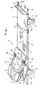
- FIG 1 shows an embodiment of a stretcher 1, as is preferably used in ambulances.
- the stretcher 1 consists of a support frame 2, between which a support surface extends freely, on which a patient, not shown, comes to lie.
- the support surface 3 generally consists of a cloth which is attached to the support frame.
- the support frame 2 itself consists of longitudinal spars 4, 5, which are formed from cylindrical hollow tubes. The hollow tubes can have a different cross section.
- extendable carrying handles are accommodated in the longitudinal spars 4, 5, which carry head-like end pieces 8a at their ends, which prevent the carrying handles from being pushed too deep into the longitudinal spars 4, 5.
- the pull-out handles are also provided with stops, not shown, which prevent handles from being pulled out of the longitudinal bars 4, 5 completely.
- Wheels 30 are located at the lower ends of the holding arms 9. In the illustrated case, the wheels 30 are fastened on axles 31 which extend between the pairs of holding arms 9 at the head end 6 and at the foot end 7 and are held in these.
- the stretcher 1 shown in Figure 1 also includes an upward folding backrest 26, which consists of two side rails 15 connected at their ends to a bracket 27 (only one side rail 15 is shown), between which part of the support surface 3 extends.
- the lower ends of the side rails 15 are pivotally supported in connecting links 28, which in turn are fastened to the longitudinal rails 4 and 5.
- a bracket 20 which forms a footrest for the patient on the stretcher 1, and a fastening strap 24, which serves to fix the legs of the patient.
- a fastening belt 23 is provided between the bars 15, which holds the patient in the region of his upper body.
- two seat belts 10, 13 each lead via fastening devices 40, 43, which are preferably designed as quick snap-in connections, over one shoulder of the patient to the underside of a restraint cushion 11.
- the seat belts 10, 13 are fastened to the restraint cushion 11 via an automatic housing 18 (see FIG. 2).
- the safety cushion 11 contains a bulge 12 into which the patient's head and neck can be received.
- the fastening belt 23 is also passed over the upper body of the patient.
- the connecting devices 40, 43 can be provided on this fastening belt 23.
- straps 16, 17 are provided which, like the straps 10, 13, can be adjusted in length via buckles 44, 45. These straps 16, 17 are attached to a base 46 of the restraint cushion 11, on which the automatic housing 18 is also fixed. In contrast to the retaining cushion 11, this support 46 is rigid. Furthermore, the straps 16, 17 can be fastened to the bars 15 of the backrest 26, which is adjustable in height via a linkage 47.
- the restraining surface 19 of the restraining cushion 11 absorbs the inertial force exerted by the patient by means of the safety belts 10, 13, so that the patient behaves in a stationary manner with respect to the stretcher 1. As a result, injuries to the patient due to jerky movements of the stretcher 1 are largely avoided.
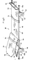
- the stretcher 101 shown in Fig. 3 consists of a support frame 102, between which a support surface 103 extends freely, on which a patient, not shown, comes to lie.
- the support surface 103 generally consists of a cloth which is attached to the support frame 102.
- the support frame 102 itself has longitudinal spars 104, 105, which are formed from cylindrical hollow tubes. The hollow tubes can have a different cross section.
- extendable carrying handles are accommodated in the longitudinal spars 104, 105, which carry head-like end pieces 108a at their ends, which prevent the carrying handles from being pushed too deep into the longitudinal spars 104, 105.
- the extendable handles are also provided with stops, not shown, which prevent the handles from the longitudinal bars 104, 105 completely can be pulled out.
- Wheels 130 are located at the lower ends of the holding arms 109. In the exemplary embodiment shown, the wheels 130 are fastened on axes 131 which extend between the pairs of holding arms 109 at the head end 106 and at the foot end 107 and are held in these.
- the stretcher shown in Fig. 3 also has an upward folding backrest 126, which has 102 brackets 140 at its upper end into which tubes can be inserted.
- the backrest 126 is pivotally supported in connecting members 128, which in turn are fastened to the longitudinal bars 104 and 105.
- a bracket 120 which forms a footrest for the patient on the stretcher 101, and a fastening strap 124, which serves to secure the patient's legs, also extend between the longitudinal spars 104, 105.
- a fastening belt 123 is also provided on the backrest 126, which holds the patient in the region of his upper body.
- the backrest 126 itself is height-adjustable via a linkage 147.
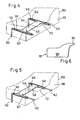
- FIG. 4 now shows the restraint cushion for the stretcher according to FIG. 3.
- This restraint cushion has two piston rods 141, 142, which can be inserted into the openings of the holder 140 via their downwardly bent ends 143, 144.
- a spring 145, 146 is provided on each of the piston rods 141, 142.
- a piston housing 147, 148 slides on the piston rods 141, 142 behind the springs 145, 146.
- the piston housings 147, 148 are connected to one another by a plate 149.
- the diameter of the piston housing 147, 148 is selected such that the spring 145 or 146 can be compressed by this piston housing, as shown in FIG. 5.
- the piston rods 141, 142, the springs 145, 146 and the piston housings 147, 148 thus form shock absorbers, which are shown in FIG. 4 in the relaxed state and in FIG. 5 in the tensioned state.
- the retention cushion 111 contains a bulge 112 lined with soft foam in a rigid foam molded part 150, which is shown in broken lines in FIGS. The patient's head and neck are received in this bulge 112. If a patient is on the stretcher 101, then his shoulders lie against a “hard” restraint surface 119 of the restraint cushion 111, the belt 123 being guided over the upper body of the patient.
- the molded part 150 is attached to a board, not shown, on the possibly reinforced underside of which the linkage 141, 142 is attached.
- the molded part 150 is covered with synthetic leather, which is attached to the underside of the board.
- the board can be made of wood or plastic.
- FIG. 6 shows a side view of the restraint cushion with a cushion stem 151 of the cushion filling 150.
- This cushion stem 151 prevents the body of a patient from sliding over the restraint cushion 111, because of the mobility of the restraint cushion 111 over the stroke length of the piston rods 141, 142 in a special way Seat belts for the restraint cushion 111 are dispensed with.
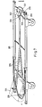
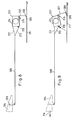
- FIG. 7 shows a schematic perspective view of a further exemplary embodiment of a stretcher according to the invention, only the frame of the stretcher 201 being illustrated and the lying surface being omitted.
- an automatic retractor 203 of a seat belt 207 is pivotably mounted about an axis 215 on a rear cross member 202 in the area of the foot end of the stretcher 201.
- the automatic reel-up device 203 is connected to the restraining cushion 204 by means of a holding belt 205 which is forked in a horizontal plane in the front region in the direction of the head end of the stretcher 201.
- the two legs of the crotch of the tether 205 are laterally anchored to fastenings 206 with the restraint cushion.
- the fasteners 206 are preferably designed to be detachable in order to be able to easily replace the cushion 204 or its cover.
- the tether 205 runs below the lying surface (not shown) of the stretcher 201.
- the seat belt 207 has a coupling part 208, which in the illustrated embodiment is designed as a holding loop.
- a corresponding coupling part 209 is provided on the floor 211 of the ambulance, the illustrated embodiment being a hook-shaped projection 209.
- the automatic reel-up device 203 is set such that the rolled-up length of the seat belt 207 is limited in such a way that the holding loop 208 is located at a short distance above the vehicle floor 211 in the rolled-up state.
- the stretcher 201 is pushed into the carrier rails (not shown) in the vehicle, the holding loop 208 therefore automatically hooks into the holder 209.
- the tether 205 is forked in the vertical plane in the area of the automatic reel and connected to the housing of the automatic reel in such a way that when the tether 205 is tightened, the lock 210 of the automatic reel is actuated.
- FIGS. 8 and 9 This mode of operation is illustrated in FIGS. 8 and 9, with braking of the vehicle being indicated by the arrow 216 in FIG. 9.
- the two sections 212 and 213 of the vertical fork of the tether 205 are fixed to the housing 214 of the retractor maten 203 connected, the arrangement being such (see FIG. 9) that when the stretcher 201 moves in the direction of the arrow 216, the resulting change in angle between the sections 212 and 213 locks the lock 210 on the automatic reel 203. Since, when the vehicle brakes and a certain deceleration value is exceeded, the holding belt 205 is pulled forward by the stretcher 201 in the direction of the arrow 216, the lock 210 is pivoted upwards by the lower section 213 and the seat belt is locked.
- either the tether 205 can be connected directly to the lock 210 or one of the sections 212 or 213 to the lock 210.
- the pillow 204 is designed to be usable on both sides, preferably one side of the pillow 204 being provided with a head recess, while the opposite side is smoothly padded.
Landscapes
- Health & Medical Sciences (AREA)
- Life Sciences & Earth Sciences (AREA)
- Animal Behavior & Ethology (AREA)
- General Health & Medical Sciences (AREA)
- Public Health (AREA)
- Veterinary Medicine (AREA)
- Nursing (AREA)
- Orthopedic Medicine & Surgery (AREA)
- Engineering & Computer Science (AREA)
- Biomedical Technology (AREA)
- Heart & Thoracic Surgery (AREA)
- Vascular Medicine (AREA)
- Invalid Beds And Related Equipment (AREA)
- Seats For Vehicles (AREA)
Claims (37)
Applications Claiming Priority (6)
| Application Number | Priority Date | Filing Date | Title |
|---|---|---|---|
| DE19803026406 DE3026406C2 (de) | 1980-07-11 | 1980-07-11 | Krankentrage |
| DE3026406 | 1980-07-11 | ||
| DE19803041932 DE3041932A1 (de) | 1980-11-06 | 1980-11-06 | Krankentrage |
| DE3041932 | 1980-11-06 | ||
| DE3124416 | 1981-06-22 | ||
| DE19813124416 DE3124416A1 (de) | 1981-06-22 | 1981-06-22 | Krankentrage mit einem verstellbaren und arretierbaren gurt |
Publications (3)
| Publication Number | Publication Date |
|---|---|
| EP0043983A2 EP0043983A2 (fr) | 1982-01-20 |
| EP0043983A3 EP0043983A3 (en) | 1982-02-03 |
| EP0043983B1 true EP0043983B1 (fr) | 1986-03-12 |
Family
ID=27188772
Family Applications (1)
| Application Number | Title | Priority Date | Filing Date |
|---|---|---|---|
| EP81105082A Expired EP0043983B1 (fr) | 1980-07-11 | 1981-07-01 | Brancard |
Country Status (4)
| Country | Link |
|---|---|
| US (1) | US4534075A (fr) |
| EP (1) | EP0043983B1 (fr) |
| DK (1) | DK156293C (fr) |
| WO (1) | WO1982000247A1 (fr) |
Families Citing this family (45)
| Publication number | Priority date | Publication date | Assignee | Title |
|---|---|---|---|---|
| EP0165043A3 (fr) * | 1984-06-11 | 1987-05-27 | David Anthony Brooks | Dispositif de retenue de sécurité pour enfants |
| US4695072A (en) * | 1985-07-02 | 1987-09-22 | Norman D. Koerner | Athlete carrier |
| US4945583A (en) * | 1987-03-17 | 1990-08-07 | Alois Schnitzler | Device for transporting disabled or sick persons |
| US4977630A (en) * | 1987-06-25 | 1990-12-18 | Oswalt James A | Patient mover |
| US5016299A (en) * | 1989-05-23 | 1991-05-21 | Claude Boulanger | Emergency evacuation harness |
| US5860176A (en) * | 1997-09-24 | 1999-01-19 | Norberg; William J. | Pediatric critical care transport system |
| US6916056B2 (en) * | 2002-10-18 | 2005-07-12 | Godby Enterprises, Llc | Bariatric gurney and process |
| US7120950B2 (en) * | 2004-07-20 | 2006-10-17 | Goodway Industrial (H.K.) Ltd. | Hybrid mattress |
| ATE516909T1 (de) * | 2007-09-04 | 2011-08-15 | Mapal Fab Praezision | Reibahle |
| DE102010005619B4 (de) * | 2010-01-25 | 2021-01-28 | Marion Mohr | Krankentragenauflage mit integriertem Kinder-Rückhaltesystem |
| US8602953B2 (en) | 2011-02-04 | 2013-12-10 | Amy Christine Jordan | Reformer apparatus having integral ergonomic purchase translatable into deployed and stowed positions |
| US9022706B2 (en) | 2011-12-13 | 2015-05-05 | Stryker Corporation | Energy absorbing fastening system |
| US9044364B2 (en) | 2012-07-17 | 2015-06-02 | Eripio, Llc | Portable human transport system |
| US9603764B2 (en) | 2014-02-11 | 2017-03-28 | Medline Industries, Inc. | Method and apparatus for a locking caster |
| US10245209B2 (en) | 2014-02-19 | 2019-04-02 | Keith G. Lurie | Systems and methods for gravity-assisted cardiopulmonary resuscitation |
| US11844742B2 (en) | 2014-02-19 | 2023-12-19 | Keith G. Lurie | Methods and systems to reduce brain damage |
| US10406069B2 (en) | 2014-02-19 | 2019-09-10 | Keith G. Lurie | Device for elevating the head and chest for treating low blood flow states |
| US10350137B2 (en) | 2014-02-19 | 2019-07-16 | Keith G. Lurie | Elevation timing systems and methods for head up CPR |
| US11259988B2 (en) | 2014-02-19 | 2022-03-01 | Keith G. Lurie | Active compression decompression and upper body elevation system |
| US11246794B2 (en) | 2014-02-19 | 2022-02-15 | Keith G. Lurie | Systems and methods for improved post-resuscitation recovery |
| US10667987B2 (en) | 2014-02-19 | 2020-06-02 | Keith G. Lurie | Uniform chest compression CPR |
| US9801782B2 (en) | 2014-02-19 | 2017-10-31 | Keith G. Lurie | Support devices for head up cardiopulmonary resuscitation |
| US11096861B2 (en) | 2014-02-19 | 2021-08-24 | Keith G. Lurie | Systems and methods for gravity-assisted cardiopulmonary resuscitation and defibrillation |
| US9707152B2 (en) | 2014-02-19 | 2017-07-18 | Keith G. Lurie | Systems and methods for head up cardiopulmonary resuscitation |
| US9750661B2 (en) | 2014-02-19 | 2017-09-05 | Keith G. Lurie | Systems and methods for head up cardiopulmonary resuscitation |
| US12144777B2 (en) | 2014-02-19 | 2024-11-19 | Resuscitation Innovations Llc | Methods and systems to reduce brain damage |
| US10406068B2 (en) | 2014-02-19 | 2019-09-10 | Keith G. Lurie | Lockable head up cardiopulmonary resuscitation support device |
| US11020314B2 (en) | 2014-02-19 | 2021-06-01 | Keith G. Lurie | Methods and systems to reduce brain damage |
| DE102014205837B4 (de) * | 2014-03-28 | 2017-07-06 | Siemens Healthcare Gmbh | Medizinische Sicherungseinheit, medizinische Zubehöreinheit, Patientenlagerungsvorrichtung sowie eine medizinische Bildgebungsvorrichtung |
| US20170014285A1 (en) * | 2014-04-05 | 2017-01-19 | Gayathree Mohan | Emergency mobile labor cot inside ambulance vans |
| US20180000665A1 (en) | 2014-07-09 | 2018-01-04 | Rx 1186, LLC | Spine board with interior channels |
| ES2959494T3 (es) * | 2014-10-01 | 2024-02-26 | Ferno Washington | Camilla o litera modular |
| CN104382700B (zh) * | 2014-11-24 | 2017-03-08 | 广西水利电力职业技术学院 | 一种自动平衡担架 |
| CN104605997A (zh) * | 2015-02-05 | 2015-05-13 | 张家港市协和医疗器械有限公司 | 一种急救专用担架 |
| US9959756B2 (en) | 2015-10-01 | 2018-05-01 | Here Global B.V. | Transmission of targeted roadway alerts |
| US10749807B2 (en) | 2016-08-30 | 2020-08-18 | Here Global B.V. | Wireless network optimization |
| US10080693B1 (en) * | 2017-04-26 | 2018-09-25 | Stryker Corporation | Harness system for patient transport apparatus |
| CN107260379B (zh) * | 2017-07-07 | 2018-02-02 | 李现军 | 颈椎牵引式担架 |
| CN107184319B (zh) * | 2017-07-14 | 2018-09-14 | 郭林平 | 急救用担架及方法 |
| CA2992072A1 (fr) * | 2017-09-18 | 2019-03-18 | Rx 1186, LLC | Plaque de colonne dotee de canaux interieurs |
| US12342881B1 (en) | 2018-10-08 | 2025-07-01 | Tracy A. White | Disposable wrist securing device with escape feature system and method |
| ES1234714Y (es) * | 2019-07-15 | 2019-12-11 | Diseno Y Produccion De Sist Rcp S L | Dispositivo para la reanimacion cardio-pulmonar de un paciente |
| US12201561B2 (en) | 2020-03-31 | 2025-01-21 | Michael Fonte | Elevated CPR assist device and method |
| CN114681184B (zh) * | 2022-05-18 | 2022-08-12 | 首都医科大学宣武医院 | 功能神外患者外出检查头部固定装置 |
| DE102023133176A1 (de) * | 2023-11-28 | 2025-05-28 | Reha & Medi Hoffmann Gmbh | Vorrichtung zum Stabilisieren, Immobilisieren und/oder Fixieren eines Kopfes |
Family Cites Families (29)
| Publication number | Priority date | Publication date | Assignee | Title |
|---|---|---|---|---|
| CA611065A (en) * | 1960-12-20 | Paul Goodwin | Shoulder harnesses | |
| DE129622C (fr) * | ||||
| US1874613A (en) * | 1930-02-03 | 1932-08-30 | Joseph H Pilates | Chair |
| US2033779A (en) * | 1934-04-14 | 1936-03-10 | Tor Equipment Company Ltd | Ambulance stretcher |
| US2191097A (en) * | 1939-03-13 | 1940-02-20 | Gordon M Morrison | Splint stretcher |
| US2309464A (en) * | 1941-09-02 | 1943-01-26 | Joseph P Lucci | Safety carrier |
| US2361328A (en) * | 1943-09-03 | 1944-10-24 | Kenneth F Springer | Headpiece for litters |
| US2666476A (en) * | 1949-08-15 | 1954-01-19 | Bertha C Lycan | Auto seat headrest |
| US2973029A (en) * | 1958-06-16 | 1961-02-28 | Clifford F Schlosstein | Passenger safety equipment for automobile |
| US3204256A (en) * | 1962-12-20 | 1965-09-07 | Stollenwerk Hans | Patient securing belts for stretchers |
| US3347544A (en) * | 1965-03-01 | 1967-10-17 | Uffenorde Tui Marie | Headrest for eye surgery |
| US3561817A (en) * | 1968-06-20 | 1971-02-09 | Leo Austin Needham | Safety harness assembly |
| US3566422A (en) * | 1969-01-23 | 1971-03-02 | Allen P Klippel | Spine board apparatus for rescue of fracture patients and the like |
| US3707734A (en) * | 1971-03-17 | 1973-01-02 | M Matthews | Universal spine and splinting board |
| US3732863A (en) * | 1971-04-14 | 1973-05-15 | W Harrington | Stretcher |
| US3779599A (en) * | 1971-07-08 | 1973-12-18 | A Gottfried | Juvenile seating system |
| US3737923A (en) * | 1971-09-27 | 1973-06-12 | D Prolo | Cervical stabilization device |
| US3918760A (en) * | 1972-03-16 | 1975-11-11 | Morris I Goldberg | Guard rail safety lock |
| US3887233A (en) * | 1972-08-22 | 1975-06-03 | Nasa | Shoulder harness and lap belt restraint system |
| US3819197A (en) * | 1972-12-05 | 1974-06-25 | Gen Motors Corp | Semirigid shoulder belts |
| US4064574A (en) * | 1974-11-09 | 1977-12-27 | Alois Schnitzler | Stretcher |
| US4034748A (en) * | 1975-10-28 | 1977-07-12 | Winner Stephen E | Spinal restraint device |
| US4074373A (en) * | 1976-02-06 | 1978-02-21 | F. Garofalo Electric Co., Inc. | System for attaching pillow to X-ray table |
| US4151842A (en) * | 1976-10-18 | 1979-05-01 | Miller Larry C | Body splint/litter device |
| DE2710591A1 (de) * | 1977-03-11 | 1978-09-14 | Klippan Gmbh | Doppelschulter-beckengurt |
| US4124908A (en) * | 1977-10-06 | 1978-11-14 | Burns Oliver E | Rescue and transportation device |
| US4204529A (en) * | 1978-01-03 | 1980-05-27 | William Cochrane | Cervical collar apparatus |
| DE2810577A1 (de) * | 1978-03-11 | 1979-09-20 | Volkswagenwerk Ag | Fahrzeug, insbesondere personenkraftfahrzeug |
| FR2437824A1 (fr) * | 1978-10-03 | 1980-04-30 | Condor | Oreiller orthopedique |
-
1981
- 1981-06-30 WO PCT/DE1981/000103 patent/WO1982000247A1/fr not_active Ceased
- 1981-06-30 US US06/361,906 patent/US4534075A/en not_active Expired - Lifetime
- 1981-07-01 EP EP81105082A patent/EP0043983B1/fr not_active Expired
-
1982
- 1982-02-04 DK DK047382A patent/DK156293C/da not_active IP Right Cessation
Also Published As
| Publication number | Publication date |
|---|---|
| EP0043983A3 (en) | 1982-02-03 |
| WO1982000247A1 (fr) | 1982-02-04 |
| DK156293C (da) | 1989-12-18 |
| EP0043983A2 (fr) | 1982-01-20 |
| DK47382A (da) | 1982-02-04 |
| DK156293B (da) | 1989-07-31 |
| US4534075A (en) | 1985-08-13 |
Similar Documents
| Publication | Publication Date | Title |
|---|---|---|
| EP0043983B1 (fr) | Brancard | |
| EP0911008B1 (fr) | Dispositif d'assise déplaçable | |
| DE2551419C3 (de) | Vorrichtung zum Sichern von Insassen in Kraftfahrzeugen | |
| DE2917798A1 (de) | Kindersitzanordnung fuer ein fahrzeug | |
| DE2514769C3 (de) | Kindersitz für Kraftfahrzeuge | |
| DE3230428A1 (de) | Sicherheitsliege fuer kleinkinder | |
| DE3643367A1 (de) | Einrichtung zum ausueben einer spinalen streckkraft | |
| DE2519461A1 (de) | Zerlegbare, unter einen patienten oder verletzten schiebbare tragbahre und befreiungs- oder rettungsvorrichtung | |
| WO1982001171A1 (fr) | Siege d'enfant pour vehicule automobile | |
| CH656538A5 (de) | Sicherheitsgurt-system fuer eine krankentrage. | |
| DE3204665A1 (de) | Rueckhaltesystem fuer einen rollstuhl und den rollstuhlfahrer in einem fahrzeug | |
| DE2147248C2 (de) | Schalenförmiger Kindersitz für Fahrzeuge, insbesondere Kraftwagen | |
| EP1318782B1 (fr) | Civière équipée d'un système de retenue de patient, notamment destinée aux personnes en position couchée | |
| EP1394003A2 (fr) | Dispositif de retenue | |
| DE4342959A1 (de) | Fahrzeugsitz | |
| DE3026406C2 (de) | Krankentrage | |
| DE10058346A1 (de) | Krankentrage mit Patienten-Rückhaltesystem für liegende Personen | |
| DE102007048406B4 (de) | Kindersitz zum Einbau in ein Fahrzeug entgegen dessen Fahrtrichtung | |
| EP0603520B1 (fr) | Siège de sécurité pour enfant | |
| DE2218254A1 (de) | Sitz für Kraftfahrzeuge | |
| DE202014011176U1 (de) | Sicherheitsgurt-Clip | |
| DE296369C (fr) | ||
| DE20213310U1 (de) | Rückhaltesystem | |
| DE102013108425B4 (de) | Verlagerbarer Kindersitz | |
| DE3041932A1 (de) | Krankentrage |
Legal Events
| Date | Code | Title | Description |
|---|---|---|---|
| PUAI | Public reference made under article 153(3) epc to a published international application that has entered the european phase |
Free format text: ORIGINAL CODE: 0009012 |
|
| PUAL | Search report despatched |
Free format text: ORIGINAL CODE: 0009013 |
|
| AK | Designated contracting states |
Designated state(s): BE FR GB IT LU NL |
|
| AK | Designated contracting states |
Designated state(s): BE FR GB IT LU NL |
|
| TCNL | Nl: translation of patent claims filed | ||
| ITCL | It: translation for ep claims filed |
Representative=s name: DR. ING. A. RACHELI & C. |
|
| 17P | Request for examination filed |
Effective date: 19820630 |
|
| GRAA | (expected) grant |
Free format text: ORIGINAL CODE: 0009210 |
|
| AK | Designated contracting states |
Kind code of ref document: B1 Designated state(s): BE FR GB IT LU NL |
|
| ITF | It: translation for a ep patent filed | ||
| ET | Fr: translation filed | ||
| PLBE | No opposition filed within time limit |
Free format text: ORIGINAL CODE: 0009261 |
|
| STAA | Information on the status of an ep patent application or granted ep patent |
Free format text: STATUS: NO OPPOSITION FILED WITHIN TIME LIMIT |
|
| 26N | No opposition filed | ||
| ITTA | It: last paid annual fee | ||
| EPTA | Lu: last paid annual fee | ||
| PGFP | Annual fee paid to national office [announced via postgrant information from national office to epo] |
Ref country code: GB Payment date: 20001221 Year of fee payment: 20 |
|
| PGFP | Annual fee paid to national office [announced via postgrant information from national office to epo] |
Ref country code: FR Payment date: 20001229 Year of fee payment: 20 |
|
| PGFP | Annual fee paid to national office [announced via postgrant information from national office to epo] |
Ref country code: NL Payment date: 20001231 Year of fee payment: 20 |
|
| BE20 | Be: patent expired |
Free format text: 20010701 *CHRISTIAN MIESSEN FAHRZEUG- UND KAROSSERIEWERK G.M.B.H. |
|
| PGFP | Annual fee paid to national office [announced via postgrant information from national office to epo] |
Ref country code: BE Payment date: 20010108 Year of fee payment: 20 |
|
| PGFP | Annual fee paid to national office [announced via postgrant information from national office to epo] |
Ref country code: LU Payment date: 20010109 Year of fee payment: 20 |
|
| PG25 | Lapsed in a contracting state [announced via postgrant information from national office to epo] |
Ref country code: GB Free format text: LAPSE BECAUSE OF EXPIRATION OF PROTECTION Effective date: 20010630 |
|
| PG25 | Lapsed in a contracting state [announced via postgrant information from national office to epo] |
Ref country code: NL Free format text: LAPSE BECAUSE OF EXPIRATION OF PROTECTION Effective date: 20010701 Ref country code: LU Free format text: LAPSE BECAUSE OF EXPIRATION OF PROTECTION Effective date: 20010701 |
|
| REG | Reference to a national code |
Ref country code: GB Ref legal event code: PE20 Effective date: 20010630 |
|
| NLV7 | Nl: ceased due to reaching the maximum lifetime of a patent |
Effective date: 20010701 |