EP0044132A2 - Kessel mit einer Feuerbüchse - Google Patents
Kessel mit einer Feuerbüchse Download PDFInfo
- Publication number
- EP0044132A2 EP0044132A2 EP81302543A EP81302543A EP0044132A2 EP 0044132 A2 EP0044132 A2 EP 0044132A2 EP 81302543 A EP81302543 A EP 81302543A EP 81302543 A EP81302543 A EP 81302543A EP 0044132 A2 EP0044132 A2 EP 0044132A2
- Authority
- EP
- European Patent Office
- Prior art keywords
- box
- furnace box
- furnace
- boiler
- boiler according
- Prior art date
- Legal status (The legal status is an assumption and is not a legal conclusion. Google has not performed a legal analysis and makes no representation as to the accuracy of the status listed.)
- Granted
Links
Images
Classifications
-
- F—MECHANICAL ENGINEERING; LIGHTING; HEATING; WEAPONS; BLASTING
- F22—STEAM GENERATION
- F22B—METHODS OF STEAM GENERATION; STEAM BOILERS
- F22B31/00—Modifications of boiler construction, or of tube systems, dependent on installation of combustion apparatus; Arrangements or dispositions of combustion apparatus
- F22B31/0007—Modifications of boiler construction, or of tube systems, dependent on installation of combustion apparatus; Arrangements or dispositions of combustion apparatus with combustion in a fluidized bed
- F22B31/0046—Modifications of boiler construction, or of tube systems, dependent on installation of combustion apparatus; Arrangements or dispositions of combustion apparatus with combustion in a fluidized bed for boilers of the shell type, e.g. with furnace box
-
- F—MECHANICAL ENGINEERING; LIGHTING; HEATING; WEAPONS; BLASTING
- F23—COMBUSTION APPARATUS; COMBUSTION PROCESSES
- F23C—METHODS OR APPARATUS FOR COMBUSTION USING FLUID FUEL OR SOLID FUEL SUSPENDED IN A CARRIER GAS OR AIR
- F23C10/00—Fluidised bed combustion apparatus
Definitions
- This invention relates to horizontal boilers of the type, hereinafter referred to as the type described, comprising a furnace box from which products of combustion pass, gener ally horizontally, to a smoke box and in which there may be provided one or more passes of horizontal smoke tubes extending between the smoke box and a further smoke box or boxes.
- a boiler may be of the shell type comprising an outer shell containing the water/steam space of the boiler as well as the furnace box and the or each pass of smoke tubes, if provided.
- An object of the invention is to provide a boiler of the type described with a fluidised bed in the furnace box to fire the boiler. It has been found that problems arise when a fluidised bed is provided in the furnace box due to the limited height avail able above the bed which leads to a relatively great carry-over of fluidised material from the furnace to the rear of the boiler into the first smoke box.
- the present invention provides a solution to these problems.
- the furnace box comprises a lower compartment, means to establish a fluidised bed in the lower compartment and an upper compartment which is connected to an exit for products of combustion from the furnace box, the lower compartment being isolated from said exit except for communication through the upper compartment through a foraminous element.
- the provision of the foraminous element causes the products of combustion arising from the bed to be spread across the whole of the bed area and in consequence the upward movement of the fluidised material and products of combustion is substantially reduced in velocity compared to the velocities that would be experienced if the gases left the furnace directly. Furthermore, as a result of providing the foraminous element, all the products of combustion and fluidised material rise vertically; as a consequence migration of the bed towards the discharge end of the furnace box is avoided.
- the foraminous element may comprise an apertured plate, which may be made of stainless steel, located adjacent to, and spaced inwardly of, the wall of an upper part of the furnace box and extending over the majority of the length of the furnace box from a forward end thereof towards a rear end thereof and there being a duct extending downwardly from the space between the upper wall part of the furnace box and the foraminous element to a gener ally horizontally extending discharge duct communicating with the smoke box.
- an apertured plate which may be made of stainless steel
- the downwardly extending duct may be bounded at one side by a plate depending downwardly from the foraminous element and having its lower end embedded in a bed of particulate material to provide a seal to said discharge duct.
- the furnace box may be generally cylindrical with the Longitudinal axis of the cylinder extending horizontally and the foraminous element may be generally part circular in cross-section, the lower ends of the element being connected to the wall of the box.
- the part circular cross-sectional shape may have a centre of curvature coincident with the axis of the furnace box and the lower ends of the element being connected to the wall of the furnace box by horizontally extending elements.
- the foraminous element may be perforated with a greater number of holes per unit area at the front of the furnace box compared with the rear of the furnace box so as to minimise the possibility of short circuiting of gas by reducing the pressure drop across the element at the front because of the increased flow permitted.
- the foraminous element may be made up of a plurality of plates overlapped longitudinally and transversely to accommodate thermal expansion and the element may be supported from the wall of the furnace box by appropriate struts and thus the element is water cooled as a result of conduction of heat through the struts to the water cooled wall of the furnace box.
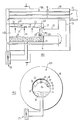
- a shell boiler is illustrated and comprises a shell 10 within which the water/steam space 10a of the boiler is contained, together with a furnace box 11 from which a discharge duct 12 for products of combustion extends to a first smoke box 13.
- a first pass of smoke tubes 14 extend from the smoke box 13 to a further smoke box.15 at the front of the furnace from which a second pass of smoke tubes 16 extend to an exit duct 17 connected to a conventional flue system.
- the furnace box 11 is divided into two compartments, namely an upper compartment 18 and a lower compartment 19.
- the two compartments are separated by a foraminous element 20 and the upper compartment 18 is connected by a downwardly extending duct 21 with the discharge duct 12 and it will be seen that the lower compartment 19 is isolated from the duct 12 except by communication through the upper compartment 18 through the foraminous element 20.
- the duct 21 is bounded at one side by a stainless steel plate 21a connected at its upper end to the foraminous element 20 and having its lower end embedded in a bed 21b of sand received in a trough 21c at the entrance to the duct 12.
- This arrangement accommodates movement of the lower end of the plate 21a relative to the wall of the duct 12 due to thermal movement of the plate 21a and of the foraminous element 20.
- the foraminous element 20 is of generally circular configuration in cross-section and is made from a plurality of members 22 which overlap both longitudinally and transversely.
- four generally part circular foraminous members are provided in the form of stainless steel plates provided with holes approximately two millimetres in diameter and there being more holes per unit area adjacent the front of the furnace box than adjacent the duct 21.
- the plates 22 are supported on struts 23 welded to the upper part lla of the peripheral wall llb of the furnace box 11 and provided with suitable support means for the plates. It will be seen that the plates 21 have out-turned flanges 24 at their lower ends for engagement with the lower struts 22.
- Means, illustrated schematically at 25 are provided to establish, in use, a fluidised bed 26 within the furnace box 11.
- products of combustion are constrained to rise vertically from the bed 26 at reduced velocity than would be the case in the absence of the foraminous element 20 and consequently carryover of fluidised material from the bed into the smoke box 13 is eliminated or reduced compared with the amount of carryover which would occur in the absence of the foraminous element 2 0 . Furthermore, because the products of combustion are constrained to rise vertically, and because a greater number of apertures per unit area are provided at the front of the furnace, any tendency for migration of the fluidised bed material towards the rear of the furnace is avoided.
- the plates 22 are supported from the wall of the furnace box 11, which is water cooled, by struts 23 the plates themselves are likewise water cooled by conduction through the struts 23.
- the furnace can be fired with any desired fuel, natural gas, oil or solid fuel.
Landscapes
- Engineering & Computer Science (AREA)
- Chemical & Material Sciences (AREA)
- Combustion & Propulsion (AREA)
- Mechanical Engineering (AREA)
- General Engineering & Computer Science (AREA)
- Physics & Mathematics (AREA)
- Thermal Sciences (AREA)
- Fluidized-Bed Combustion And Resonant Combustion (AREA)
- Solid-Fuel Combustion (AREA)
Applications Claiming Priority (2)
| Application Number | Priority Date | Filing Date | Title |
|---|---|---|---|
| GB8018999 | 1980-06-10 | ||
| GB8018999 | 1980-06-10 |
Publications (3)
| Publication Number | Publication Date |
|---|---|
| EP0044132A2 true EP0044132A2 (de) | 1982-01-20 |
| EP0044132A3 EP0044132A3 (en) | 1982-05-05 |
| EP0044132B1 EP0044132B1 (de) | 1983-12-21 |
Family
ID=10513948
Family Applications (1)
| Application Number | Title | Priority Date | Filing Date |
|---|---|---|---|
| EP81302543A Expired EP0044132B1 (de) | 1980-06-10 | 1981-06-09 | Kessel mit einer Feuerbüchse |
Country Status (6)
| Country | Link |
|---|---|
| US (1) | US4408566A (de) |
| EP (1) | EP0044132B1 (de) |
| DE (1) | DE3161692D1 (de) |
| DK (1) | DK150228C (de) |
| ES (1) | ES502877A0 (de) |
| NZ (1) | NZ197338A (de) |
Cited By (1)
| Publication number | Priority date | Publication date | Assignee | Title |
|---|---|---|---|---|
| DE19804267A1 (de) * | 1998-02-04 | 1999-08-05 | Loos Gmbh Eisenwerk Theodor | Großwasserraumkessel für Porenbrenner |
Families Citing this family (3)
| Publication number | Priority date | Publication date | Assignee | Title |
|---|---|---|---|---|
| FR2591722B1 (fr) * | 1985-12-18 | 1988-02-19 | Charbonnages De France | Generateur thermique a lit fluidise a moyens ameliores d'evacuation des cendres et de recuperation de chaleur |
| DE102015003995A1 (de) * | 2015-03-30 | 2016-10-06 | Martin GmbH für Umwelt- und Energietechnik | Verfahren zur Verbrennungsführung bei Rostfeuerungen sowie Rostfeuerung |
| ES2908378B2 (es) * | 2020-10-28 | 2022-09-09 | Cordon Urbiola Jose Luis | Caldera de combustion |
Family Cites Families (7)
| Publication number | Priority date | Publication date | Assignee | Title |
|---|---|---|---|---|
| US3442232A (en) * | 1967-11-09 | 1969-05-06 | John H White | Effluent cleaner for waste burner |
| GB1461411A (en) * | 1973-05-16 | 1977-01-13 | Energy Equip | Boilers |
| US4285282A (en) * | 1977-12-22 | 1981-08-25 | Russell E. Stadt | Rubbish and refuse incinerator |
| GB1604999A (en) * | 1978-05-31 | 1981-12-16 | Deborah Fluidised Combustion | Boilers |
| GB1604998A (en) * | 1978-05-31 | 1981-12-16 | Deborah Fluidised Combustion | Disposal of waste products by combustion |
| FR2453667A1 (fr) * | 1979-04-10 | 1980-11-07 | Bourguignonne Mec Smb | Filtre pour le depoussierage d'un fluide gazeux |
| US4338887A (en) * | 1979-09-27 | 1982-07-13 | Dorr-Oliver Incorporated | Low profile fluid bed heater or vaporizer |
-
1981
- 1981-06-08 NZ NZ197338A patent/NZ197338A/en unknown
- 1981-06-09 DE DE8181302543T patent/DE3161692D1/de not_active Expired
- 1981-06-09 US US06/272,034 patent/US4408566A/en not_active Expired - Fee Related
- 1981-06-09 ES ES502877A patent/ES502877A0/es active Granted
- 1981-06-09 EP EP81302543A patent/EP0044132B1/de not_active Expired
- 1981-06-10 DK DK252381A patent/DK150228C/da not_active IP Right Cessation
Cited By (2)
| Publication number | Priority date | Publication date | Assignee | Title |
|---|---|---|---|---|
| DE19804267A1 (de) * | 1998-02-04 | 1999-08-05 | Loos Gmbh Eisenwerk Theodor | Großwasserraumkessel für Porenbrenner |
| DE19804267C2 (de) * | 1998-02-04 | 2000-06-15 | Loos Deutschland Gmbh | Großwasserraumkessel für Porenbrenner |
Also Published As
| Publication number | Publication date |
|---|---|
| ES8204123A1 (es) | 1982-04-01 |
| EP0044132A3 (en) | 1982-05-05 |
| DK252381A (da) | 1981-12-11 |
| DK150228B (da) | 1987-01-12 |
| NZ197338A (en) | 1985-03-20 |
| US4408566A (en) | 1983-10-11 |
| DE3161692D1 (en) | 1984-01-26 |
| ES502877A0 (es) | 1982-04-01 |
| EP0044132B1 (de) | 1983-12-21 |
| DK150228C (da) | 1988-01-11 |
Similar Documents
| Publication | Publication Date | Title |
|---|---|---|
| US6532905B2 (en) | CFB with controllable in-bed heat exchanger | |
| US4253425A (en) | Internal dust recirculation system for a fluidized bed heat exchanger | |
| US4761131A (en) | Fluidized bed flyash reinjection system | |
| US4389978A (en) | Grates | |
| US5203284A (en) | Fluidized bed combustion system utilizing improved connection between the reactor and separator | |
| US4510892A (en) | Seal for boiler water wall | |
| EP0044132B1 (de) | Kessel mit einer Feuerbüchse | |
| EP0497528B1 (de) | System zur Dampferzeugung mit separatem Umlauf zwischen Feuersektion und Abscheidersektion | |
| US3908603A (en) | Boiler and elements therefor | |
| US4250839A (en) | Vapor generator utilizing stacked fluidized bed and a water-cooled heat recovery enclosure | |
| US5269262A (en) | Combustion unit | |
| GB2077616A (en) | Fluidised bed boiler | |
| US4154197A (en) | Packaged fluidized bed steam generator | |
| US3012548A (en) | Boiler | |
| US2333644A (en) | Vapor generator | |
| US1930688A (en) | Boiler | |
| US4497281A (en) | Heater | |
| US1809270A (en) | Steam generator | |
| US2840048A (en) | Grate organization | |
| CA1144827A (en) | Vapor generator utilizing stacked fluidized bed and a water-cooled heat recovery enclosure | |
| US2905154A (en) | Vapour generating and vapour heating unit | |
| US3638620A (en) | Steam or hot-water boiler | |
| US3070076A (en) | Heating boiler | |
| US1999985A (en) | Steam boiler | |
| US2818048A (en) | Boiler construction |
Legal Events
| Date | Code | Title | Description |
|---|---|---|---|
| PUAI | Public reference made under article 153(3) epc to a published international application that has entered the european phase |
Free format text: ORIGINAL CODE: 0009012 |
|
| AK | Designated contracting states |
Designated state(s): BE DE FR |
|
| PUAL | Search report despatched |
Free format text: ORIGINAL CODE: 0009013 |
|
| AK | Designated contracting states |
Designated state(s): BE DE FR |
|
| 17P | Request for examination filed |
Effective date: 19820326 |
|
| RAP1 | Party data changed (applicant data changed or rights of an application transferred) |
Owner name: THORN EMI ENERGY DEVELOPMENTS LIMITED |
|
| GRAA | (expected) grant |
Free format text: ORIGINAL CODE: 0009210 |
|
| AK | Designated contracting states |
Designated state(s): BE DE FR |
|
| REF | Corresponds to: |
Ref document number: 3161692 Country of ref document: DE Date of ref document: 19840126 |
|
| ET | Fr: translation filed | ||
| PGFP | Annual fee paid to national office [announced via postgrant information from national office to epo] |
Ref country code: DE Payment date: 19840723 Year of fee payment: 4 |
|
| PLBE | No opposition filed within time limit |
Free format text: ORIGINAL CODE: 0009261 |
|
| STAA | Information on the status of an ep patent application or granted ep patent |
Free format text: STATUS: NO OPPOSITION FILED WITHIN TIME LIMIT |
|
| 26N | No opposition filed | ||
| BECH | Be: change of holder |
Free format text: 841217 *GWB ENERGY DEVELOPMENTS LTD ET COAL INDUSTRY (PATENTS) LTD |
|
| REG | Reference to a national code |
Ref country code: FR Ref legal event code: TP |
|
| PG25 | Lapsed in a contracting state [announced via postgrant information from national office to epo] |
Ref country code: DE Effective date: 19880301 |
|
| PGFP | Annual fee paid to national office [announced via postgrant information from national office to epo] |
Ref country code: FR Payment date: 19900613 Year of fee payment: 10 |
|
| PGFP | Annual fee paid to national office [announced via postgrant information from national office to epo] |
Ref country code: BE Payment date: 19900709 Year of fee payment: 10 |
|
| PG25 | Lapsed in a contracting state [announced via postgrant information from national office to epo] |
Ref country code: BE Effective date: 19910630 |
|
| BERE | Be: lapsed |
Owner name: GWB ENERGY DEVELOPMENTS LTD ET COAL INDUSTRY (PAT Effective date: 19910630 |
|
| PG25 | Lapsed in a contracting state [announced via postgrant information from national office to epo] |
Ref country code: FR Effective date: 19920228 |
|
| REG | Reference to a national code |
Ref country code: FR Ref legal event code: ST |