EP0044189A1 - Tiroirs et montages de tiroirs - Google Patents
Tiroirs et montages de tiroirs Download PDFInfo
- Publication number
- EP0044189A1 EP0044189A1 EP81303089A EP81303089A EP0044189A1 EP 0044189 A1 EP0044189 A1 EP 0044189A1 EP 81303089 A EP81303089 A EP 81303089A EP 81303089 A EP81303089 A EP 81303089A EP 0044189 A1 EP0044189 A1 EP 0044189A1
- Authority
- EP
- European Patent Office
- Prior art keywords
- drawer
- runner
- tracks
- insert
- track
- Prior art date
- Legal status (The legal status is an assumption and is not a legal conclusion. Google has not performed a legal analysis and makes no representation as to the accuracy of the status listed.)
- Granted
Links
Images


Classifications
-
- A—HUMAN NECESSITIES
- A47—FURNITURE; DOMESTIC ARTICLES OR APPLIANCES; COFFEE MILLS; SPICE MILLS; SUCTION CLEANERS IN GENERAL
- A47B—TABLES; DESKS; OFFICE FURNITURE; CABINETS; DRAWERS; GENERAL DETAILS OF FURNITURE
- A47B88/00—Drawers for tables, cabinets or like furniture; Guides for drawers
- A47B88/40—Sliding drawers; Slides or guides therefor
- A47B88/483—Sliding drawers; Slides or guides therefor with single extensible guides or parts
- A47B88/487—Sliding drawers; Slides or guides therefor with single extensible guides or parts with rollers, ball bearings, wheels, or the like
-
- A—HUMAN NECESSITIES
- A47—FURNITURE; DOMESTIC ARTICLES OR APPLIANCES; COFFEE MILLS; SPICE MILLS; SUCTION CLEANERS IN GENERAL
- A47B—TABLES; DESKS; OFFICE FURNITURE; CABINETS; DRAWERS; GENERAL DETAILS OF FURNITURE
- A47B88/00—Drawers for tables, cabinets or like furniture; Guides for drawers
- A47B88/40—Sliding drawers; Slides or guides therefor
- A47B88/402—Profiles or supporting structures for supporting single drawers
-
- A—HUMAN NECESSITIES
- A47—FURNITURE; DOMESTIC ARTICLES OR APPLIANCES; COFFEE MILLS; SPICE MILLS; SUCTION CLEANERS IN GENERAL
- A47B—TABLES; DESKS; OFFICE FURNITURE; CABINETS; DRAWERS; GENERAL DETAILS OF FURNITURE
- A47B88/00—Drawers for tables, cabinets or like furniture; Guides for drawers
- A47B88/40—Sliding drawers; Slides or guides therefor
- A47B88/453—Actuated drawers
- A47B88/46—Actuated drawers operated by mechanically-stored energy, e.g. by springs
- A47B88/467—Actuated drawers operated by mechanically-stored energy, e.g. by springs self-closing
-
- A—HUMAN NECESSITIES
- A47—FURNITURE; DOMESTIC ARTICLES OR APPLIANCES; COFFEE MILLS; SPICE MILLS; SUCTION CLEANERS IN GENERAL
- A47B—TABLES; DESKS; OFFICE FURNITURE; CABINETS; DRAWERS; GENERAL DETAILS OF FURNITURE
- A47B2210/00—General construction of drawers, guides and guide devices
- A47B2210/0002—Guide construction for drawers
- A47B2210/0029—Guide bearing means
- A47B2210/0043—Wheels
-
- A—HUMAN NECESSITIES
- A47—FURNITURE; DOMESTIC ARTICLES OR APPLIANCES; COFFEE MILLS; SPICE MILLS; SUCTION CLEANERS IN GENERAL
- A47B—TABLES; DESKS; OFFICE FURNITURE; CABINETS; DRAWERS; GENERAL DETAILS OF FURNITURE
- A47B2210/00—General construction of drawers, guides and guide devices
- A47B2210/0002—Guide construction for drawers
- A47B2210/0051—Guide position
- A47B2210/0059—Guide located at the side of the drawer
Definitions
- This invention relates to drawers and especially to drawers of the kind which are adapted to be slidably mounted on a pair of runners fixed to a cabinet or like support structure by means of intermediate roller assemblies or carriages which are movable relative to the drawer and the associated runners during opening and closing movements of the drawer.
- Drawers of this kind have a smooth opening and closing action but suffer from certain disadvantages.
- the drawer tends to rock or tilt about the roller assembly at certain positions during opening and closing and this can cause mal-functioning of the roller assembly, particularly if the drawer is heavily laden at the rear or if the user tends to lift the front of the drawer during opening and closing movements.
- the invention provides a drawer having longitudinally extending tracks in its opposite sides, each of which is adapted to co-operate with a drawer runner mounted in a cabinet in which the drawer is supported in use, each of said tracks incorporating means to stabilise the drawer against rocking or tilting movement during opening and closing.
- said means to stabilise the drawer comprises formations formed within the respective drawer tracks and operative to engage with the associated runners to prevent lifting movement of the front of the drawer until it has : been withdrawn framthe cabinet to a predetermined extent.
- Each formation may comprise a shelf raised from the base of the associated track and extending rearwardly from the forward end thereof, the shelf being adapted to engage beneath the associated runner and prevent upward movement of the track and hence the drawer relative to the runner during initial opening and final closing movement of the drawer.
- each formation may comprise a projection on or adjacent the base of the associated track towards the forward end thereof.
- the tracks in the drawer sides may be formed integrally with the sides of the drawer but are preferably formed as separate components engaged and retained in recesses in the drawer sides.
- the drawer sides are preferably of hollow section and formed by extrusion from synthetic plastics material, the inserts also being formed from plastics material by a moulding process.
- the tracks may be provided with additional formations serving as stops, self closing devices and the like.
- the drawer sides preferably incorporate longitudinal slots in the faces thereof opposite to those in which said recesses are formed, the slots receiving the edges of the drawer bottom.
- the drawer sides are connected to the front and back walls of the drawer by means of connecting pieces having projecting spigots which engage in the hollow ends of the side walls and are suitably retained therein.
- connecting pieces having projecting spigots which engage in the hollow ends of the side walls and are suitably retained therein.
- the spigots may be retained by means of detents projecting therefrom and engaging in holes formed adjacent the ends of the side walls.
- the invention also provides a drawer runner insert comprising an elongated member adapted to be engaged and retained in a recess in a drawer side to form a runner track and incorporating means to stabilize the drawer against rocking or tilting movement during sliding movement of the drawer relative to an associate runner engaged in said track.
- a drawer incorporates side wall panels 5 in the form of hollow section profiles having upper and lower sections 6A and 6B interconnected" by a hollow web 7 which defines, together with the upper and lower sections, a recess 8 extending longitudinally of the panel and formed on the face thereof which is outermost in use.
- the side wall panels are assembled with other panel members to form a drawer by means of front and rear connecting pieces.
- Each front connecting piece one of which is partly visible in Fig. 3 comprises a face plate 9 adapted to be secured by screws or the like to a drawer front 10 and having rearwardly projecting spigots (not shown) each of which carries a projecting detent 11.
- the spigots are adapted to form a close push fit within the hollow end of the associated side wall panel 5 and the detents engage in holes formed adjacent the ends of the panel.
- the rear connectors one of which is partly visible at 12 in Fig.
- a longitudinal slot 13 is provided in the inwardly directed face of each panel member to receive the edge of a drawer bottom.
- the recesses 8 in the side wall panels are each adapted to receive and retain a separate insert 14 (Figs. 2 and 3) defining a runner track.
- the insert is of moulded plastics construction and of generally U-shaped cross-section so as to be received within the recess in the panel member.
- the insert comprises a back wall 15 and upper and lower walls 16A and 16B which define a track adapted in use to receive a runner assembly on which the drawer is mounted.
- the outer edges of the upper and lower walls 16A, 16B are provided with longitudinal grooves 17A and 17B respectively which engage with longitudinally extending lips 8A, 8B projecting from the upper and lower edges of the recess 8. In this way the insert may be pressed into the recess 8 or slid in from one end, the lips 8A and 8B retaining the insert against lateral withdrawal from the recess.
- the drawer is mounted on a pair of angle section runners one of which is shown at 18 in Fig. 2 and comprises a vertical flange 18A by means of which the runner may be secured to the wall of a cabinet or the like and a horizontal flange 18B which projects into the track formed by the insert 14.
- a roller assembly or carriage shown at 19 in Fig. 3 but omitted from Fig. 2 for clarity acts between the flange 18B and the upper and lower walls 16A and 16B of the insert 14 to support the drawer on the runner.
- the roller assembly also incorporates rollers (not shown) which run against the back wall 15 of the insert 14.
- the roller carriage 19 is freely movable relative to the runner and the drawer within limits defined by a stop member 20 projecting into the track defined by the insert 14 and a further stop member 21 on the runner 18.
- Other formations are also formed within the insert 14 to act upon the roller carriage to perform self-closing or other desired functions.
- the track defining insert 14 Towards its forward end the track defining insert 14 is provided with a formation in the nature of a shelf 22 (Fig. 3) which is raised from the base or lower wall 16 B and extends rearwardly for about one third of the length of the insert.
- the formation 22 is provided with a tapered portion or ramp 22A extending downwards to the floor 16B.
- the formation 22 is raised from the floor 16B by a distance such that it locates closely beneath the flange 18B of the runner 18 when the drawer is approaching its closed position. This prevents the front of the drawer from rising in this position and this in turn prevents the roller carriage 19, which is then located at the rear of the runner 18 from disengaging from or jumping off the runner and thereby causing malfunction.
- the rear end of the flange 18B of the runner carries the stop member 21 which limits rearward travel of the roller carriage 19 and if the drawer is permitted to rock or tilt the rear roller of the carriage can in some circumstances and especially if the drawer is heavily loaded at the rear, be forced past the stop member 21.
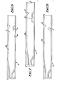
- Figs. 4 to 8 illustrate a number of alternative ways of stabilizing the drawer against rocking or tilting movement.
- a modified form of shelf 25 is provided which extends horizontally rearwards from the front end of the track defining or runner insert 14.
- the stop member 20 of the Fig. 3 arrangement is also extended forwardly to the front of the insert as shown in 26 whereby a relatively narrow track or slot 27 is defined to receive and guide the forward end of the runner.
- the upper extension 26 of Fig. 4 is retained but the shelf 25 is replaced by a projection 28 extending upwardly from the floor 16B of the insert 14 in a position corresponding to the rear end of the shelf 25.
- the projection has a rearwardly directed sloping face 28A which acts as a ramp or cam to pick up the forward end of the runner during opening of the drawer and hence prevent or reduce rocking or tilting movement in the same manner as the shelf.
- Fig. 6 shows a modification of the arrangement shown in Fig. 5 in which the projection 29 is carried by the back wall 15 of the insert and is spaced from the floor 16B but is otherwise similarly positioned and operates in a similar fashion.
- Fig. 7 shows an alternative form of projection or ramp 30 mounted on the floor of the insert and spaced from the forward end and Fig. 8 shows the use of a stud or pin 31 in place of the projections or formations 28, 29 and 30 of Figs. 5 to 7.
- the upper wall 16A of the track is similar to that of Fig. 3 but :, could correspond to that of Figs. 4 and 5 if desired.
Landscapes
- Engineering & Computer Science (AREA)
- Mechanical Engineering (AREA)
- Drawers Of Furniture (AREA)
- Vehicle Step Arrangements And Article Storage (AREA)
- Medicines That Contain Protein Lipid Enzymes And Other Medicines (AREA)
- Steroid Compounds (AREA)
- Laser Surgery Devices (AREA)
- Cold Air Circulating Systems And Constructional Details In Refrigerators (AREA)
- Valve Device For Special Equipments (AREA)
Priority Applications (1)
| Application Number | Priority Date | Filing Date | Title |
|---|---|---|---|
| AT81303089T ATE34289T1 (de) | 1980-07-11 | 1981-07-07 | Schubladen und schubladenzusammensetzung. |
Applications Claiming Priority (2)
| Application Number | Priority Date | Filing Date | Title |
|---|---|---|---|
| GB8022770 | 1980-07-11 | ||
| GB8022770 | 1980-07-11 |
Publications (2)
| Publication Number | Publication Date |
|---|---|
| EP0044189A1 true EP0044189A1 (fr) | 1982-01-20 |
| EP0044189B1 EP0044189B1 (fr) | 1988-05-18 |
Family
ID=10514706
Family Applications (1)
| Application Number | Title | Priority Date | Filing Date |
|---|---|---|---|
| EP81303089A Expired EP0044189B1 (fr) | 1980-07-11 | 1981-07-07 | Tiroirs et montages de tiroirs |
Country Status (9)
| Country | Link |
|---|---|
| US (1) | US4458964A (fr) |
| EP (1) | EP0044189B1 (fr) |
| AT (1) | ATE34289T1 (fr) |
| AU (1) | AU549217B2 (fr) |
| CA (1) | CA1169908A (fr) |
| DE (1) | DE3176742D1 (fr) |
| FI (1) | FI812130A7 (fr) |
| GB (1) | GB2079585B (fr) |
| NZ (1) | NZ197679A (fr) |
Cited By (1)
| Publication number | Priority date | Publication date | Assignee | Title |
|---|---|---|---|---|
| AT386945B (de) * | 1982-02-17 | 1988-11-10 | Blum Gmbh Julius | Ausziehfuehrungsgarnitur fuer schubladen, insbesondere fuer plastikschubladen |
Families Citing this family (15)
| Publication number | Priority date | Publication date | Assignee | Title |
|---|---|---|---|---|
| AU5941990A (en) * | 1989-06-30 | 1991-01-17 | Poqet Computer Corporation | Memory card tray for portable computer |
| DE9413108U1 (de) * | 1994-08-17 | 1995-01-12 | Grass AG, Höchst, Vorarlberg | Schubladenführung |
| US6217139B1 (en) * | 1997-09-09 | 2001-04-17 | Kimball International, Inc. | Drawer for standardized furniture unit |
| US6142596A (en) * | 1998-08-20 | 2000-11-07 | Knape & Vogt Manufacturing, Co. | Under mount drawer slide |
| US6379045B1 (en) | 2000-03-17 | 2002-04-30 | Jonathan Manufacturing Corporation | Quick disconnect slide assembly |
| AT6364U1 (de) * | 2002-08-29 | 2003-09-25 | Blum Gmbh Julius | Ausziehführungsgarnitur für schubladen |
| US20070227409A1 (en) * | 2006-03-29 | 2007-10-04 | Ching-Shan Chu | UPS uninterruptible power supply mobile computer table structure |
| DE102007005948A1 (de) * | 2007-02-06 | 2008-08-07 | BSH Bosch und Siemens Hausgeräte GmbH | Kältegerät mit Teleskopauszug |
| US8348361B2 (en) * | 2008-06-30 | 2013-01-08 | Electrolux Home Products, Inc. | Additive dispenser drawer assembly |
| US8430567B2 (en) * | 2010-08-26 | 2013-04-30 | Knape & Vogt Manufacturing Company | Load adaptive roller carriage assembly |
| DE202013011426U1 (de) * | 2013-12-20 | 2015-03-23 | Grass Gmbh | Schubladenwandeelement |
| KR102373219B1 (ko) | 2015-12-10 | 2022-03-17 | 삼성전자주식회사 | 냉장고 |
| CN109691796A (zh) * | 2017-10-20 | 2019-04-30 | 五冶集团上海有限公司 | 一种可移动的可拆卸式零号图纸架 |
| US11304527B1 (en) * | 2019-12-06 | 2022-04-19 | Dooli Products, LLC | Drawer retention mechanisms for furniture |
| KR20240031808A (ko) * | 2022-09-01 | 2024-03-08 | 엘지전자 주식회사 | 냉장고 |
Citations (3)
| Publication number | Priority date | Publication date | Assignee | Title |
|---|---|---|---|---|
| FR1451147A (fr) * | 1964-11-12 | 1966-06-24 | Desoer Sa | Dispositif d'amortissement et de stabilisation de la fin de course d'un tiroir |
| CH588236A5 (en) * | 1974-12-09 | 1977-05-31 | Kuenzler Ernst Ag | Drawer parallel guide mechanism - has two stabilizing plates with pivotal mounting and linkages |
| FR2358129A1 (fr) * | 1976-07-14 | 1978-02-10 | Lb Plastics Ltd | Perfectionnements aux tiroirs de meubles et aux pieces les composant |
Family Cites Families (14)
| Publication number | Priority date | Publication date | Assignee | Title |
|---|---|---|---|---|
| DE107273C (fr) * | ||||
| US747685A (en) * | 1901-07-31 | 1903-12-22 | William H Coye | Drawer. |
| US962502A (en) * | 1910-02-17 | 1910-06-28 | Axel Elmborg | Drawer-guide. |
| US1944477A (en) * | 1932-11-26 | 1934-01-23 | Jr James Tillotson | Wood furniture drawer support |
| US2859070A (en) * | 1954-05-21 | 1958-11-04 | Mc Graw Edison Co | Extension hanger for cabinet drawer |
| US2880040A (en) * | 1955-08-29 | 1959-03-31 | Mc Graw Edison Co | Drawer suspension |
| DE1554302A1 (de) * | 1965-12-21 | 1970-08-20 | Krause Kg Robert | Fuehrung,insbesondere fuer Schubladen od.dgl. |
| GB1190650A (en) * | 1967-11-08 | 1970-05-06 | Leslie William Llwellyn Alston | Improvements in or relating to Drawers for Furniture. |
| CH607681A5 (fr) * | 1975-02-25 | 1978-10-13 | Blum Gmbh Julius | |
| US3954315A (en) * | 1975-02-26 | 1976-05-04 | Sanden Edwin H | Cabinet drawer |
| US4162114A (en) * | 1977-04-26 | 1979-07-24 | L. B. (Plastics) Limited | Drawers and drawer components |
| AT351198B (de) * | 1977-05-13 | 1979-07-10 | Blum Gmbh Julius | Schubladenfuehrung |
| AT356315B (de) * | 1977-11-17 | 1980-04-25 | Blum Gmbh Julius | Ausziehfuehrung fuer schubladen od.dgl. |
| US4272139A (en) * | 1978-09-12 | 1981-06-09 | Jacmorr Manufacturing Limited | Sliding drawer suspension |
-
1981
- 1981-07-06 FI FI812130A patent/FI812130A7/fi not_active Application Discontinuation
- 1981-07-06 US US06/280,196 patent/US4458964A/en not_active Expired - Fee Related
- 1981-07-07 DE DE8181303089T patent/DE3176742D1/de not_active Expired
- 1981-07-07 AT AT81303089T patent/ATE34289T1/de not_active IP Right Cessation
- 1981-07-07 EP EP81303089A patent/EP0044189B1/fr not_active Expired
- 1981-07-07 GB GB8120942A patent/GB2079585B/en not_active Expired
- 1981-07-09 AU AU72721/81A patent/AU549217B2/en not_active Ceased
- 1981-07-10 NZ NZ197679A patent/NZ197679A/en unknown
- 1981-07-10 CA CA000381498A patent/CA1169908A/fr not_active Expired
Patent Citations (3)
| Publication number | Priority date | Publication date | Assignee | Title |
|---|---|---|---|---|
| FR1451147A (fr) * | 1964-11-12 | 1966-06-24 | Desoer Sa | Dispositif d'amortissement et de stabilisation de la fin de course d'un tiroir |
| CH588236A5 (en) * | 1974-12-09 | 1977-05-31 | Kuenzler Ernst Ag | Drawer parallel guide mechanism - has two stabilizing plates with pivotal mounting and linkages |
| FR2358129A1 (fr) * | 1976-07-14 | 1978-02-10 | Lb Plastics Ltd | Perfectionnements aux tiroirs de meubles et aux pieces les composant |
Cited By (1)
| Publication number | Priority date | Publication date | Assignee | Title |
|---|---|---|---|---|
| AT386945B (de) * | 1982-02-17 | 1988-11-10 | Blum Gmbh Julius | Ausziehfuehrungsgarnitur fuer schubladen, insbesondere fuer plastikschubladen |
Also Published As
| Publication number | Publication date |
|---|---|
| NZ197679A (en) | 1984-12-14 |
| CA1169908A (fr) | 1984-06-26 |
| AU7272181A (en) | 1982-01-14 |
| ATE34289T1 (de) | 1988-06-15 |
| AU549217B2 (en) | 1986-01-23 |
| FI812130L (fi) | 1982-01-12 |
| GB2079585B (en) | 1985-02-13 |
| EP0044189B1 (fr) | 1988-05-18 |
| DE3176742D1 (en) | 1988-06-23 |
| GB2079585A (en) | 1982-01-27 |
| FI812130A7 (fi) | 1982-01-12 |
| US4458964A (en) | 1984-07-10 |
Similar Documents
| Publication | Publication Date | Title |
|---|---|---|
| US4458964A (en) | Drawers and drawer assemblies | |
| US4298234A (en) | Drawers and drawer components | |
| US3752553A (en) | Drawer with snap-on front panel | |
| US4370007A (en) | Sliding drawer suspension | |
| US3701577A (en) | Drawer slide assembly | |
| US4067632A (en) | Drawer slide | |
| US4272139A (en) | Sliding drawer suspension | |
| US5664855A (en) | Fitting for the adjustable-height mounting of drawers | |
| US4955160A (en) | Guide wall assembly for drawers | |
| US5536083A (en) | Pull-out guide assembly for drawers | |
| US4564248A (en) | Pull-out guide for drawers | |
| US4427245A (en) | Drawer panel with track insert | |
| CA2280376A1 (fr) | Coulisse de tiroir a montage par la face inferieure | |
| HK55883A (en) | Improvements in and relating to drawers and drawer components | |
| EP0289256A1 (fr) | Tiroirs et éléments de tiroirs | |
| US6481812B1 (en) | Undermount drawer guide assembly | |
| US4639145A (en) | Drawer guide | |
| US4438994A (en) | Drawers and drawer runners | |
| US4212503A (en) | Drawers and drawer runners | |
| US4892368A (en) | Drawer slide | |
| US4186979A (en) | Drawers | |
| US5131733A (en) | Mounting bracket for drawer guides | |
| US4508394A (en) | Drawer guide assembly | |
| US4749243A (en) | Drawer with improved pull-out rail, drawer frame and rail slide | |
| US4895417A (en) | Drawer side wall |
Legal Events
| Date | Code | Title | Description |
|---|---|---|---|
| PUAI | Public reference made under article 153(3) epc to a published international application that has entered the european phase |
Free format text: ORIGINAL CODE: 0009012 |
|
| AK | Designated contracting states |
Designated state(s): AT DE FR SE |
|
| 17P | Request for examination filed |
Effective date: 19820719 |
|
| GRAA | (expected) grant |
Free format text: ORIGINAL CODE: 0009210 |
|
| AK | Designated contracting states |
Kind code of ref document: B1 Designated state(s): AT DE FR SE |
|
| PG25 | Lapsed in a contracting state [announced via postgrant information from national office to epo] |
Ref country code: AT Effective date: 19880518 |
|
| REF | Corresponds to: |
Ref document number: 34289 Country of ref document: AT Date of ref document: 19880615 Kind code of ref document: T |
|
| REF | Corresponds to: |
Ref document number: 3176742 Country of ref document: DE Date of ref document: 19880623 |
|
| ET | Fr: translation filed | ||
| PLBE | No opposition filed within time limit |
Free format text: ORIGINAL CODE: 0009261 |
|
| STAA | Information on the status of an ep patent application or granted ep patent |
Free format text: STATUS: NO OPPOSITION FILED WITHIN TIME LIMIT |
|
| 26N | No opposition filed | ||
| PGFP | Annual fee paid to national office [announced via postgrant information from national office to epo] |
Ref country code: FR Payment date: 19900531 Year of fee payment: 10 |
|
| PGFP | Annual fee paid to national office [announced via postgrant information from national office to epo] |
Ref country code: DE Payment date: 19900621 Year of fee payment: 10 |
|
| PG25 | Lapsed in a contracting state [announced via postgrant information from national office to epo] |
Ref country code: FR Effective date: 19920331 |
|
| PG25 | Lapsed in a contracting state [announced via postgrant information from national office to epo] |
Ref country code: DE Effective date: 19920401 |
|
| REG | Reference to a national code |
Ref country code: FR Ref legal event code: ST |
|
| PGFP | Annual fee paid to national office [announced via postgrant information from national office to epo] |
Ref country code: SE Payment date: 19940731 Year of fee payment: 14 |
|
| EAL | Se: european patent in force in sweden |
Ref document number: 81303089.7 |
|
| PG25 | Lapsed in a contracting state [announced via postgrant information from national office to epo] |
Ref country code: SE Effective date: 19950708 |
|
| EUG | Se: european patent has lapsed |
Ref document number: 81303089.7 |