EP0044263B1 - Durchfluss-Strom-Umwandler mit schneller Reaktion, insbesondere zum Steuern von Betätigungs- oder Verteilvorrichtungen - Google Patents
Durchfluss-Strom-Umwandler mit schneller Reaktion, insbesondere zum Steuern von Betätigungs- oder Verteilvorrichtungen Download PDFInfo
- Publication number
- EP0044263B1 EP0044263B1 EP81440017A EP81440017A EP0044263B1 EP 0044263 B1 EP0044263 B1 EP 0044263B1 EP 81440017 A EP81440017 A EP 81440017A EP 81440017 A EP81440017 A EP 81440017A EP 0044263 B1 EP0044263 B1 EP 0044263B1
- Authority
- EP
- European Patent Office
- Prior art keywords
- electro
- valves
- flow
- comparator
- valve
- Prior art date
- Legal status (The legal status is an assumption and is not a legal conclusion. Google has not performed a legal analysis and makes no representation as to the accuracy of the status listed.)
- Expired
Links
- 239000012530 fluid Substances 0.000 claims abstract description 12
- 230000010349 pulsation Effects 0.000 claims description 6
- 238000006243 chemical reaction Methods 0.000 claims description 4
- 230000010363 phase shift Effects 0.000 description 7
- 230000000694 effects Effects 0.000 description 5
- 238000004804 winding Methods 0.000 description 5
- XEEYBQQBJWHFJM-UHFFFAOYSA-N Iron Chemical compound [Fe] XEEYBQQBJWHFJM-UHFFFAOYSA-N 0.000 description 4
- 239000007788 liquid Substances 0.000 description 4
- 230000007423 decrease Effects 0.000 description 2
- 238000010586 diagram Methods 0.000 description 2
- 239000000446 fuel Substances 0.000 description 2
- 229910052742 iron Inorganic materials 0.000 description 2
- 125000004122 cyclic group Chemical group 0.000 description 1
- 238000006073 displacement reaction Methods 0.000 description 1
- 238000005516 engineering process Methods 0.000 description 1
- 235000021183 entrée Nutrition 0.000 description 1
- 239000007789 gas Substances 0.000 description 1
- 238000002347 injection Methods 0.000 description 1
- 239000007924 injection Substances 0.000 description 1
- 239000000203 mixture Substances 0.000 description 1
- 230000003071 parasitic effect Effects 0.000 description 1
- 238000005086 pumping Methods 0.000 description 1
- 238000010926 purge Methods 0.000 description 1
- 230000000630 rising effect Effects 0.000 description 1
- 239000000243 solution Substances 0.000 description 1
- 230000001052 transient effect Effects 0.000 description 1
- 230000003313 weakening effect Effects 0.000 description 1
Images

Classifications
-
- F—MECHANICAL ENGINEERING; LIGHTING; HEATING; WEAPONS; BLASTING
- F15—FLUID-PRESSURE ACTUATORS; HYDRAULICS OR PNEUMATICS IN GENERAL
- F15B—SYSTEMS ACTING BY MEANS OF FLUIDS IN GENERAL; FLUID-PRESSURE ACTUATORS, e.g. SERVOMOTORS; DETAILS OF FLUID-PRESSURE SYSTEMS, NOT OTHERWISE PROVIDED FOR
- F15B9/00—Servomotors with follow-up action, e.g. obtained by feed-back control, i.e. in which the position of the actuated member conforms with that of the controlling member
- F15B9/02—Servomotors with follow-up action, e.g. obtained by feed-back control, i.e. in which the position of the actuated member conforms with that of the controlling member with servomotors of the reciprocatable or oscillatable type
- F15B9/03—Servomotors with follow-up action, e.g. obtained by feed-back control, i.e. in which the position of the actuated member conforms with that of the controlling member with servomotors of the reciprocatable or oscillatable type with electrical control means
-
- G—PHYSICS
- G05—CONTROLLING; REGULATING
- G05D—SYSTEMS FOR CONTROLLING OR REGULATING NON-ELECTRIC VARIABLES
- G05D3/00—Control of position or direction
- G05D3/12—Control of position or direction using feedback
- G05D3/14—Control of position or direction using feedback using an analogue comparing device
- G05D3/18—Control of position or direction using feedback using an analogue comparing device delivering a series of pulses
Definitions
- the present invention relates to the field of servo-control of devices for operating loads, or the like, or of distribution devices, and has for its object a current-flow converter with fast response intended for this purpose.
- solenoid valves which are logic distributors.
- several solenoid valves having different flow rates, therefore different passage diameters are grouped into a distribution group allowing the obtaining of several flow rates varying with the solenoid valve (s) used.
- the number of possible operating speeds is a direct function of the number of solenoid valves used, so that for a relatively fine conversion of the flow rates, and therefore of the speeds, the distribution group becomes relatively large, each solenoid valve being generally followed by an adjustable choke.
- US-A-4,015,426 describes a device for controlling the flow of liquid with low viscosity such as fuel.
- a regular flow at the nozzle can not be obtained, notable and inevitable pulsations occurring due to the incompressibility of liquids.
- the solenoid valve used in this device therefore operates at a relatively low switching frequency, the pulsations being of no appreciable effect on the desired effect in the case of an injection of liquid fuel, namely obtaining a temperature or d 'a power.
- the present invention aims to overcome these drawbacks.
- a rapid response current-flow converter for metering a flow of fluid, in particular gaseous, towards a receiving member, in particular a device for operating loads, such as a jack or a distribution device; said converter being constituted by several solenoid valves each controlled by an electronic control member and connected by their inlet orifice to a reservoir for pressurized fluid and by outlet orifice to the receiving member; and by a member, measuring a parameter which is proportional to the flow rate, in particular a position sensor mechanically connected to the operating device or a flow meter; the output of the sensor member is connected to an input of a comparator, the other input of which is connected to a setpoint signal-giving member, this comparator providing a voltage, which is a direct function of the difference between setpoint and actual value; said converter further comprises a sawtooth generator connected to a threshold detector which is connected to the output of the comparator, and which compares the signal from the sawtooth generator with that from the comparator and provides a slot signal to duty
- the rapid response current-flow converter for metering a flow of fluid, in particular gaseous, towards a receiving member 6, in particular a device for operating loads, such as a jack or a distribution device, and which is essentially constituted by solenoid valves 1 and 2 each controlled by an electronic control member 3 and 4, and connected by their inlet orifice to a pressurized fluid reservoir 5, such as a compressed air reservoir, and through one of their outlet orifices to the receiving member 6; and by a sensor member 7 measuring a parameter which is proportional to the flow rate, in particular a position sensor mechanically connected to the operating device or a flow meter, the output of this sensor being connected to an input of a comparator 8, the another input is connected to a setpoint signal giving member 9, this comparator 8 supplying a voltage, which is a direct function of the difference between setpoint value and actual value; said converter further comprising a sawtooth generator 10 connected to
- the solenoid valves are each devoid of a conductive ring concentric with the winding, and of a non-magnetic sealed tube phase shifting or weakening the magnetic field created by the coil.
- Each solenoid valve is further provided with a core whose mass is adjusted to allow an optimal effect, both from the point of magnetic view than inertial, and is supplied by a switching circuit which gives substantially square pulses, by means of the electronic control member 3, 4 which is assigned to it.
- the flow rate of the solenoid valves 1 and 2 can be varied by varying their duty cycle, that is to say by operating them for a determined time interval, then leaving them to stand still for another time interval.
- the latter has two possible states, namely a zero flow at rest, and a nominal flow in action.
- its average flow will be 50% and strongly pulsed, so that it will be a function of the walking factor or the form factor of the control current.
- this possible variation in the flow rate has however been accompanied by sensitive pulses from the load operating member, owing to the fact that the switching times were relatively long.
- the solenoid valves 1 and 2 make it possible to overcome this drawback of the fact that they have a high switching frequency, of the order of 100 Hz, by their winding supplied, in transient mode, via the control members.
- electronics 3 and 4 and by a switching circuit giving substantially square pulses, therefore a rapidly rising front favoring a rapid response of the core.
- the pulses of flow are notably leveled by a fast commutation of the nucleus, and the residual pulses have no effect on the served receivers.
- the winding will be more powerful than normal, and the core mass will be adjusted to allow optimal magnetic and inertial effects.
- the growth of the magnetic field must be high, a waveform with stiff fronts is essential, the square wave being perfectly suitable despite its richness in harmonics.
- the solenoid valve In order not to phase out or weaken the magnetic field created by the winding, the solenoid valve is not provided with a phase shift ring concentric with its winding, nor with a sealed magnetic tube.
- the increase in frequency results in a reduction of the flow range, which becomes so narrow that the sharp adjustment is unstable.
- a frequency close to 100 Hz is therefore optimal for operation, allowing a large flow range, close to 100%, with a low flow pulsation.
- the switching rate increases, and the insensitive vibrations which remain are annihilated due to the inertia of the jack.
- the jack and the load remain stationary. If the duty factor increases, the cylinder exits at a speed which increases with the duty factor, while if the latter decreases below 50%, the jack under load returns at a speed which increases in correspondence with the decrease in said market factor.
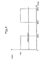
- Figure 2 shows an operating cycle of a solenoid valve. Considering that such a cycle extends over 0.02 seconds, and that in this cycle the solenoid valve works at full power for 0.01 seconds, that is to say during half of the cycle, and is at rest during the other half, the average flow rate of the solenoid valve on the cycle will be 50%, the solenoid valve will therefore have a duty factor of 50%.
- the duty cycle may vary slightly around the predetermined value.
- This duty factor is automatically adjusted from the set value from the member 9 and the position value from the sensor 7 by the comparator 8, and the operating frequency of the solenoid valves 1 and 2 is given by the generator. saw teeth 10 previously adjusted.
- the residual pulses or residual vibrations can be eliminated, in accordance with the invention, by the provision of several solenoid valves mounted in parallel, whose inputs and outputs are connected together, but whose electronic control members 3 and 4 have an offset to the power supply equal to $ 2, n representing the number of solenoid valves n used, and this offset is obtained by means of a phase shift circuit 12 equipping each additional solenoid valve, and the output of the detector 11 then delivers a slot with a duty cycle represented by point C at the input of each circuit 12 and to the control member 3 assigned to it.
- the solenoid valve (s) used are of the 3-way - 2-position type, with exhaust to the atmosphere.
- the solenoid valves used are of the 2-way - 2-position type.
- the cylinder chamber will successively receive partial filling (20%) followed by partial purging or partial emptying (80%).
- the return speed of the piston is lower than the exit speed due to the fact that the pressure of the supply fluid is twice that in the chamber of the jack.
- the invention it is possible to produce a current-flow converter with very rapid response, allowing very precise control of load handling devices, or the like, such as, in particular semi-automatic gearboxes of tractors. road, and whose valves are very simple and can be easily replaced in the event of a fault.
- the device has great operating flexibility, and a rapid variation of the duty cycle between 0 and 100% is easily achievable, in particular thanks to the solenoid valves.
- the device according to the invention is very reliable, the valves operating very well in a temperature range extending from -20 ° C + 80 ° C, and the electronic circuits, which are relatively simple, can be moved to their protection.
Landscapes
- Engineering & Computer Science (AREA)
- Physics & Mathematics (AREA)
- Automation & Control Theory (AREA)
- Mechanical Engineering (AREA)
- General Engineering & Computer Science (AREA)
- General Physics & Mathematics (AREA)
- Fluid Mechanics (AREA)
- Servomotors (AREA)
- Flow Control (AREA)
- Emergency Protection Circuit Devices (AREA)
- Electrical Discharge Machining, Electrochemical Machining, And Combined Machining (AREA)
- Magnetically Actuated Valves (AREA)
- Control Of Non-Electrical Variables (AREA)
Claims (5)
Priority Applications (1)
| Application Number | Priority Date | Filing Date | Title |
|---|---|---|---|
| AT81440017T ATE15928T1 (de) | 1980-06-10 | 1981-06-09 | Durchfluss-strom-umwandler mit schneller reaktion, insbesondere zum steuern von betaetigungs- oder verteilvorrichtungen. |
Applications Claiming Priority (2)
| Application Number | Priority Date | Filing Date | Title |
|---|---|---|---|
| FR8013347 | 1980-06-10 | ||
| FR8013347A FR2484106A1 (fr) | 1980-06-10 | 1980-06-10 | Convertisseur courant-debit a reponse rapide, notamment pour l'asservissement de dispositifs de manoeuvre de charges, ou autres, ou de dispositifs de distribution |
Publications (2)
| Publication Number | Publication Date |
|---|---|
| EP0044263A1 EP0044263A1 (de) | 1982-01-20 |
| EP0044263B1 true EP0044263B1 (de) | 1985-10-02 |
Family
ID=9243142
Family Applications (1)
| Application Number | Title | Priority Date | Filing Date |
|---|---|---|---|
| EP81440017A Expired EP0044263B1 (de) | 1980-06-10 | 1981-06-09 | Durchfluss-Strom-Umwandler mit schneller Reaktion, insbesondere zum Steuern von Betätigungs- oder Verteilvorrichtungen |
Country Status (4)
| Country | Link |
|---|---|
| EP (1) | EP0044263B1 (de) |
| AT (1) | ATE15928T1 (de) |
| DE (1) | DE3172501D1 (de) |
| FR (1) | FR2484106A1 (de) |
Families Citing this family (2)
| Publication number | Priority date | Publication date | Assignee | Title |
|---|---|---|---|---|
| USRE33846E (en) * | 1982-04-01 | 1992-03-17 | Deere & Company | Electrohydraulic valve system |
| US4437385A (en) * | 1982-04-01 | 1984-03-20 | Deere & Company | Electrohydraulic valve system |
Family Cites Families (8)
| Publication number | Priority date | Publication date | Assignee | Title |
|---|---|---|---|---|
| US3295421A (en) * | 1964-03-16 | 1967-01-03 | Loran F Mccormick | Position control circuit |
| US3279323A (en) * | 1964-09-28 | 1966-10-18 | North American Aviation Inc | Electrohydraulic actuator |
| US3521535A (en) * | 1967-11-07 | 1970-07-21 | Chandler Evans Inc | Time modulated pneumatically actuated position control mechanism |
| US3561326A (en) * | 1968-03-06 | 1971-02-09 | Parker Hannifin Corp | Pulse phase modulated servoactuator |
| US3637319A (en) * | 1969-12-08 | 1972-01-25 | Gen Electric | Method for dual mode control changeover in a steam turbine |
| US3659631A (en) * | 1970-08-05 | 1972-05-02 | Moore Business Forms Inc | Controller for a pulsed servovalve |
| DE2203036A1 (de) * | 1971-02-10 | 1972-08-17 | Elektro App Werke Berlin Inst | Stelleinrichtung |
| US4015426A (en) * | 1972-11-20 | 1977-04-05 | Nippondenso Co., Ltd. | Fuel control system |
-
1980
- 1980-06-10 FR FR8013347A patent/FR2484106A1/fr active Granted
-
1981
- 1981-06-09 DE DE8181440017T patent/DE3172501D1/de not_active Expired
- 1981-06-09 AT AT81440017T patent/ATE15928T1/de not_active IP Right Cessation
- 1981-06-09 EP EP81440017A patent/EP0044263B1/de not_active Expired
Also Published As
| Publication number | Publication date |
|---|---|
| FR2484106A1 (fr) | 1981-12-11 |
| DE3172501D1 (en) | 1985-11-07 |
| EP0044263A1 (de) | 1982-01-20 |
| FR2484106B1 (de) | 1983-04-01 |
| ATE15928T1 (de) | 1985-10-15 |
Similar Documents
| Publication | Publication Date | Title |
|---|---|---|
| FR2551520A1 (fr) | Dispositif pour commander le rapport d'une transmission a variation continue | |
| EP0194929B1 (de) | Drucksteuer-Servoeinrichtung für hydraulische Anlage, insbesondere für Kraftfahrzeugservolenkung | |
| WO2012093240A1 (fr) | Dispositif de régulation de pression avec détection de la position neutre | |
| EP0194927B1 (de) | Drucksteuer-Servoeinrichtung für hydraulische Anlage, insbesondere für Kraftfahrzeugservolenkung | |
| EP0022833B1 (de) | Elektrohydraulischer wandler, insbesondere zum drucksteuern in einem automatischen getriebe | |
| EP0631075A1 (de) | Elektromagnetisches Doppelsitzventil und Dampfrückführungskreis | |
| FR2819903A1 (fr) | Regulation d'une electrovanne et procede de mise en oeuvre | |
| EP0278814B1 (de) | Kraftstoffregler für Turbomaschinen | |
| EP0044263A1 (de) | Durchfluss-Strom-Umwandler mit schneller Reaktion, insbesondere zum Steuern von Betätigungs- oder Verteilvorrichtungen | |
| FR2509829A1 (fr) | Regulateur de pression a commande par solenoide | |
| EP0560657B1 (de) | Vorrichtung zur Energieübertragung einen mechanischen Bedienung, insbesondere zur Steuerung des Bremsdruck einen Bremse | |
| FR2479120A1 (fr) | Procede et dispositif pour le freinage d'une roue par impulsions de pression integrees | |
| FR2546983A1 (fr) | Appareil de distribution hydraulique, notamment pour une direction assistee de vehicule automobile | |
| EP0262007B1 (de) | Durchflusskontrolle-Nachlaufeinrichtung für hydraulische Anlage, insbesondere für Kraftfahrzeug-Servolenkung | |
| FR2689571A1 (fr) | Dispositif de pompage d'un liquide à plusieurs pistons. | |
| EP0088692B1 (de) | Durchflussregulierapparat für fahrende Spritzeinrichtung | |
| EP0077699B1 (de) | Völlig pneumatischer Generator für zeitgesteuerte Gasimpulse | |
| EP2015973B1 (de) | Servobremse mit variablem verstärkungsverhältnis | |
| FR2655390A1 (fr) | Dispositif pneumatique, generateur d'impulsion temporisees de gaz. | |
| WO2019122590A1 (fr) | Procédé de gestion d'une pompe à piston pour moteur thermique | |
| FR2480356A1 (fr) | Appareil de pompage et d'injection de combustible | |
| FR2536791A1 (fr) | Procede et dispositif pour regler le nombre de tours d'un moteur diesel dans une pelle excavatrice hydraulique | |
| FR2750456A1 (fr) | Dispositif de transfert de carburant a partir d'un reservoir de carburant vers un moteur a combustion interne | |
| FR2602567A1 (fr) | Electrovanne proportionnelle avec securite integree | |
| EP0737275A1 (de) | Vorrichtung zur übertragung mechanischer bedienungsenergie |
Legal Events
| Date | Code | Title | Description |
|---|---|---|---|
| PUAI | Public reference made under article 153(3) epc to a published international application that has entered the european phase |
Free format text: ORIGINAL CODE: 0009012 |
|
| AK | Designated contracting states |
Designated state(s): AT BE CH DE GB IT LU NL SE |
|
| 17P | Request for examination filed |
Effective date: 19811230 |
|
| PGFP | Annual fee paid to national office [announced via postgrant information from national office to epo] |
Ref country code: FR Payment date: 19840619 Year of fee payment: 4 |
|
| GRAA | (expected) grant |
Free format text: ORIGINAL CODE: 0009210 |
|
| AK | Designated contracting states |
Designated state(s): AT BE CH DE GB IT LI LU NL SE |
|
| PG25 | Lapsed in a contracting state [announced via postgrant information from national office to epo] |
Ref country code: IT Free format text: LAPSE BECAUSE OF FAILURE TO SUBMIT A TRANSLATION OF THE DESCRIPTION OR TO PAY THE FEE WITHIN THE PRESCRIBED TIME-LIMIT;WARNING: LAPSES OF ITALIAN PATENTS WITH EFFECTIVE DATE BEFORE 2007 MAY HAVE OCCURRED AT ANY TIME BEFORE 2007. THE CORRECT EFFECTIVE DATE MAY BE DIFFERENT FROM THE ONE RECORDED. Effective date: 19851002 |
|
| REF | Corresponds to: |
Ref document number: 15928 Country of ref document: AT Date of ref document: 19851015 Kind code of ref document: T |
|
| REF | Corresponds to: |
Ref document number: 3172501 Country of ref document: DE Date of ref document: 19851107 |
|
| PG25 | Lapsed in a contracting state [announced via postgrant information from national office to epo] |
Ref country code: LU Free format text: LAPSE BECAUSE OF NON-PAYMENT OF DUE FEES Effective date: 19860630 |
|
| PLBE | No opposition filed within time limit |
Free format text: ORIGINAL CODE: 0009261 |
|
| STAA | Information on the status of an ep patent application or granted ep patent |
Free format text: STATUS: NO OPPOSITION FILED WITHIN TIME LIMIT |
|
| 26N | No opposition filed | ||
| PGFP | Annual fee paid to national office [announced via postgrant information from national office to epo] |
Ref country code: GB Payment date: 19900608 Year of fee payment: 10 |
|
| PGFP | Annual fee paid to national office [announced via postgrant information from national office to epo] |
Ref country code: AT Payment date: 19900613 Year of fee payment: 10 |
|
| PGFP | Annual fee paid to national office [announced via postgrant information from national office to epo] |
Ref country code: CH Payment date: 19900614 Year of fee payment: 10 |
|
| PGFP | Annual fee paid to national office [announced via postgrant information from national office to epo] |
Ref country code: SE Payment date: 19900615 Year of fee payment: 10 |
|
| PGFP | Annual fee paid to national office [announced via postgrant information from national office to epo] |
Ref country code: DE Payment date: 19900618 Year of fee payment: 10 |
|
| PGFP | Annual fee paid to national office [announced via postgrant information from national office to epo] |
Ref country code: LU Payment date: 19900628 Year of fee payment: 10 |
|
| PGFP | Annual fee paid to national office [announced via postgrant information from national office to epo] |
Ref country code: NL Payment date: 19900630 Year of fee payment: 10 |
|
| PGFP | Annual fee paid to national office [announced via postgrant information from national office to epo] |
Ref country code: BE Payment date: 19900704 Year of fee payment: 10 |
|
| PG25 | Lapsed in a contracting state [announced via postgrant information from national office to epo] |
Ref country code: GB Effective date: 19910609 Ref country code: AT Effective date: 19910609 |
|
| PG25 | Lapsed in a contracting state [announced via postgrant information from national office to epo] |
Ref country code: SE Effective date: 19910610 |
|
| PG25 | Lapsed in a contracting state [announced via postgrant information from national office to epo] |
Ref country code: LI Effective date: 19910630 Ref country code: CH Effective date: 19910630 Ref country code: BE Effective date: 19910630 |
|
| BERE | Be: lapsed |
Owner name: GUETTMANN PIERRE Effective date: 19910630 |
|
| PG25 | Lapsed in a contracting state [announced via postgrant information from national office to epo] |
Ref country code: NL Effective date: 19920101 |
|
| GBPC | Gb: european patent ceased through non-payment of renewal fee | ||
| NLV4 | Nl: lapsed or anulled due to non-payment of the annual fee | ||
| REG | Reference to a national code |
Ref country code: CH Ref legal event code: PL |
|
| PG25 | Lapsed in a contracting state [announced via postgrant information from national office to epo] |
Ref country code: DE Effective date: 19920401 |
|
| EUG | Se: european patent has lapsed |
Ref document number: 81440017.2 Effective date: 19920109 |