EP0044403A2 - Procédé pour la mesure de la consommation de combustible - Google Patents
Procédé pour la mesure de la consommation de combustible Download PDFInfo
- Publication number
- EP0044403A2 EP0044403A2 EP81104534A EP81104534A EP0044403A2 EP 0044403 A2 EP0044403 A2 EP 0044403A2 EP 81104534 A EP81104534 A EP 81104534A EP 81104534 A EP81104534 A EP 81104534A EP 0044403 A2 EP0044403 A2 EP 0044403A2
- Authority
- EP
- European Patent Office
- Prior art keywords
- consumption
- evaluation circuit
- value
- intake manifold
- function
- Prior art date
- Legal status (The legal status is an assumption and is not a legal conclusion. Google has not performed a legal analysis and makes no representation as to the accuracy of the status listed.)
- Withdrawn
Links
Images
Classifications
-
- G—PHYSICS
- G01—MEASURING; TESTING
- G01D—MEASURING NOT SPECIALLY ADAPTED FOR A SPECIFIC VARIABLE; ARRANGEMENTS FOR MEASURING TWO OR MORE VARIABLES NOT COVERED IN A SINGLE OTHER SUBCLASS; TARIFF METERING APPARATUS; MEASURING OR TESTING NOT OTHERWISE PROVIDED FOR
- G01D1/00—Measuring arrangements giving results other than momentary value of variable, of general application
- G01D1/16—Measuring arrangements giving results other than momentary value of variable, of general application giving a value which is a function of two or more values, e.g. product or ratio
-
- G—PHYSICS
- G01—MEASURING; TESTING
- G01F—MEASURING VOLUME, VOLUME FLOW, MASS FLOW OR LIQUID LEVEL; METERING BY VOLUME
- G01F1/00—Measuring the volume flow or mass flow of fluid or fluent solid material wherein the fluid passes through a meter in a continuous flow
- G01F1/05—Measuring the volume flow or mass flow of fluid or fluent solid material wherein the fluid passes through a meter in a continuous flow by using mechanical effects
- G01F1/34—Measuring the volume flow or mass flow of fluid or fluent solid material wherein the fluid passes through a meter in a continuous flow by using mechanical effects by measuring pressure or differential pressure
- G01F1/36—Measuring the volume flow or mass flow of fluid or fluent solid material wherein the fluid passes through a meter in a continuous flow by using mechanical effects by measuring pressure or differential pressure the pressure or differential pressure being created by the use of flow constriction
- G01F1/363—Measuring the volume flow or mass flow of fluid or fluent solid material wherein the fluid passes through a meter in a continuous flow by using mechanical effects by measuring pressure or differential pressure the pressure or differential pressure being created by the use of flow constriction with electrical or electro-mechanical indication
-
- G—PHYSICS
- G01—MEASURING; TESTING
- G01F—MEASURING VOLUME, VOLUME FLOW, MASS FLOW OR LIQUID LEVEL; METERING BY VOLUME
- G01F9/00—Measuring volume flow relative to another variable, e.g. of liquid fuel for an engine
- G01F9/008—Measuring volume flow relative to another variable, e.g. of liquid fuel for an engine where the other variable is the flight or running time
-
- G—PHYSICS
- G01—MEASURING; TESTING
- G01F—MEASURING VOLUME, VOLUME FLOW, MASS FLOW OR LIQUID LEVEL; METERING BY VOLUME
- G01F9/00—Measuring volume flow relative to another variable, e.g. of liquid fuel for an engine
- G01F9/02—Measuring volume flow relative to another variable, e.g. of liquid fuel for an engine wherein the other variable is the speed of a vehicle
- G01F9/023—Measuring volume flow relative to another variable, e.g. of liquid fuel for an engine wherein the other variable is the speed of a vehicle with electric, electro-mechanic or electronic means
Definitions
- the invention relates to a method for measuring the fuel consumption of a motor vehicle equipped with an Otto engine.
- two sensors are used in a fuel line leading to the carburetor of the internal combustion engine, namely a sensor for detecting the fuel flowing to the carburetor and a second sensor for detecting the fuel return flow.
- the actual fuel consumption is determined by forming the difference between the values displayed by the two sensors.
- the installation of two sensors is quite complex.
- the invention has for its object to provide a much easier to implement method.
- Have measurements of the fuel consumption maps of various types of carburetor engines used in motor vehicles shown that an evaluation of the instantaneous fuel consumption q can be derived according to the invention from the intake manifold pressure p S and the engine speed n M with sufficient accuracy, where q C. (p S - p 0 ). n M is set.
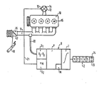
- FIG. 11 A particularly simple exemplary embodiment for carrying out the method according to the invention is shown in the drawing.
- 11 the intake pipe of a four-cylinder, four-stroke internal combustion engine 10, the ignition distributor 12 of which has a low-voltage connection 13 (terminal 1) and is on its high-voltage electrodes 14 with the spark plugs 15 of the internal combustion engine via ignition cables, not shown.
- the intake manifold 11 leads from the carburetor indicated at 16, which is not shown in detail, the throttle valve 17 of which can be adjusted by means of an accelerator pedal 18, to the individual cylinders of the internal combustion engine 10.
- the measuring and evaluation device G contains two sensors, namely a pressure sensor S1 connected to the intake pipe 11 via a hose line 20, which detects the intake pipe pressure p which prevails in the intake pipe 11 and is dependent on the position of the throttle valve 17 and the engine speed S is determined and, for shifting the characteristic curve, forms the difference compared to a comparison value p 0 .
- the second sensor S2 is used to determine the respective speed n M of the internal combustion engine and is connected to the distribution terminal 13 via an electrical line 21.
- the constant C depends on that engine and vehicle type and can be taken into account by means of an insertable module M. In this way it is possible to provide a common evaluation device for different types of motor vehicles.
- the integration can be started using a start button 23 and stopped using a stop button 24.
- claims 3, 6, 12, 16, 17, 22, 23, 24 and 25 and 29 are particularly realized.
- the possibility of placing the pressure sensor in the evaluation circuit reduces the demands on the pressure sensor with regard to resistance to shaking and the temperature range and saves a sensor housing.
- the "sensor” engine speed is realized by an extended evaluation circuit.
- the additional driving speed sensor is useful if consumption values related to the route are to be displayed immediately and are not to be calculated by the driver using the odometer on the speedometer.
- This arrangement of the factor-determining components makes it possible to produce a uniform measuring system for many types of motor vehicles, in which case only this module has to be used for the specific type of motor vehicle.
- the pressure system according to the invention can subsequently be easily and quickly connected to any existing system (connection to the intake manifold pressure) and does not require any changes to the existing metering systems.
- the pressure measuring system can be retrofitted.
- the installation of systems with intervention in the gasoline line is much more difficult for laymen and workshops.
- the two sensors, pressure sensor and engine speed sensor can be integrated into the evaluation circuit.
Landscapes
- Physics & Mathematics (AREA)
- General Physics & Mathematics (AREA)
- Fluid Mechanics (AREA)
- Measuring Fluid Pressure (AREA)
- Combined Controls Of Internal Combustion Engines (AREA)
- Hybrid Electric Vehicles (AREA)
- Measuring Volume Flow (AREA)
Applications Claiming Priority (2)
| Application Number | Priority Date | Filing Date | Title |
|---|---|---|---|
| DE3027470 | 1980-07-19 | ||
| DE19803027470 DE3027470A1 (de) | 1980-07-19 | 1980-07-19 | Verfahren zur messung des kraftstoffverbrauchs |
Publications (2)
| Publication Number | Publication Date |
|---|---|
| EP0044403A2 true EP0044403A2 (fr) | 1982-01-27 |
| EP0044403A3 EP0044403A3 (fr) | 1984-07-04 |
Family
ID=6107641
Family Applications (1)
| Application Number | Title | Priority Date | Filing Date |
|---|---|---|---|
| EP81104534A Withdrawn EP0044403A3 (fr) | 1980-07-19 | 1981-06-12 | Procédé pour la mesure de la consommation de combustible |
Country Status (3)
| Country | Link |
|---|---|
| EP (1) | EP0044403A3 (fr) |
| JP (1) | JPS5752821A (fr) |
| DE (1) | DE3027470A1 (fr) |
Cited By (1)
| Publication number | Priority date | Publication date | Assignee | Title |
|---|---|---|---|---|
| GB2127545A (en) * | 1982-07-28 | 1984-04-11 | Univ Open | Fuel consumption indicator and travel cost display system |
Families Citing this family (3)
| Publication number | Priority date | Publication date | Assignee | Title |
|---|---|---|---|---|
| EP0094370A3 (fr) * | 1982-04-28 | 1985-08-21 | Ing. Franz Mitterbauer Gesellschaft m.b.H. & Co. KG. | Dispositif pour la détermination de la consommation de combustible d'un moteur à combustion interne |
| DE3245546A1 (de) * | 1982-12-09 | 1984-06-14 | Bosch und Pierburg System oHG, 4040 Neuss | Vorrichtung zur bestimmung des momentanen kraftstoffverbrauchs von brennkraftmaschinen |
| JPS6062931A (ja) * | 1983-09-09 | 1985-04-11 | 泰東製綱株式会社 | 定置網の垣網 |
Family Cites Families (5)
| Publication number | Priority date | Publication date | Assignee | Title |
|---|---|---|---|---|
| DE2312820A1 (de) * | 1973-03-15 | 1974-09-19 | Gerhard Dipl Ing Ebeling | Direktanzeigender kraftstoffverbrauchsmesser fuer kraftfahrzeuge |
| JPS5731085B2 (fr) * | 1975-01-07 | 1982-07-02 | ||
| JPS5525368Y2 (fr) * | 1975-01-27 | 1980-06-18 | ||
| US4031363A (en) * | 1976-05-17 | 1977-06-21 | General Time Corporation | Display apparatus for automotive vehicles |
| IT1071809B (it) * | 1976-11-02 | 1985-04-10 | Fiat Spa | Sistema di segnalazione per un autoveicolo azionato da un motore a combustione interna e provvisto di un cambio di velocita a piu rapportiatto a fornire al guidatore una segnalazione relativa al rapporto di marcia da adottare per realizzare il minor consumo |
-
1980
- 1980-07-19 DE DE19803027470 patent/DE3027470A1/de not_active Withdrawn
-
1981
- 1981-06-12 EP EP81104534A patent/EP0044403A3/fr not_active Withdrawn
- 1981-07-17 JP JP56110952A patent/JPS5752821A/ja active Pending
Cited By (1)
| Publication number | Priority date | Publication date | Assignee | Title |
|---|---|---|---|---|
| GB2127545A (en) * | 1982-07-28 | 1984-04-11 | Univ Open | Fuel consumption indicator and travel cost display system |
Also Published As
| Publication number | Publication date |
|---|---|
| JPS5752821A (en) | 1982-03-29 |
| DE3027470A1 (de) | 1982-02-25 |
| EP0044403A3 (fr) | 1984-07-04 |
Similar Documents
| Publication | Publication Date | Title |
|---|---|---|
| DE19740969B4 (de) | Verfahren zum Betreiben einer Brennkraftmaschine und Brennkraftmaschine | |
| DE4443517B4 (de) | Einrichtung zur Lasterfassung bei einer Brennkraftmaschine | |
| DE4225198C2 (de) | Verfahren und Vorrichtung zur Steuerung der Kraftstoffmenge für eine Brennkraftmaschine | |
| DE3226353A1 (de) | Geraet zum steuern des energieumwandlungsprozesses eines motors mit innerer verbrennung | |
| DE3238153A1 (de) | Verfahren und vorrichtung zum steuern einer brennkraftmaschine | |
| DE102019111406A1 (de) | Verfahren zum bewerten des status der kraftstoff-drehmoment-effizienz eines verbrennungsmotors | |
| DE19920691A1 (de) | Motorsteuerungssystem | |
| DE102007051873B4 (de) | Verfahren und Vorrichtung zum Betreiben einer Brennkraftmaschine | |
| DE3513086A1 (de) | Vorrichtung fuer eine brennkraftmaschine zur beeinflussung von betriebsparametern | |
| EP0044403A2 (fr) | Procédé pour la mesure de la consommation de combustible | |
| EP0229643A2 (fr) | Système d'allumage pour moteur à combustion interne | |
| DE19622105B4 (de) | Verfahren zur Steuerung einer zumindest mit Brenngas betreibbaren Brennkraftmaschine, insbesondere für Kraftfahrzeuge | |
| DE4434884C2 (de) | Verfahren zur Bestimmung der Dichte der in einen Automobilmotor eingelassenen Ansaugluft | |
| DE2731065A1 (de) | Verfahren und einrichtung zur anzeige des momentanen kraftstoffverbrauchs | |
| DE2829634A1 (de) | Mess- und ueberwachungsvorrichtung fuer den betriebszustand einer brennkraftmaschine | |
| DE19633680B4 (de) | Einrichtung zur Korrektur eines Meßfehlers | |
| DE3049158C2 (fr) | ||
| DE3519476A1 (de) | Vorrichtung zur steuerung des kraftstoff-luft-gemisches einer brennkraftmaschine | |
| DE3245546A1 (de) | Vorrichtung zur bestimmung des momentanen kraftstoffverbrauchs von brennkraftmaschinen | |
| EP0021023B1 (fr) | Dispositif pour déterminer la consommation momentanée en carburant de moteurs à injection de carburant | |
| DE3417495C2 (de) | Verfahren und Vorrichtung zum Bestimmen der von einer Brennkraftmaschine angesaugten Luftmenge | |
| DE19702393A1 (de) | Verfahren zur Bestimmung des Kraftstoffverbrauches eines Fahrzeuges | |
| DE3117951C2 (de) | Service-Intervall-Anzeigesystem für Kraftfahrzeuge | |
| EP0737805B1 (fr) | Dispositif pour déterminer un signal de charge pour un moteur à combustion interne | |
| DE3346548A1 (de) | Anordnung zur ermittlung und anzeige des kraftstoffverbrauchs in fahrzeugen |
Legal Events
| Date | Code | Title | Description |
|---|---|---|---|
| PUAI | Public reference made under article 153(3) epc to a published international application that has entered the european phase |
Free format text: ORIGINAL CODE: 0009012 |
|
| 17P | Request for examination filed |
Effective date: 19810612 |
|
| AK | Designated contracting states |
Designated state(s): DE FR GB IT |
|
| PUAL | Search report despatched |
Free format text: ORIGINAL CODE: 0009013 |
|
| AK | Designated contracting states |
Designated state(s): DE FR GB IT |
|
| STAA | Information on the status of an ep patent application or granted ep patent |
Free format text: STATUS: THE APPLICATION IS DEEMED TO BE WITHDRAWN |
|
| 18D | Application deemed to be withdrawn |
Effective date: 19851220 |
|
| RIN1 | Information on inventor provided before grant (corrected) |
Inventor name: BOLLHAGEN, HEINS Inventor name: WOCHER, BERTHOLD, DR. DIPL.-ING. Inventor name: HANDTMANN, DIETER, DR. DIPL.-PHYS. Inventor name: ABT, JUERGEN |