EP0044468A2 - Elément de tuyauterie à isolation thermique et système de tuyauterie comportant un tel élément et procédés de fabrication dudit élément et dudit système de tuyauterie - Google Patents
Elément de tuyauterie à isolation thermique et système de tuyauterie comportant un tel élément et procédés de fabrication dudit élément et dudit système de tuyauterie Download PDFInfo
- Publication number
- EP0044468A2 EP0044468A2 EP81105317A EP81105317A EP0044468A2 EP 0044468 A2 EP0044468 A2 EP 0044468A2 EP 81105317 A EP81105317 A EP 81105317A EP 81105317 A EP81105317 A EP 81105317A EP 0044468 A2 EP0044468 A2 EP 0044468A2
- Authority
- EP
- European Patent Office
- Prior art keywords
- pipe
- heat
- elements
- useful
- layer
- Prior art date
- Legal status (The legal status is an assumption and is not a legal conclusion. Google has not performed a legal analysis and makes no representation as to the accuracy of the status listed.)
- Granted
Links
- 238000004519 manufacturing process Methods 0.000 title claims abstract description 13
- 238000000034 method Methods 0.000 title claims description 17
- 239000010410 layer Substances 0.000 claims abstract description 62
- 239000011241 protective layer Substances 0.000 claims abstract description 40
- 238000009413 insulation Methods 0.000 claims abstract description 35
- 239000000463 material Substances 0.000 claims description 43
- 239000006260 foam Substances 0.000 claims description 14
- 229910000831 Steel Inorganic materials 0.000 claims description 12
- 239000010959 steel Substances 0.000 claims description 12
- 230000000694 effects Effects 0.000 claims description 11
- 239000011810 insulating material Substances 0.000 claims description 10
- 229920003023 plastic Polymers 0.000 claims description 10
- 239000004033 plastic Substances 0.000 claims description 10
- 238000007789 sealing Methods 0.000 claims description 8
- 229920005830 Polyurethane Foam Polymers 0.000 claims description 7
- 238000010276 construction Methods 0.000 claims description 7
- 239000011496 polyurethane foam Substances 0.000 claims description 7
- 238000004873 anchoring Methods 0.000 claims description 6
- 230000001427 coherent effect Effects 0.000 claims description 5
- 230000007797 corrosion Effects 0.000 claims description 5
- 238000005260 corrosion Methods 0.000 claims description 5
- 239000003365 glass fiber Substances 0.000 claims description 5
- 229910052500 inorganic mineral Inorganic materials 0.000 claims description 5
- 239000011707 mineral Substances 0.000 claims description 5
- 238000006116 polymerization reaction Methods 0.000 claims description 5
- 229920001971 elastomer Polymers 0.000 claims description 4
- 239000011152 fibreglass Substances 0.000 claims description 4
- 239000007788 liquid Substances 0.000 claims description 4
- 239000005060 rubber Substances 0.000 claims description 4
- KXGFMDJXCMQABM-UHFFFAOYSA-N 2-methoxy-6-methylphenol Chemical compound [CH]OC1=CC=CC([CH])=C1O KXGFMDJXCMQABM-UHFFFAOYSA-N 0.000 claims description 3
- 230000008859 change Effects 0.000 claims description 3
- 239000007849 furan resin Substances 0.000 claims description 3
- 229910052751 metal Inorganic materials 0.000 claims description 3
- 239000002184 metal Substances 0.000 claims description 3
- 239000000203 mixture Substances 0.000 claims description 3
- 229920001568 phenolic resin Polymers 0.000 claims description 3
- 239000005011 phenolic resin Substances 0.000 claims description 3
- 235000019353 potassium silicate Nutrition 0.000 claims description 3
- NTHWMYGWWRZVTN-UHFFFAOYSA-N sodium silicate Chemical compound [Na+].[Na+].[O-][Si]([O-])=O NTHWMYGWWRZVTN-UHFFFAOYSA-N 0.000 claims description 3
- 239000007787 solid Substances 0.000 claims description 3
- 239000000853 adhesive Substances 0.000 claims description 2
- 230000001070 adhesive effect Effects 0.000 claims description 2
- 239000003153 chemical reaction reagent Substances 0.000 claims description 2
- 239000004744 fabric Substances 0.000 claims description 2
- 125000006850 spacer group Chemical group 0.000 claims description 2
- 229920003002 synthetic resin Polymers 0.000 claims description 2
- 239000000057 synthetic resin Substances 0.000 claims description 2
- 229920001187 thermosetting polymer Polymers 0.000 claims description 2
- 238000013007 heat curing Methods 0.000 claims 1
- 230000035699 permeability Effects 0.000 claims 1
- XLYOFNOQVPJJNP-UHFFFAOYSA-N water Substances O XLYOFNOQVPJJNP-UHFFFAOYSA-N 0.000 abstract description 24
- 238000009423 ventilation Methods 0.000 abstract description 5
- 230000006378 damage Effects 0.000 description 7
- 230000000149 penetrating effect Effects 0.000 description 3
- 230000035515 penetration Effects 0.000 description 3
- 230000008901 benefit Effects 0.000 description 2
- 238000006243 chemical reaction Methods 0.000 description 2
- 238000000576 coating method Methods 0.000 description 2
- 230000007547 defect Effects 0.000 description 2
- 230000006866 deterioration Effects 0.000 description 2
- 239000003673 groundwater Substances 0.000 description 2
- 238000010438 heat treatment Methods 0.000 description 2
- 239000012784 inorganic fiber Substances 0.000 description 2
- 239000012774 insulation material Substances 0.000 description 2
- 229920002635 polyurethane Polymers 0.000 description 2
- 239000004814 polyurethane Substances 0.000 description 2
- 230000008439 repair process Effects 0.000 description 2
- 239000002689 soil Substances 0.000 description 2
- 239000000126 substance Substances 0.000 description 2
- 229920001169 thermoplastic Polymers 0.000 description 2
- 239000004416 thermosoftening plastic Substances 0.000 description 2
- JOYRKODLDBILNP-UHFFFAOYSA-N Ethyl urethane Chemical compound CCOC(N)=O JOYRKODLDBILNP-UHFFFAOYSA-N 0.000 description 1
- 239000006244 Medium Thermal Substances 0.000 description 1
- 244000089486 Phragmites australis subsp australis Species 0.000 description 1
- 239000004698 Polyethylene Substances 0.000 description 1
- 230000009471 action Effects 0.000 description 1
- 229910052782 aluminium Inorganic materials 0.000 description 1
- XAGFODPZIPBFFR-UHFFFAOYSA-N aluminium Chemical compound [Al] XAGFODPZIPBFFR-UHFFFAOYSA-N 0.000 description 1
- 230000015572 biosynthetic process Effects 0.000 description 1
- 230000000903 blocking effect Effects 0.000 description 1
- 229920002301 cellulose acetate Polymers 0.000 description 1
- 239000004568 cement Substances 0.000 description 1
- 239000011248 coating agent Substances 0.000 description 1
- 238000001816 cooling Methods 0.000 description 1
- 230000008878 coupling Effects 0.000 description 1
- 238000010168 coupling process Methods 0.000 description 1
- 238000005859 coupling reaction Methods 0.000 description 1
- 230000000254 damaging effect Effects 0.000 description 1
- 230000007812 deficiency Effects 0.000 description 1
- 230000002950 deficient Effects 0.000 description 1
- 230000008030 elimination Effects 0.000 description 1
- 238000003379 elimination reaction Methods 0.000 description 1
- 238000005516 engineering process Methods 0.000 description 1
- 230000007613 environmental effect Effects 0.000 description 1
- 238000001704 evaporation Methods 0.000 description 1
- 230000008020 evaporation Effects 0.000 description 1
- 230000004992 fission Effects 0.000 description 1
- 238000009415 formwork Methods 0.000 description 1
- 239000011521 glass Substances 0.000 description 1
- 230000009931 harmful effect Effects 0.000 description 1
- 230000002209 hydrophobic effect Effects 0.000 description 1
- 230000001771 impaired effect Effects 0.000 description 1
- 238000011065 in-situ storage Methods 0.000 description 1
- 230000007774 longterm Effects 0.000 description 1
- 239000002985 plastic film Substances 0.000 description 1
- 229920006255 plastic film Polymers 0.000 description 1
- 229920000728 polyester Polymers 0.000 description 1
- -1 polyethylene Polymers 0.000 description 1
- 229920000573 polyethylene Polymers 0.000 description 1
- 230000000379 polymerizing effect Effects 0.000 description 1
- 239000011148 porous material Substances 0.000 description 1
- 238000009417 prefabrication Methods 0.000 description 1
- 230000002265 prevention Effects 0.000 description 1
- 230000008569 process Effects 0.000 description 1
- 230000001681 protective effect Effects 0.000 description 1
- 230000005855 radiation Effects 0.000 description 1
- 230000009467 reduction Effects 0.000 description 1
- 230000002277 temperature effect Effects 0.000 description 1
- 238000004804 winding Methods 0.000 description 1
Images


Classifications
-
- F—MECHANICAL ENGINEERING; LIGHTING; HEATING; WEAPONS; BLASTING
- F16—ENGINEERING ELEMENTS AND UNITS; GENERAL MEASURES FOR PRODUCING AND MAINTAINING EFFECTIVE FUNCTIONING OF MACHINES OR INSTALLATIONS; THERMAL INSULATION IN GENERAL
- F16L—PIPES; JOINTS OR FITTINGS FOR PIPES; SUPPORTS FOR PIPES, CABLES OR PROTECTIVE TUBING; MEANS FOR THERMAL INSULATION IN GENERAL
- F16L59/00—Thermal insulation in general
- F16L59/12—Arrangements for supporting insulation from the wall or body insulated, e.g. by means of spacers between pipe and heat-insulating material; Arrangements specially adapted for supporting insulated bodies
- F16L59/123—Anchoring devices; Fixing arrangements for preventing the relative longitudinal displacement of an inner pipe with respect to an outer pipe, e.g. stress cones
-
- F—MECHANICAL ENGINEERING; LIGHTING; HEATING; WEAPONS; BLASTING
- F16—ENGINEERING ELEMENTS AND UNITS; GENERAL MEASURES FOR PRODUCING AND MAINTAINING EFFECTIVE FUNCTIONING OF MACHINES OR INSTALLATIONS; THERMAL INSULATION IN GENERAL
- F16L—PIPES; JOINTS OR FITTINGS FOR PIPES; SUPPORTS FOR PIPES, CABLES OR PROTECTIVE TUBING; MEANS FOR THERMAL INSULATION IN GENERAL
- F16L59/00—Thermal insulation in general
- F16L59/02—Shape or form of insulating materials, with or without coverings integral with the insulating materials
-
- F—MECHANICAL ENGINEERING; LIGHTING; HEATING; WEAPONS; BLASTING
- F16—ENGINEERING ELEMENTS AND UNITS; GENERAL MEASURES FOR PRODUCING AND MAINTAINING EFFECTIVE FUNCTIONING OF MACHINES OR INSTALLATIONS; THERMAL INSULATION IN GENERAL
- F16L—PIPES; JOINTS OR FITTINGS FOR PIPES; SUPPORTS FOR PIPES, CABLES OR PROTECTIVE TUBING; MEANS FOR THERMAL INSULATION IN GENERAL
- F16L59/00—Thermal insulation in general
- F16L59/14—Arrangements for the insulation of pipes or pipe systems
- F16L59/16—Arrangements specially adapted to local requirements at flanges, junctions, valves or the like
- F16L59/18—Arrangements specially adapted to local requirements at flanges, junctions, valves or the like adapted for joints
- F16L59/20—Arrangements specially adapted to local requirements at flanges, junctions, valves or the like adapted for joints for non-disconnectable joints
-
- F—MECHANICAL ENGINEERING; LIGHTING; HEATING; WEAPONS; BLASTING
- F16—ENGINEERING ELEMENTS AND UNITS; GENERAL MEASURES FOR PRODUCING AND MAINTAINING EFFECTIVE FUNCTIONING OF MACHINES OR INSTALLATIONS; THERMAL INSULATION IN GENERAL
- F16L—PIPES; JOINTS OR FITTINGS FOR PIPES; SUPPORTS FOR PIPES, CABLES OR PROTECTIVE TUBING; MEANS FOR THERMAL INSULATION IN GENERAL
- F16L59/00—Thermal insulation in general
- F16L59/14—Arrangements for the insulation of pipes or pipe systems
- F16L59/16—Arrangements specially adapted to local requirements at flanges, junctions, valves or the like
- F16L59/21—Arrangements specially adapted to local requirements at flanges, junctions, valves or the like adapted for expansion-compensation devices
-
- F—MECHANICAL ENGINEERING; LIGHTING; HEATING; WEAPONS; BLASTING
- F16—ENGINEERING ELEMENTS AND UNITS; GENERAL MEASURES FOR PRODUCING AND MAINTAINING EFFECTIVE FUNCTIONING OF MACHINES OR INSTALLATIONS; THERMAL INSULATION IN GENERAL
- F16L—PIPES; JOINTS OR FITTINGS FOR PIPES; SUPPORTS FOR PIPES, CABLES OR PROTECTIVE TUBING; MEANS FOR THERMAL INSULATION IN GENERAL
- F16L59/00—Thermal insulation in general
- F16L59/14—Arrangements for the insulation of pipes or pipe systems
- F16L59/16—Arrangements specially adapted to local requirements at flanges, junctions, valves or the like
- F16L59/22—Arrangements specially adapted to local requirements at flanges, junctions, valves or the like adapted for bends
Definitions
- the invention relates to piping elements and connecting elements of heat-insulated piping systems, furthermore to the method for producing the piping elements and connecting elements and their assembly in a piping system.
- the heating and utility water pipes of district heating, as well as the other pipes for the conveyance of hot water, industrial steam and cold water, as well as the pipes of the cooling and oil industry play in the circle of the known pipelines used to convey liquid and / or gaseous materials an important role; Thermal insulation must be provided for these lines. To isolate the he - mentioned pipelines, as well as to protect the 'line pipe and the thermal insulation itself many solutions are known.
- connection between the casing pipes and the profiles is made with the aid of a seal with rubber rings or a sleeve made of a thermally shrinking plastic.
- each of said seal solutions is the requirement of perfect Wasserun prepare for the production of a product.
- the foam layer becomes damaged, as a result of the deterioration in the thermal insulation, the temperature of the plastic jacket tube will rise to such an extent that the jacket tube is completely destroyed.
- the penetration of water causes the corrosion of the steel pipe, which, at a high operating temperature, leads to the short-term deterioration of the steel pipe.
- the pipes can in no way be repaired in a satisfactory manner, with a single defect causing the damage of a long distance. Structural damage increases the heat loss of the pipe system to a significant extent, which causes significant energy losses.
- Another damaging effect can be caused by the amount of water trapped in the closed system during assembly or assembly.
- the removal of the amount of water thus enclosed is not solved in the known solutions.
- Certain synthetic pipes such as PVC pipes are not suitable for enduring the long-term exposure to solar radiation, so the cables arranged on the floor or on pillars or in the open cannot be made with such coatings.
- the thermoplastic pipes generally used cannot be subjected to a higher thermal load. The circumstances mentioned limit the range of use and in many cases the full capacity of the costly manufacturing facilities cannot be used. Furthermore, there is the fact that the plastics are relatively easily damaged, so the protection of the pipes insulated with a synthetic jacket against such effects, the occurrence of which must be expected during use in practice re 1, can by no means be regarded as completely satisfactory.
- the aim of the invention was to develop a heat-insulated piping system, the piping and connecting elements of which ensure the elimination of the deficiencies mentioned in the piping systems built from the elements mentioned.
- pre-insulated pipe elements and lines can be produced in the same way, which can be used as air lines, underground lines or as insulated underwater lines exposed to soil water pressure.
- the flexibility hidden in the process is intended to enable economical use within the broadest scope of expenditure. Enabling the general applicability of the insulating material with out - recorded insulating capabilities should also lead there to a saving of heat energy in the operation of the lines where the use of such pre-insulated pipes were previously impossible, such as in air ducts and under the ground water routed cables.
- the pre-insulation carried out in the factory is said to significantly reduce the work to be carried out on site and hours and to significantly shorten the assembly time and assembly.
- the invention is based on the finding by using a suitable comforting method and by the appropriate one.
- Choice and composition of the materials, under application and the same production systems, an insulation and protection system adapting to the respective requirements can be produced on the conduit / useful pipe / which, in comparison to the simple protection system previously used in general, has a secondary and a tertiary protection system represents.
- the insulation and protection system and the protection of the conduit are designed in the manner described, the primary external protection offered by the casing pipe and that which is independent of the damage, the leakage of the connections and the presence of the water enclosed in the course of the erection, provide perfect protection. free-functioning internal protection system / or several protection systems / due security against damage. From the expediently selected components, through the suitable choice of the plastics, the application of the method according to the invention to the outer part delimiting the jacket tube and the associated points brings about a coherent protective layer with a closed structure, which is elastic and opposite the mat tube mechanical damage is protected, therefore ensuring water tightness even in extreme cases.
- a layer designed with air passages is produced on the inner part of the insulation, which layer is capable of fulfilling the function of steam removal, as a result of which the water vapor or other gaseous fission product stuck in the insulating material escapes into a suitable large air space / e.g. into a fitting shaft / enabled and, as a success, the possibly defective effect is eliminated.
- the vapor-dissipating layer which is expediently produced from an inorganic fiber material, fulfills a heat-insulating function and protects the heat-insulating layer made of polyurethane foam, which is more sensitive to the immediate high levels of heat.
- the useful pipe is a conventional steel pipe or a pipe made of other basic material and resistant to the chemical action, temperature and pressure of the medium being conveyed, e.g. is a glass fiber reinforced plastic tube or synthetic resin concrete tube.
- the pre-insulated piping system is suitable for general use if the previously described inner protection system is paired with a casing pipe which is well tolerant of the environmental and temperature effects and is solid to the required extent.
- thermosetting plastic tube or a plastic-bound jacket tube with mineral filling With medium thermal.
- the thermoplastic synthetic jacket pipes have proven their worth. Polished pipelines arranged outdoors can be designed to be quite advantageous if a metal pipe with a small wall thickness, which tolerates the atmospheric conditions and which is either corrosion-resistant in the material or is provided with a separate corrosion protection, is used as the casing pipe.
- a spirally folded or welded aluminum tube or the like is used as the sheet metal tube.
- the invention is associated with numerous advantageous and novel multi-effects which cannot be found in the currently known solutions which serve similar purposes.
- an isolated. Pipeline system that is resistant to the atmospheric and force effects to the desired extent, prevents the ingress of water with multiple security, whose thermal insulation reduces heat losses to the technical minimum and whose need for living work on the construction site associated with the pipe length unit is extremely low assembly the line from the pre-insulated elements can be made up-to-date, well organized and mechanized, the activities related to the upgrading, formwork and lowering of the soil water level can be partially omitted or reduced, the entire implementation taking a shorter time span.
- the invention relates to a heat-insulated piping system, as well as to its operational prefabrication and assembly assembly in situ, which piping system is used to convey liquid and / or gaseous media, in particular heat-carrying media in an insulated Pipe is used, which consists of the inner tube known per se, the concentric outer jacket tube and the thermal insulating material filling the space between the two tubes, and in the sense of the invention a waterproof inner protective layer at the interface of the thermal insulation and the jacket tube. is designed, while a possible ventilation layer is formed on the part adjoining the inner useful pipe, which, after assembly, is expediently connected to the service or fitting shaft of large air space.
- the straight or curved pipes prefabricated in the factory, the branches of the pipe sections, and the anchoring pipe sections are secured by means of a coupling that prevents water from penetrating but enables ventilation along the inner pipe, as well as with the known blocking and Control valves at the construction site assembled in a pipe system, in the improved, previously heat-insulated Pipe system prevents the waterproof protective layer inside the casing pipe from penetrating the water resulting from the leakage of the casing pipe system, thereby eliminating the reduction in the insulating capacity of the heat-insulating layer and generally eliminating the risk of corrosion in the commercial pipe which is usually made of steel.
- jacket pipe refers to the outer shell that is in direct contact with the external environment, which may consist of several pieces, or the material of which may change along the length of the pipeline system.
- the layer adjacent to the useful pipe and provided with the air passages ensures the escape of the moisture enclosed during assembly, as a result of which its chemical and mechanical harmful effects in the heat insulation layer are eliminated.
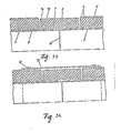
- the inner / useful pipe 1 for example made of steel, is encased by the vapor-removing layer 2, a layer consisting of inorganic fiber material / for example glass fiber material and provided with open air passages.
- the heat-insulating layer 3 is arranged touching the layer, which is expediently formed by a hard polyurethane foam with open pores, phenolic resin foam, furan resin foam or water glass foam.
- the phenolic resin foam, the furan resin foam and the water glass foam can be made hydrophobic. The advantage of these materials is the high degree of thermal tolerance.
- the thermal insulation layer 3 is coherently encased by one or more / waterproof safety protective layer / s / 4, which is made of a waterproof plastic, suitably soft polyurethane, polyester, polyethylene, cellulose acetate or a material
- the basic requirement of the safety protective layer is that it has a correspondingly high elongation at break and adhere well to the limiting materials.
- the outermost layer of the construction is formed by the coherent, waterproof jacket tube 5, which has a corresponding rigidity and is resistant to the external media effects.
- the above-described polymerization reaction allows multiple protective layers to be formed on the inner wall of the jacket tube 5. Likewise, several protective layers can be glued or placed on the inner wall of the casing tube 5. In this case, the individual waterproof protective layers can be made of the same or different materials.
- waterproof safety protective layer 4 is designed or only in individual sections of the wall of the casing tube 5. less on individual sections of the wall of the casing tube, more on other sections from the waterproof protective layer 4.
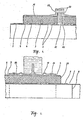
- FIGS. 3a and 3b The assembly of the elements of the pipeline system forming the subject of the invention is described in connection with FIGS. 3a and 3b. Assembly begins with the production of the continuity of the inner useful pipe 1 with the weld seam 6.
- the described multiple protective pipe system turns the continuity of the vapor-removing layer 2 provided with air passages by attaching the vapor-removing layer consisting of the fibrous heat-insulating material Layer 7 made.
- a waterproof layer 14 is formed on this by hand application, which expediently consists of the same material as the inner waterproof protective layer 4 or a plastic that is compatible with it. When producing the layer, care must be taken that it is connected and that the gaps in the initial section of the casing tube 5 are completely filled.
- the thermal insulation layer 3 is supplemented in place; in our example, prefabricated shells 8 made of hard polyurethane are attached.
- This work phase is followed by the production of part 16 of the waterproof protective layer 4; in this way the waterway was blocked off many times.
- the continuity of the casing tube 5 with the sleeve 18 with the rubber ring 12 is secured. posed.
- the inner elastic, watertight safety protective layer 4 is not designed continuously over the entire length of the tube section.
- the foam layer in the pipeline can be divided into sections and blocked off per section, whereby the effect of damage is only exerted on the given section.
- this solution can also be used with the pipes continuously provided with the waterproof protective layer 4.
- the assembly technology described above can also be used for the repair of pipes with a traditional structure which are produced in the customary manner and insulated in the jacket pipe.
- the main advantage shows that the effect of Repair, spreads over the actually treated section.
- the fixed point element providing the anchoring can be implemented, for example, in the embodiment shown in FIG.
- the fixed point element is attached to the one on the useful tube 1.
- Washer 20 provided, which are made of a suitable strength, e.g. Sheet steel is made and is used to dissipate the forces occurring on the useful pipe 1 from various origins and to maintain the line point in its fixed position.
- the disk 20 is provided in the vicinity of the useful pipe 1 with the air-guiding openings 21, expediently with bores, which ensure the continuity of the air passages of the vapor-removing layer along the working pipe 1.
- the jacket of the fixed point element is formed by two flanged tubes 19, which are arranged on both sides of the disk of the fixed point element with the interposition of a sealing plate 22 known per se and are connected with the screws 23.
- the waterproof protective layer 4 can also be configured in the fixed point element.
- the line or at certain points. certain sections, expediently the vapor-dissipating layer 2 is connected to a large air space in the insulation terminations in the shafts / FIG. 5 /, and in such a way that on the useful pipe 1 the vapor-dissipating layer 2 / which is expediently produced from a fibrous inorganic thermal insulation material /, continuously , on the inside of the building: protruding pipe section, beyond the insulation limit becomes.
- the waterproof protective layer 4 a water-impermeable film is produced. In this way, the penetration of the water is practically ruled out, while at the same time the possibility of ventilation of the insulation system and evaporation of the water from the insulation material is maintained.
- the embodied according to the invention can insulated pipe of a building to be performed shown in Figure 5 o wall sleeve 24 through the wall with the aid of; the sleeve has a disk-shaped projection for fastening in the wall and for performing the water insulation in a manner known per se.
- the wall sleeve 24 is expediently provided with two inner grooves each, which enable the design of the double-security seal in the outer pair of grooves by the arrangement of the sealing rings 12, while with the aid of the filling holes 13 present in the inner pair of grooves one with the material of the waterproof protective layer 4 matching material is filled.
- a known spring-body compensator 26 is used in the assembly of the heat-insulated pipe elements with improved properties, the pipe element 33 of which is attached to the useful pipe 1 / in the case of a steel pipe with the weld 6 /.
- the extension of the vapor-removing layer 2 to the limit of the compensator waves is carried out by the arrangement of the fibrous heat insulating material 27.
- the continuity of the heat insulation in the area of the spring body compensator 26 is achieved by using a half-shell-shaped heat insulation layer 26 moderately made of hard polyurethane foam on the conduit, and also a half-shell-shaped heat insulation layer 29, which places the clothing tube of the spring body compensator 26.
- the heat insulation layers 28, 29 are fixed in their position, the gap between them is closed with the cement 30, which expediently consists of a less waterproof protective layer 4 of identical material, but has the desired consistency.
- the sleeve 31 is pulled over the spring compensator 26; the sleeve is designed in its central section with an enlarged diameter, so it can be suitably provided on the inside with the thermal insulation 32 made of hard polyurethane foam, whereby the full thermal insulation of the piping system is also achieved in this section.
- the two ends of the sleeve 31 are advantageously each provided with two internal grooves. those, the outer pair serves to receive the sealing ring 12, while the filling bores 13 of the inner pair enable the filling of a filling material / identical to the material of the waterproof protective layer 4 /.
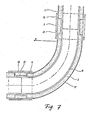
- FIG. 7 illustrates an exemplary embodiment of the heat-insulated curved tube according to the invention, and a further possibility for connecting the elements.
- the curved pipe 15 is present, which in our embodiment is provided with a sleeve 34 - for performing the adhesive connection.
- the jacket pipe 17 and the pipe 15 have a common center.
- both elbow pipes are filled with mineral material and made from a glass fiber reinforced plastic that hardens under the effect of heat; the waterproof protective layer 4 is bare applied to the ends of the jacket pipe.
- the space between the useful pipe and the jacket pipe is expediently filled with the heat insulating layer 3 made of rigid polyurethane foam.
- the conical end of the useful pipe is inserted into the sleeve 34 of the curved pipe 15 and - in our embodiment - glued to it.
- the heat-insulating half-shells 8 are put on and the sleeve 35 / which is expediently made of a glass fiber reinforced plastic / is pulled over the joint.
- the rubber rings 12 are inserted in the grooves of the sleeve in advance.
- the space between the sleeve 35 and the half-shells 8 is filled via the filling bore 36 with a material corresponding to the material of the waterproof protective layer 4; After the plastic has hardened, the continuity of the waterproof safety protective layer is guaranteed.
Landscapes
- Engineering & Computer Science (AREA)
- General Engineering & Computer Science (AREA)
- Mechanical Engineering (AREA)
- Thermal Insulation (AREA)
- Rigid Pipes And Flexible Pipes (AREA)
- Cable Accessories (AREA)
- Superconductors And Manufacturing Methods Therefor (AREA)
- Pipeline Systems (AREA)
- Pipe Accessories (AREA)
Priority Applications (1)
| Application Number | Priority Date | Filing Date | Title |
|---|---|---|---|
| AT81105317T ATE18093T1 (de) | 1980-07-17 | 1981-07-08 | Waermeisoliertes rohrleitungselement und rohrleitungssystem aus diesen rohrleitungselementen sowie verfahren zur herstellung des rohrleitungselementes und des rohrleitungssystems. |
Applications Claiming Priority (2)
| Application Number | Priority Date | Filing Date | Title |
|---|---|---|---|
| HU178180 | 1980-07-17 | ||
| HU80801781A HU181153B (en) | 1980-07-17 | 1980-07-17 | Pipeline for furthering medium requiring thermal insulation as well as method for making and repairing the pipeline |
Publications (3)
| Publication Number | Publication Date |
|---|---|
| EP0044468A2 true EP0044468A2 (fr) | 1982-01-27 |
| EP0044468A3 EP0044468A3 (en) | 1982-04-07 |
| EP0044468B1 EP0044468B1 (fr) | 1986-02-19 |
Family
ID=10956168
Family Applications (1)
| Application Number | Title | Priority Date | Filing Date |
|---|---|---|---|
| EP81105317A Expired EP0044468B1 (fr) | 1980-07-17 | 1981-07-08 | Elément de tuyauterie à isolation thermique et système de tuyauterie comportant un tel élément et procédés de fabrication dudit élément et dudit système de tuyauterie |
Country Status (7)
| Country | Link |
|---|---|
| EP (1) | EP0044468B1 (fr) |
| JP (1) | JPS5794195A (fr) |
| AT (1) | ATE18093T1 (fr) |
| DD (1) | DD202598A5 (fr) |
| DE (1) | DE3173800D1 (fr) |
| HU (1) | HU181153B (fr) |
| YU (1) | YU175281A (fr) |
Cited By (11)
| Publication number | Priority date | Publication date | Assignee | Title |
|---|---|---|---|---|
| EP0114269A1 (fr) * | 1982-12-17 | 1984-08-01 | INTERATOM Gesellschaft mit beschränkter Haftung | Canalisation pour fluides chauds et module pour son assemblage |
| EP0148717A3 (en) * | 1984-01-06 | 1985-08-14 | Jean-Marie Razny | Thermally insulated modular element for a fluid line |
| EP0229345A3 (en) * | 1986-01-02 | 1987-10-21 | Witzenmann Gmbh Metallschlauch-Fabrik Pforzheim | Device for elastic connection of two double-walled pipes |
| DE3934256A1 (de) * | 1988-10-14 | 1990-04-19 | Architektur Bauwesen Hochschul | Biegbares, waermegedaemmtes mantelrohrbauteil |
| DE3934252A1 (de) * | 1988-10-14 | 1990-04-19 | Architektur Bauwesen Hochschul | Biegbares, waermegedaemmtes mantelrohrbauteil |
| EP1431651A1 (fr) * | 2002-12-20 | 2004-06-23 | Mapress GmbH & Co. KG | Raccord de tuyau |
| GB2428627A (en) * | 2002-12-12 | 2007-02-07 | Kingspan Holdings | Hollow phenolic foam body |
| CN103075610A (zh) * | 2013-01-21 | 2013-05-01 | 南京苏夏工程设计有限公司 | 低能耗输送蒸汽管系统 |
| CN116576313A (zh) * | 2023-07-14 | 2023-08-11 | 济南城投设计有限公司 | 一种热力管网绝缘保温装置 |
| CN117869680A (zh) * | 2024-03-08 | 2024-04-12 | 东营新达德安新材料科技有限责任公司 | 一种玻纤带增强成型塑料复合管 |
| CN119778584A (zh) * | 2023-10-08 | 2025-04-08 | 长庆工程设计有限公司 | 一种塔器及管道的保冷装置及安装方法 |
Families Citing this family (6)
| Publication number | Priority date | Publication date | Assignee | Title |
|---|---|---|---|---|
| JPH04114194U (ja) * | 1991-03-27 | 1992-10-07 | 株式会社栗本鐵工所 | 断熱二重管 |
| JP2008298233A (ja) * | 2007-06-01 | 2008-12-11 | Shin Etsu Polymer Co Ltd | 耐火二層管継手及びその接続方法、並びに耐火二層管継手の施工管理方法 |
| TWM488573U (zh) * | 2014-02-11 | 2014-10-21 | First Piping & Corrosion Proof Industrail Co | 保溫管 |
| DE102019104536A1 (de) * | 2019-02-22 | 2020-08-27 | Sandvik Materials Technology Deutschland Gmbh | Rohrstruktur und Verfahren zum Herstellen einer solchen Rohrstruktur |
| US12479767B2 (en) | 2021-09-29 | 2025-11-25 | Owens Corning Intellectual Capital, Llc | Gypsum cement with reduced permeability |
| GB202302407D0 (en) * | 2023-02-20 | 2023-04-05 | Neale Tim Mosley | Insulated pipe assembly |
Family Cites Families (9)
| Publication number | Priority date | Publication date | Assignee | Title |
|---|---|---|---|---|
| CH447735A (de) * | 1965-11-30 | 1967-11-30 | Meier Schenk Arthur | Verbindung zweier ins Erdreich verlegter Isolierrohre an deren Stosstelle |
| NL165827C (nl) * | 1970-02-12 | 1981-05-15 | Wavin Bv | Buisverbinding voor buizen. |
| FR2050533A5 (en) * | 1969-06-17 | 1971-04-02 | Wanner Isofi Isolation | Buried insulated pipework for fluid trans- - port |
| DE2005839A1 (de) * | 1970-02-09 | 1971-08-19 | Waermetraeger Armaturen Gmbh | Wärmeisolierung mit porösen Abdeck teilen fur die Teile eines Warmeleitungs systems |
| GB1335055A (en) * | 1970-12-03 | 1973-10-24 | Wavin Bv | Pipe units or pipelines |
| US3744823A (en) * | 1971-03-01 | 1973-07-10 | Shaw Pipe Ind Ltd | High temperature pipeline joints |
| GB1390873A (en) * | 1972-09-29 | 1975-04-16 | Preload Technology | Piping systems for low temperature fluids and methods of forming the same |
| DE2812680A1 (de) * | 1978-03-23 | 1979-09-27 | Kaefer Isoliertechnik | Isolierelement |
| DE2901301A1 (de) * | 1979-01-15 | 1980-07-24 | Kabel Metallwerke Ghh | Muffe in einer durchgangs- bzw. abzweigverbindung fuer waermeisolierte leitungsrohre |
-
1980
- 1980-07-17 HU HU80801781A patent/HU181153B/hu unknown
-
1981
- 1981-07-08 AT AT81105317T patent/ATE18093T1/de active
- 1981-07-08 EP EP81105317A patent/EP0044468B1/fr not_active Expired
- 1981-07-08 DE DE8181105317T patent/DE3173800D1/de not_active Expired
- 1981-07-16 DD DD81231849A patent/DD202598A5/de unknown
- 1981-07-16 YU YU01752/81A patent/YU175281A/xx unknown
- 1981-07-17 JP JP56112062A patent/JPS5794195A/ja active Pending
Cited By (16)
| Publication number | Priority date | Publication date | Assignee | Title |
|---|---|---|---|---|
| EP0114269A1 (fr) * | 1982-12-17 | 1984-08-01 | INTERATOM Gesellschaft mit beschränkter Haftung | Canalisation pour fluides chauds et module pour son assemblage |
| EP0148717A3 (en) * | 1984-01-06 | 1985-08-14 | Jean-Marie Razny | Thermally insulated modular element for a fluid line |
| EP0229345A3 (en) * | 1986-01-02 | 1987-10-21 | Witzenmann Gmbh Metallschlauch-Fabrik Pforzheim | Device for elastic connection of two double-walled pipes |
| DE3934256A1 (de) * | 1988-10-14 | 1990-04-19 | Architektur Bauwesen Hochschul | Biegbares, waermegedaemmtes mantelrohrbauteil |
| DE3934252A1 (de) * | 1988-10-14 | 1990-04-19 | Architektur Bauwesen Hochschul | Biegbares, waermegedaemmtes mantelrohrbauteil |
| GB2428627B (en) * | 2002-12-12 | 2007-08-01 | Kingspan Holdings | Insulating phenolic foam sections |
| GB2428627A (en) * | 2002-12-12 | 2007-02-07 | Kingspan Holdings | Hollow phenolic foam body |
| GB2396327B (en) * | 2002-12-12 | 2007-07-25 | Kingspan Holdings | Insulating foam sections |
| US8343396B2 (en) | 2002-12-12 | 2013-01-01 | Kingspan Holdings (Irl) Limited | Insulating foam sections |
| EP1431651A1 (fr) * | 2002-12-20 | 2004-06-23 | Mapress GmbH & Co. KG | Raccord de tuyau |
| CN103075610A (zh) * | 2013-01-21 | 2013-05-01 | 南京苏夏工程设计有限公司 | 低能耗输送蒸汽管系统 |
| CN116576313A (zh) * | 2023-07-14 | 2023-08-11 | 济南城投设计有限公司 | 一种热力管网绝缘保温装置 |
| CN116576313B (zh) * | 2023-07-14 | 2023-09-15 | 济南城投设计有限公司 | 一种热力管网绝缘保温装置 |
| CN119778584A (zh) * | 2023-10-08 | 2025-04-08 | 长庆工程设计有限公司 | 一种塔器及管道的保冷装置及安装方法 |
| CN117869680A (zh) * | 2024-03-08 | 2024-04-12 | 东营新达德安新材料科技有限责任公司 | 一种玻纤带增强成型塑料复合管 |
| CN117869680B (zh) * | 2024-03-08 | 2024-05-31 | 东营新达德安新材料科技有限责任公司 | 一种玻纤带增强成型塑料复合管 |
Also Published As
| Publication number | Publication date |
|---|---|
| JPS5794195A (en) | 1982-06-11 |
| HU181153B (en) | 1983-06-28 |
| DD202598A5 (de) | 1983-09-21 |
| EP0044468A3 (en) | 1982-04-07 |
| EP0044468B1 (fr) | 1986-02-19 |
| YU175281A (en) | 1984-02-29 |
| DE3173800D1 (en) | 1986-03-27 |
| ATE18093T1 (de) | 1986-03-15 |
Similar Documents
| Publication | Publication Date | Title |
|---|---|---|
| EP0044468A2 (fr) | Elément de tuyauterie à isolation thermique et système de tuyauterie comportant un tel élément et procédés de fabrication dudit élément et dudit système de tuyauterie | |
| DE69229234T2 (de) | Schichtstoff | |
| DE2012558C2 (de) | Isoliertes Rohrleitungssystem, insbesondere Fernheizungsrohranlage | |
| DE3618334C1 (de) | Vortriebsrohr | |
| EP0017254B2 (fr) | Tuyau isolé thermiquement et procédé pour sa fabrication | |
| DE60013117T2 (de) | Isolierter rohraufbau und verfahren zu dessen herstellung | |
| DE69231133T2 (de) | Verfahren und Material zum Auskleiden von Rohren | |
| DE1285801B (de) | Im Erdreich zu verlegendes Verbundrohr | |
| DE69311803T2 (de) | Verfahren zum Verlegen vom Unterwasserrohrleitungen in tiefen Gewässern | |
| DE3600028C1 (de) | Vorrichtung zum elastischen Verbinden zweier Mantelrohrleitungen | |
| EP0260341B1 (fr) | Procédé de renovation d'une canalisation enterrée | |
| DE2743635C2 (de) | Wärmeisoliertes Rohr mit einem großen Durchmesser zum Transport von Fluiden hoher Temperatur | |
| DE3245462C2 (fr) | ||
| DD253658A5 (de) | Waermeisoliertes rohr aus mit fasern armiertem beton | |
| DE3700883A1 (de) | Verfahren zur erneuerung von begehbaren oder bekriechbaren geschlossenes profil aufweisenden linienfoermigen bauwerken untertage, insbesondere abwasserkanaelen sowie bauelementensatz aus kunststoff zur verwirklichung des verfahrens | |
| DE69919598T2 (de) | Rohrauskleidung, auskleidung und verfahren zum formen und anbringen der auskleidung | |
| DE2900528C2 (de) | Im Erdboden zu verlegende Rohrleitung für Fernheizsysteme | |
| DE2558478B2 (de) | Flexibles Zwischenstück zum Einbau in starre Rohrleitungen | |
| DE19645346C2 (de) | Verfahren zum Erneuern eines im Boden verlegten Schutzrohres für eine Produktenleitung | |
| DE69902043T2 (de) | Vorrichtung zum stossverbinden von rohren | |
| DE102018132949A1 (de) | Rohr aus Stahl mit einer Kunststoffummantelung als Schutzschicht gegen mechanische Beschädigungen, Herstellverfahren hierzu und Rohrleitung hieraus | |
| DE10007772C2 (de) | Rohrstrang für die Unterwasserverlegung und Verfahren zu dessen Herstellung | |
| DE3534241A1 (de) | Verfahren zur herstellung einer daemmung aus polyurethan-ortschaum fuer rohrleitungen, behaelter und kolonnen | |
| AT373052B (de) | Rohrverbindung und verfahren zu deren herstellung | |
| DE3934252C2 (de) | Biegbares, wärmegedämmtes Mantelrohrbauteil |
Legal Events
| Date | Code | Title | Description |
|---|---|---|---|
| PUAI | Public reference made under article 153(3) epc to a published international application that has entered the european phase |
Free format text: ORIGINAL CODE: 0009012 |
|
| AK | Designated contracting states |
Designated state(s): AT BE CH DE FR GB IT LU NL SE |
|
| PUAL | Search report despatched |
Free format text: ORIGINAL CODE: 0009013 |
|
| AK | Designated contracting states |
Designated state(s): AT BE CH DE FR GB IT LU NL SE |
|
| 17P | Request for examination filed |
Effective date: 19821006 |
|
| ITF | It: translation for a ep patent filed | ||
| RAP1 | Party data changed (applicant data changed or rights of an application transferred) |
Owner name: MTA TERMESZETTUDOMANYI KUTATO LABORATORIUMAI Owner name: EPITESTUDOMANYI INTEZET Owner name: DUNA-TISZA KOEZI ALLAMI EPITOEIPARI VALLALAT |
|
| GRAA | (expected) grant |
Free format text: ORIGINAL CODE: 0009210 |
|
| AK | Designated contracting states |
Kind code of ref document: B1 Designated state(s): AT BE CH DE FR GB IT LI LU NL SE |
|
| REF | Corresponds to: |
Ref document number: 18093 Country of ref document: AT Date of ref document: 19860315 Kind code of ref document: T |
|
| RIN2 | Information on inventor provided after grant (corrected) |
Free format text: KANYO, MIKLOS, DIPL. BAUING. * FAY, FERENC, DIPL. BAUING. * FUEZESI, PAL, DIPL. ING. * MAKAI, LASZLO, MASCHINENING. * DEZSENYI, ISTVAN, DR. DIPL. ING. * BABOS, LASZLO, DIPL. ING. * LUDVIG, LAJOS, DIPL. MASCHINENING. * SZEKELY, TAMAS, DR. DIPL. CHEM. * NAGY, GABOR, DR. DIPL. CHEM. ING. |
|
| REF | Corresponds to: |
Ref document number: 3173800 Country of ref document: DE Date of ref document: 19860327 |
|
| ET | Fr: translation filed | ||
| PG25 | Lapsed in a contracting state [announced via postgrant information from national office to epo] |
Ref country code: LU Free format text: LAPSE BECAUSE OF NON-PAYMENT OF DUE FEES Effective date: 19860731 |
|
| PLBE | No opposition filed within time limit |
Free format text: ORIGINAL CODE: 0009261 |
|
| STAA | Information on the status of an ep patent application or granted ep patent |
Free format text: STATUS: NO OPPOSITION FILED WITHIN TIME LIMIT |
|
| 26N | No opposition filed | ||
| PGFP | Annual fee paid to national office [announced via postgrant information from national office to epo] |
Ref country code: GB Payment date: 19900611 Year of fee payment: 10 |
|
| PGFP | Annual fee paid to national office [announced via postgrant information from national office to epo] |
Ref country code: FR Payment date: 19900619 Year of fee payment: 10 |
|
| PGFP | Annual fee paid to national office [announced via postgrant information from national office to epo] |
Ref country code: SE Payment date: 19900625 Year of fee payment: 10 |
|
| PGFP | Annual fee paid to national office [announced via postgrant information from national office to epo] |
Ref country code: LU Payment date: 19900628 Year of fee payment: 10 Ref country code: CH Payment date: 19900628 Year of fee payment: 10 Ref country code: BE Payment date: 19900628 Year of fee payment: 10 |
|
| PGFP | Annual fee paid to national office [announced via postgrant information from national office to epo] |
Ref country code: AT Payment date: 19900702 Year of fee payment: 10 |
|
| ITTA | It: last paid annual fee | ||
| PGFP | Annual fee paid to national office [announced via postgrant information from national office to epo] |
Ref country code: NL Payment date: 19900731 Year of fee payment: 10 |
|
| PGFP | Annual fee paid to national office [announced via postgrant information from national office to epo] |
Ref country code: DE Payment date: 19900929 Year of fee payment: 10 |
|
| PG25 | Lapsed in a contracting state [announced via postgrant information from national office to epo] |
Ref country code: GB Effective date: 19910708 Ref country code: AT Effective date: 19910708 |
|
| PG25 | Lapsed in a contracting state [announced via postgrant information from national office to epo] |
Ref country code: SE Effective date: 19910709 |
|
| PG25 | Lapsed in a contracting state [announced via postgrant information from national office to epo] |
Ref country code: LI Effective date: 19910731 Ref country code: CH Effective date: 19910731 Ref country code: BE Effective date: 19910731 |
|
| BERE | Be: lapsed |
Owner name: EPITESTUDOMANYI INTEZET Effective date: 19910731 Owner name: MTA TERMESZETTUDOMANYI KUTATO LABORATORIUMAI Effective date: 19910731 Owner name: DUNA-TISZA KOZI ALLAMI EPITOIPARI VALLALAT Effective date: 19910731 |
|
| PG25 | Lapsed in a contracting state [announced via postgrant information from national office to epo] |
Ref country code: NL Effective date: 19920201 |
|
| GBPC | Gb: european patent ceased through non-payment of renewal fee | ||
| NLV4 | Nl: lapsed or anulled due to non-payment of the annual fee | ||
| PG25 | Lapsed in a contracting state [announced via postgrant information from national office to epo] |
Ref country code: FR Effective date: 19920331 |
|
| REG | Reference to a national code |
Ref country code: CH Ref legal event code: PL |
|
| PG25 | Lapsed in a contracting state [announced via postgrant information from national office to epo] |
Ref country code: DE Effective date: 19920401 |
|
| REG | Reference to a national code |
Ref country code: FR Ref legal event code: ST |
|
| EUG | Se: european patent has lapsed |
Ref document number: 81105317.2 Effective date: 19920210 |