EP0044496A1 - Procédé et appareillage pour l'assemblage de plaquettes à circuits imprimés avec des micro-composants électriques - Google Patents
Procédé et appareillage pour l'assemblage de plaquettes à circuits imprimés avec des micro-composants électriques Download PDFInfo
- Publication number
- EP0044496A1 EP0044496A1 EP81105455A EP81105455A EP0044496A1 EP 0044496 A1 EP0044496 A1 EP 0044496A1 EP 81105455 A EP81105455 A EP 81105455A EP 81105455 A EP81105455 A EP 81105455A EP 0044496 A1 EP0044496 A1 EP 0044496A1
- Authority
- EP
- European Patent Office
- Prior art keywords
- microcomponent
- gripping means
- top opening
- gripping
- printed circuit
- Prior art date
- Legal status (The legal status is an assumption and is not a legal conclusion. Google has not performed a legal analysis and makes no representation as to the accuracy of the status listed.)
- Withdrawn
Links
- 238000000034 method Methods 0.000 title claims abstract description 14
- 239000003292 glue Substances 0.000 claims description 6
- 230000000007 visual effect Effects 0.000 claims description 3
- 230000000717 retained effect Effects 0.000 claims description 2
- 238000006073 displacement reaction Methods 0.000 description 2
- 238000012986 modification Methods 0.000 description 2
- 230000004048 modification Effects 0.000 description 2
- 238000004026 adhesive bonding Methods 0.000 description 1
- 239000011248 coating agent Substances 0.000 description 1
- 238000000576 coating method Methods 0.000 description 1
- 238000004519 manufacturing process Methods 0.000 description 1
- 239000002184 metal Substances 0.000 description 1
- 239000012858 resilient material Substances 0.000 description 1
- 238000003466 welding Methods 0.000 description 1
Images


Classifications
-
- H—ELECTRICITY
- H05—ELECTRIC TECHNIQUES NOT OTHERWISE PROVIDED FOR
- H05K—PRINTED CIRCUITS; CASINGS OR CONSTRUCTIONAL DETAILS OF ELECTRIC APPARATUS; MANUFACTURE OF ASSEMBLAGES OF ELECTRICAL COMPONENTS
- H05K13/00—Apparatus or processes specially adapted for manufacturing or adjusting assemblages of electric components
- H05K13/04—Mounting of components, e.g. of leadless components
- H05K13/0478—Simultaneously mounting of different components
- H05K13/0482—Simultaneously mounting of different components using templates; using magazines, the configuration of which corresponds to the sites on the boards where the components have to be attached
Definitions
- Attenpts have been already made to provide a machine to preset the desired microcomponents at the desired locations on a printed circuit board.
- the microcomponents contained in magazines as parallel stacks are vacuum withdrawn by a perforated flat withdrawing plate, the holes of which are connected to a vacuum source, said plate moving along a determined path, so as to deposit the withdrawn components on the printed circuit board as soon as the vacuum has been released.
- this process suffers from the disadvantage that at a single position of the withdrawing plate more than one microcomponent may often remain attached to said plate, thus providing faulty circuits.
- the vacuum withdrawing plate directly contacts the printed circuit board, so as to preclude the use of partly occupied bonrdr, comprising for example electric elements previously assembled thereon.
- a preferred enicodiment of the invention provides that the microcomponent arranged immediately beneath the microcomponent located at the free top opening is retained by resilient means, which are hook-shaped, along with the remaining stack portion, thus positively causing the conponent gripped by the pliers to be separated from the underlying component, that is not allowing one microcomponent to adhere to another microcomponent when a microcomponent is gripped.
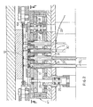
- the relative apparatus for carrying out the above specified process comprises a series of means to simultaneously grip and supply a plurality of microcomponents at preselected positions of a printed circuit board on which such microcerponents are to he applied, each of such means being actuated by a control member capable of gripping and releasing the microcomponent arranged at the top opening of each stack making up a magazine; a handling means to move said gripping means from a position substantially corresponding to the free top opening of the microconponent stack to another position substantially corresponding to the application position for said microconponent on said printed circuit board; and a means to feed said microcomponents along the magazine making up stacks, so as to enable the gradual withdrawal thereof.
- each of the gripping means comprise a pliers having two sliding resilient legs and that the control member to open and close each gripping means comprises a resilient cam guide which, in turn, is actuated by a wedge-shaped plate, the displacement of which varies the position of said cam guide, within which the gripping means slide.
- resilieot hook means are also provided, which hold the microcomponent arranged immediately beneath the component located at the free top opening of the microcomponent magazine, thus avoiding that the withdrawn microcomponent adheres to the adjacent microcomponent.
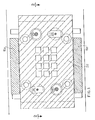
- the apparatus according to the invention comprises a series of magazines containing stacks 10 of microcomponents which are parallel to one another.
- the magazines are twelve, but actually the number will generally be of some thousands.
- the movement of plate 14 is caused, for example as shown in Figs. 1 and 2, by a pneumatic cylinder 28 having a stem 29 connected to said moving plate 14.
- the microcomponent magazine opens toward the printed circuit hoard 20 with a top opening 15, which may he at least partially closed by a stop device 16, normally of grate-like configuration, as shown in Fig. 2, wherein the several stop devices 16 are secured to a support member 16A.
- a stop grate normally of grate-like configuration
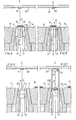
- pliers 12 are caused to re-enter within the cam guide 13. This can be readily done, see Fig. 9, since said cam guide 13 is now at open position.
- the step at which the microcomponent 11 is gripped by pliers 12 could be simultaneous with the displacement step of the stop grate, so as to clear the top opening 15.
- the return step of the pliers 12 to the gripping zone could be simultaneous with the closing step of the top opening 15.
- Figs. 11, 12 and 13 a secjional view is shown as taken perpendicularly to the sectional view shown in Figs. 4 through 10.
- the microcomponents in the respective magazines are here shown as arranged at 90° with respect to the position shown in Figs. 4 through 10.
- resilient members 17 providing hooking means 17a at the ends thereof, which can hold the microcomponent 21 arranged immediately beneath the end microcomponent which is driven by the gripping means.
- these resilient members 17 are pushed thanks to the action exerted to the supply end 31 of the microcomponent magazine 10, such members open, as shown in Fig. 12, so that a microcomponent designated by reference numeral 11 is enable to exit.
- the feeding movement of the components in the relative magazines can be given by movable push rods 30 reciprocating through a differentiated adjustable stroke, so as to take into account the different thicknesses of the components. Since the stop grate 16 is provided at such a position as to close the top opening 15, each of the components will be surely pushed to the correct position, so as to contact said stop grate 16.
- the push rods 30 may be introduced into the lower end of furhter magazines 32 arranged on the extension of the magazines from which the withdrawal is carried out. In this way it is possible to feed to the supply end 31 of magazines 10 a new microcomponents carried on a tape 33. This has been shown at the right side of Fig. 2, whereas the approach formerly described has been shown at the left side of the same figure. Of course, the components could be also supplied by a positioner feeder.
- the microcompcnents feeding takes place on passing from the step shown in Fig. 10 to the step shown in Fig. 4.
Landscapes
- Engineering & Computer Science (AREA)
- Manufacturing & Machinery (AREA)
- Microelectronics & Electronic Packaging (AREA)
- Supply And Installment Of Electrical Components (AREA)
Applications Claiming Priority (2)
| Application Number | Priority Date | Filing Date | Title |
|---|---|---|---|
| IT23591/80A IT1193954B (it) | 1980-07-22 | 1980-07-22 | Procedimento ed apparecchiatura atti a realizzare il montaggio su circuiti stampati di componenti sotto forma di "chip" |
| IT2359180 | 1980-07-22 |
Publications (1)
| Publication Number | Publication Date |
|---|---|
| EP0044496A1 true EP0044496A1 (fr) | 1982-01-27 |
Family
ID=11208389
Family Applications (1)
| Application Number | Title | Priority Date | Filing Date |
|---|---|---|---|
| EP81105455A Withdrawn EP0044496A1 (fr) | 1980-07-22 | 1981-07-13 | Procédé et appareillage pour l'assemblage de plaquettes à circuits imprimés avec des micro-composants électriques |
Country Status (3)
| Country | Link |
|---|---|
| EP (1) | EP0044496A1 (fr) |
| JP (1) | JPS5745994A (fr) |
| IT (1) | IT1193954B (fr) |
Cited By (1)
| Publication number | Priority date | Publication date | Assignee | Title |
|---|---|---|---|---|
| KR100727304B1 (ko) * | 2000-11-24 | 2007-06-12 | 엘지전자 주식회사 | 전계방출표시소자의 구동방법 |
Citations (1)
| Publication number | Priority date | Publication date | Assignee | Title |
|---|---|---|---|---|
| DE2716330A1 (de) * | 1976-04-12 | 1977-12-08 | Matsushita Electric Ind Co Ltd | Verfahren zur bestueckung von schaltungsplatinen mit plaettchenfoermigen schaltungsbauteilen und vorrichtung zur durchfuehrung desselben |
-
1980
- 1980-07-22 IT IT23591/80A patent/IT1193954B/it active
-
1981
- 1981-07-13 EP EP81105455A patent/EP0044496A1/fr not_active Withdrawn
- 1981-07-22 JP JP56115010A patent/JPS5745994A/ja active Pending
Patent Citations (1)
| Publication number | Priority date | Publication date | Assignee | Title |
|---|---|---|---|---|
| DE2716330A1 (de) * | 1976-04-12 | 1977-12-08 | Matsushita Electric Ind Co Ltd | Verfahren zur bestueckung von schaltungsplatinen mit plaettchenfoermigen schaltungsbauteilen und vorrichtung zur durchfuehrung desselben |
Cited By (1)
| Publication number | Priority date | Publication date | Assignee | Title |
|---|---|---|---|---|
| KR100727304B1 (ko) * | 2000-11-24 | 2007-06-12 | 엘지전자 주식회사 | 전계방출표시소자의 구동방법 |
Also Published As
| Publication number | Publication date |
|---|---|
| IT8023591A0 (it) | 1980-07-22 |
| IT1193954B (it) | 1988-08-31 |
| JPS5745994A (en) | 1982-03-16 |
Similar Documents
| Publication | Publication Date | Title |
|---|---|---|
| US4329776A (en) | Component inserting apparatus | |
| US4386464A (en) | Method and apparatus for mounting electronic components in position on circuit boards | |
| US4819699A (en) | Cartridge feed system for automatic PCB loading machine | |
| EP0071302B1 (fr) | Procédé et dispositif pour dispenser des composants électriques et/ou électroniques dans des positions données | |
| US4528747A (en) | Method and apparatus for mounting multilead components on a circuit board | |
| DE2858098C2 (de) | Vorrichtung zum Aufbringen von rechteckigen oder länglichen Chips auf eine Leiterplatte | |
| US5639203A (en) | Semiconductor device transfer apparatus | |
| US4616414A (en) | Method and apparatus for gripping multilead articles | |
| JPS6238876B2 (fr) | ||
| US4598471A (en) | Pin inserter for electronic boards | |
| US4125137A (en) | Apparatus for locating wires in predetermined co-planar relationship to each other | |
| US3669309A (en) | Machines for sequencing electronic components | |
| EP1326488B1 (fr) | Appareil d'alimentation en contacts sur banderole | |
| JP3771310B2 (ja) | フィーダー装置 | |
| US4628594A (en) | Electronic circuit element insertion apparatus | |
| EP0001891A1 (fr) | Appareil destiné à insérer des fils dans des bornes électriques | |
| US4389272A (en) | Process and feeding device to provide consecutive series of small objects on a single plane | |
| US4375719A (en) | Apparatus for assembling apertured members onto an array of terminal pins | |
| JP3781799B2 (ja) | 表面実装端子の連続ストリップをピックアンドプレース機械に供給するフィーダおよび供給方法。 | |
| US4069579A (en) | Method for inserting radial lead electronic components | |
| US4149641A (en) | Component feed mechanism | |
| US3576063A (en) | Bobbin lugger and method | |
| US3492713A (en) | Apparatus and method for forming and positioning | |
| EP0044519A1 (fr) | Procédé et appareillage pour l'assemblage de plaquettes à circuits imprimés avec des micro-composants électriques | |
| US5319847A (en) | Method and apparatus for conditioning leads of packaged electronic devices |
Legal Events
| Date | Code | Title | Description |
|---|---|---|---|
| PUAI | Public reference made under article 153(3) epc to a published international application that has entered the european phase |
Free format text: ORIGINAL CODE: 0009012 |
|
| AK | Designated contracting states |
Designated state(s): AT CH DE FR GB NL SE |
|
| STAA | Information on the status of an ep patent application or granted ep patent |
Free format text: STATUS: THE APPLICATION IS DEEMED TO BE WITHDRAWN |
|
| 18D | Application deemed to be withdrawn |
Effective date: 19830103 |
|
| RIN1 | Information on inventor provided before grant (corrected) |
Inventor name: FERRI, BENIAMINO Inventor name: CAIMI, GIOVANNI |