EP0044548B1 - Gelenkter Industrieroboter - Google Patents
Gelenkter Industrieroboter Download PDFInfo
- Publication number
- EP0044548B1 EP0044548B1 EP81105693A EP81105693A EP0044548B1 EP 0044548 B1 EP0044548 B1 EP 0044548B1 EP 81105693 A EP81105693 A EP 81105693A EP 81105693 A EP81105693 A EP 81105693A EP 0044548 B1 EP0044548 B1 EP 0044548B1
- Authority
- EP
- European Patent Office
- Prior art keywords
- forearm
- wrist
- industrial robot
- around
- reduction gear
- Prior art date
- Legal status (The legal status is an assumption and is not a legal conclusion. Google has not performed a legal analysis and makes no representation as to the accuracy of the status listed.)
- Expired
Links
Images



Classifications
-
- B—PERFORMING OPERATIONS; TRANSPORTING
- B25—HAND TOOLS; PORTABLE POWER-DRIVEN TOOLS; MANIPULATORS
- B25J—MANIPULATORS; CHAMBERS PROVIDED WITH MANIPULATION DEVICES
- B25J17/00—Joints
- B25J17/02—Wrist joints
- B25J17/0283—Three-dimensional joints
-
- B—PERFORMING OPERATIONS; TRANSPORTING
- B25—HAND TOOLS; PORTABLE POWER-DRIVEN TOOLS; MANIPULATORS
- B25J—MANIPULATORS; CHAMBERS PROVIDED WITH MANIPULATION DEVICES
- B25J9/00—Program-controlled manipulators
- B25J9/02—Program-controlled manipulators characterised by movement of the arms, e.g. cartesian coordinate type
- B25J9/04—Program-controlled manipulators characterised by movement of the arms, e.g. cartesian coordinate type by rotating at least one arm, excluding the head movement itself, e.g. cylindrical coordinate type or polar coordinate type
- B25J9/046—Revolute coordinate type
-
- B—PERFORMING OPERATIONS; TRANSPORTING
- B25—HAND TOOLS; PORTABLE POWER-DRIVEN TOOLS; MANIPULATORS
- B25J—MANIPULATORS; CHAMBERS PROVIDED WITH MANIPULATION DEVICES
- B25J9/00—Program-controlled manipulators
- B25J9/10—Program-controlled manipulators characterised by positioning means for manipulator elements
- B25J9/102—Gears specially adapted therefor, e.g. reduction gears
- B25J9/1025—Harmonic drives
-
- B—PERFORMING OPERATIONS; TRANSPORTING
- B25—HAND TOOLS; PORTABLE POWER-DRIVEN TOOLS; MANIPULATORS
- B25J—MANIPULATORS; CHAMBERS PROVIDED WITH MANIPULATION DEVICES
- B25J9/00—Program-controlled manipulators
- B25J9/10—Program-controlled manipulators characterised by positioning means for manipulator elements
- B25J9/106—Program-controlled manipulators characterised by positioning means for manipulator elements with articulated links
Definitions
- the present invention relates to an articulated industrial robot according to the first portion of claim 1.
- a supporting post is constituted by a turret which is rotatably mounted on a base and drivingly connected to a rotary driving means.
- a pair of parallel upper arms is pivotally mounted on the both outsides of the turret and drivingly connected to a driving means which is disposed together with the driving means for the other movable parts in the turret.
- a forearm is pivotally mounted and driven by a linear driving motor without interposing a reduction gear.
- the forearm is carrying a wrist, rotatably around its longitudinal axis and pivotally around a horizontal axis.
- Another industrial manipulator of the articulated type known from the US ⁇ A ⁇ 2861 699 is especially constructed for using in nuclear plants or for other dangerous purposes, in which the control operations take place by a locally separated control device.
- This manipulator has a support running on rails in a horizontal direction and an upper arm, a forearm and a wrist with a gripping tool.
- the arms and the wrist driving means are disposed in the support and drivingly connected by chains to spockets on the ends of these arms.
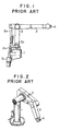
- FIG. 1 shows a known articulated industrial robot which has a working arm constituted by an upper arm 2 and a forearm 3.
- a driving source 3c for driving, through a feed screw mechanism, parallel links 3a, 3b connected to the forearm 3 is secured to a support 1 such as a turret for rotatably supporting the upper arm 2.
- a driving source for a feed screw mechanism for actuating a lever 2a unitarily connected to the upper arm 2 is secured to the support 1, but it is hidden behind the driving source 3c and not shown in this Figure.
- the arrangement is such that the power from the power source is converted into the movement of the forearm through the action of the link mechanism and feed screw mechanisms.
- Fig. 2 shows another type of known articulated industrial robot.
- This type of industrial robot has a forearm 3 adapted to be driven by a driving source which is secured to an upper arm 2, in such a manner that the forearm 3 is moved relatively to the upper arm 2.
- the later-mentioned type of known articulated industrial robot has an advantage that the mechanical restriction to the stroke or range of operation is small to afford a large stroke or range of operation over the first-mentioned type of known articulated industrial robot.
- a wrist 4 having at least one degree of freedom is secured to the end of the forearm 3 of each of the robots explained heretofore.
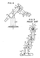
- the driving source and the driving system for the upper arm 2, the forearm 3 and the wrist 4 are arranged, for example, in a manner shown in Fig. 3.
- the upper arm 2 is supported at its one end rotatably by the rotary support 1 through the medium of a bearing 18.
- a driving source 6 such as a D.C. servo motor for driving the upper arm 2 is secured to the rotary support 1.
- the torque of the driving source 6 is transmitted to a reduction gear 9 such as a harmonic reduction gear through a rotary shaft 7 and a pair of bevel gears 8,8', and the output side of this reduction gear 9 is connected to the upper arm 2.
- the forearm 3 is rotatably secured to the other end of the upper arm 2 through a bearing 19.
- a driving source 10 such as a D.C. servo motor for driving the forearm 3 is attached to the upper arm 2.
- the torque of this driving source 10 is transmitted to a reduction gear fixed to the upper arm 2, through a rotary shaft 11 and a pair of bevel gears 12, 12'.
- the output side of the reduction gear 13 is connected to the forearm 3.
- the wrist 4 is rotatably secured to the end of the wrist 3 through bearings 20, 20', and is adapted to be driven by a driving source 14 such a D.C. servo motor attached to the forearm 3.
- the torque of this driving source is transmitted, through a rotary shaft 15 and a pair of bevel gears 16, 16', to a reduction gear 17 such as a harmonic reduction gear 17 the output shaft of which is connected to the wrist 4, thereby to drive the latter.
- a reduction gear 17 such as a harmonic reduction gear 17 the output shaft of which is connected to the wrist 4, thereby to drive the latter.
- the wrist4 is shown in Fig. 3 to have only one degree of freedom, i.e. the rotation around an axis A-A'
- the wrist 4 in ordinary articulated industrial robot has two or more degrees of freedom including a rotation around an axis B or a rotation or pivoting around a point C (shown by arrow C') in combination.
- the driving source 10 for driving the forearm 3 is secured to the upper arm 2
- the driving source for achieving each of the above-mentioned degree of freedom is secured to the forearm 3 as in the case of the driving source 14 shown in the drawing, and achieves rotary motion around its own axis of rotation by making use of a differential gear mechanism.
- the forearm 3 and the wrist 4 are driven independently relatively to the upper arm 2 and the forearm 3, respectively, and the positions or postures of the forearm 3 and the wrist 4 are controlled through the control of their positions relative to the upper arm 2 and the forearm 3, respectively.
- the posture of the wrist 4 is affected by the postures of the upper arm 2 and the forearm 3. Therefore, in order to move the wrist 4 while maintaining the latter in a predetermined relation to an absolute reference plane such as floor surface, platform orthe like, it is necessary to effect the control of the wrist4 in such a manner as to compensate for the change of postures of the upper arm 2 and the forearm 3.
- the known articulated robots incorporate a plurality of driving sources for imparting to the wrist a plurality of degrees of freedom, as well as differential gear systems, the change in the degree of freedom of the wrist 4 cannot be achieved without being accompanied by a large scale of modification including the modification of construction of the forearm 3 itself. It is, therefore, extremely difficult to easily change the combination of degrees of freedom to meet various requirements or expected robot tasks.
- the object of the invention is to provide an articulated industrial robot which permits an easy and accurate control of posture of the wrist relative to the ground regardless of the posture of the arms.
- the articulated industrial robot can have an adaptability to both demands of control of the posture of the wrist and holding the wrist in a constant posture, the change between these two modes can easily be attained simply by changing one of the upper arms. It is also to be noted that, according to the invention, it is possible to obtain an additional degree of freedom by constructing the supporting post with a turret which is rotatably supported to a rotation driving source which in turn is mounted on the base, so that it becomes possible to transport an article over a long distance to process or assemble the article.
- rotary driving sources for controlling the posture of the wrist and other purposes while the connecting mechanism for upper arm, connecting mechanism for forearm and the wrist posture connecting mechanism are constituted only by rotary parts such as rotary shafts and bevel gears, and the reduction gears are provided at the portion of the system near the output end.
- the power loss in the transmission system is reduced and the connecting mechanisms are standardized and simplified to permit a remarkable reduction of the production cost of the articulated industrial robot.
- Fig. 4 is an outside view of an articulated industrial robot in accordance with an embodiment of the invention.
- This articulated industrial robot has a base 21, a turret 22, upper arms 23, 23', forearm 24 and a wrist 26.
- the robot of this embodiment has 6 (six) kinds of degrees of freedom: namely a rotation around a Z axis, rotation of upper arms 23, 23' around Y' axis, rotation of forearm 24 around V 2 axis, rotation of lower half part 25 of forearm around the X' axis, rotation of wrist 26 around y3 axis, and rotation of tool mount 27 around the X 2 axis.
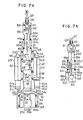
- Fig. 5a illustrates the driving system for each motion, in the state in which the upper arm 23 and the forearm 24 of the robot shown in Fig. 4 are stretched
- Fig. 5b is a sectional view taken along the line X-X' of Fig. 5a.
- a turret 22 is rotatably supported by the base 21 through rotary bearings 33, 33', and the output shaft 30 of a rotary drive source 29a (such as a D.C. servo motor) fixed to the base 21 is connected to a reduction gear 32 (such as a harmonic reduction gear) fixed to the base 21, via a safety brake 31 (such as solenoid brake of energize to off type) which is also fixed to the base 21.
- a rotary drive source 29a such as a D.C. servo motor
- a reduction gear 32 such as a harmonic reduction gear
- a safety brake 31 such as solenoid brake of energize to off type
- the low-speed side i.e. the output side of the reduction gear 32 is fixed to the turret 22, so that the rotary drive source 29a imparts to the turret 22 a rotation around the Z axis as shown in Figs. 4 and 5a.
- a rotary driving source (such as D.C. servo motor) for driving the upper arm 23 is mounted in the turret 22.
- the output shaft 35 of the rotary driving source is connected, through the safety brake 36 and via a pair of bevel gears 37, 37', to a reduction gear 38 fixed to an upper part of the turret 22.
- the pair of upper arms 23, 23' are rotatably secured to an upper portion of the turret 22 through respective rotary bearings, 39, 39'.
- the low speed output of the reduction gear 38 is connected to one 23 of the upper rams so that the rotary driving source 34 imparts to the upper arms 23, 23' the rotation around the Y' axis shown in Fig. 5a.
- a rotary driving source 40a (such as a D.C. servo motor) for driving the forearm 24 is attached to the rear end of the upper arm 23.
- the output shaft 42 of the driving source 40a is connected, through a safety brake 41 and a pair of bevel gears 43, 43', to a reduction gear 44 fixed to the end of the upper arm 23.
- the rotary driving source 40a attached to the rear end of the upper arm 23 imparts to the upper half part 25a of the forearm the rotation around the y2 axis as shown in Figs. 4 and 5.
- a gear 47 is attached to the output shaft of a rotary driving source (such as D.C. servo motor) fixed to the upper half part 25a of the forearm.
- Another gear 48 is fixed to the input shaft of a reduction gear 50 which is fixed to the upper half part 25a and having a low speed output connected to the lower half part 25b of the forearm.
- the driving system constituted by the rotary driving source 40a for driving the upper half part 25a of the forearm, output shaft 42, bevel gears 43, 43' and so forth is mounted only on one 23 of the two upper arms 23, 23'.
- a rotary driving source 51a (such as D.C. servo motor) for driving the wrist 26.
- the output shaft 52 of this rotary driving source 51 a is introduced through a pair of bevel gears 53, 53; into the upper half part 25a and further to the end portion of the lower half part 25b of the forearm through another pair of bevel gears 54, 54' and the rotary shaft 55.
- the wrist 26 is rotatably secured to the lower half part 25b of the forearm through a rotary bearing 58.
- a reduction gear 57 fixed to the lower half part 25b has a low-speed output coupled to the wrist 26.
- the rotary shaft 55 is connected at its end to the input shaft of the reduction gear 57 through bevel gears 56, 56', so that the rotary driving source 51a fixed to the rear end of the upper arm 23' imparts to the wrist 26 a rotation around the Y 3 axis as shown in Fig. 4 and 5a.
- the transmission of power at the inside of the forearm 24 is achieved by a rotary shaft 55 which is coaxial with the axis of rotation of the lower half part 25b of the forearm and extending through a cavity or bore formed in the gear 48 and the reduction gear 50 for driving the lower half part 25b of the lower half part 25b. Therefore, the rotary motion of the lower half part 25b can be achieved without substantially hindering the operation of the driving system.
- a rotary driving source 59a (such as D.C. servo motor) is mounted on the wrist 26 and has an output shaft 60 connected to the input shaft of the reduction gear 61 fixed to the wrist 26.
- the low-speed output of the reduction gear 61 is connected to the tool mount 27 which is rotatably supported by the wrist 26 through rotary bearings 62, 62', so as to impart to the tool mount 27 the rotation around the X 2 axis as shown in Figs. 4 and 5a.
- the articulated industrial robot in which the kinds of degree of freedom can easily be varied to suit for various user's demands through a minor change without necessitating the change of construction of the arms and driving system.
- the articulated industrial robot can function to hold the wrist 26 in a constant posture with respect to the turret 22 or to an external object, so that the driving sources, reduction gears and corresponding controllers can be eliminated and saved when the robot is required only to suit for the simple works to permit the production of robots at low cost using common major constituents or parts.
- controlling system for controlling the wrist 26 and the tool mount (or work mount) 27 are completely separated from each other, and the tool mount 27 can be mounted on the wrist 26.
- the wrist mechanism shown in Fig. 6a is the one explained before in connection with Figs. 5a and 5b.
- This wrist mechanism accommodates the driving source 59 and reduction gear 61 for rotatively driving the tool mount 27 independently of the body of the wrist 26.
- the wrist 26 shown in Fig. 6b does not accommodate any mechanism and the tool mount 27 is fixed to the end of the wrist 26.
- the tool mount 27 is fixed to the body of the wrist 26 which carries a driving source 70 for the tool, such as a D.C. motor or a pneumatic cylinder.
- the output shaft 71 of the driving source 70 is exposed to the outside of the tool mount 27.
- the users can actuate various tools meeting the demands such as a gripper 72, thus reducing the size and weight of the tool 72 as compared with the case where the tool 72 itself carries the driving source.
- the tool 72 is a gripper constituted by a pair of fingers 73, 73' which are rotatably secured to the base 75 by means of pivots 74, 74'.
- the fingers 73, 73' are pivotally secured at their one ends through link members 76, 76' to an input link 77 fixed to a nut 79 which is adapted to be fed linearly by means of a ball screw 78 connected to the output shaft 71 through a coupling 80. It is, therefore, possible to move the fingers 73, 73' toward and away from each other by the driving source incorporated in the wrist 26.
- the driving source 59 for the tool mount 27 and the driving source 70 for the toll 72 are commonly accommodated in the wrist 26.
- the output shaft 71 of the driving source 70 is extended through the cavities or bores formed in the tool mount 27 and the reduction gear 81.
- a gear 81 is fixed to the output shaft of the tool mount driving source 59 and meshes with a hollow gear 82 which is connected to the input shaft of the hollow reduction gear 83 thereby to rotatively drive the tool mount 27.
- the example of the tool shown in Fig. 6d is identical to that shown in Fig. 6c.
- the system for driving and controlling the wrist 26 is constructed independently from the system for driving the tool mount 27 which is provided at the end of the wrist 26, and the driving source 59 for the tool mount is carried by the wrist 26. It is, therefore, possible to select freely the wrist having various functions as shown in Figs. 6a to 6d, without necessitating substantial change in the body of the robot starting from the base 21 to the end of the lower half part 25 of the forearm.
- the forearm 24 in the above-described robot is omitted, and any one of the wrists mentioned above having various functions can be rotatably secured to the ends of the upper arms 23,23' through a bearing.
- the posture of the wrist 26 is controlled by means of the forearm driving system 40, 42, 43, 43', 44 shown in Fig. 5.
- This arrangement permits an easy production of robots suited for the desired simple work, using equivalent major parts to those of the robot shown in Fig. 5.
- Figs. 7a and 7b show a different embodiment in which the forearm 24 of the articulated industrial robot shown in Figs. 5a and 5b is substituted by a stretchable forearm 24a intended for assembling or processing of a work or article by conveying the latter detouring above or around any obstruction around the industrial articulated robot.
- the forearm 24a includes an upper half part 25a' rotatably connected to the ends of the upper arms 23, 23' through bearings 45, 45', a lower half part 25b' slidably supported through linear bearings 49, 49' by the free end of the upper half part 25'a and carrying a wrist 26 for rotations around the Y 3 and X 2 axes, an upper half part 55a of a rotary shaft carrying at its one end a bevel gear 54' and provided at its other end with a spline shaft 90, a lower half part 55b of the rotary shaft provided at its one end with the spline boss 91 for engaging the spline shaft 90 and at its other end with a bevel gear 56, a rotary driving source (such as a D.C.
- a rotary driving source such as a D.C.
- servo motor 92a mounted on the upper half part 25a', a gear 93 fixed to the output shaft of the rotary driving source 92a, a lead screw 95 having a gear 94 fixed thereto and meshing with the gear 93 and rotatably supported by the upper half part 25a', and a nut 96 secured to the lower half part 25b' and meshing with the lead screw 95.
- gear 93 fixed to the output shaft of the rotary driving source 92a
- lead screw 95 having a gear 94 fixed thereto and meshing with the gear 93 and rotatably supported by the upper half part 25a'
- a nut 96 secured to the lower half part 25b' and meshing with the lead screw 95.
- the lead screw 95 is rotated to extend and retract the lower half parts 25b' of the upper arm relatively to the upper half part 25a', i.e. to stretch the forearm 24a.
- This arrangement permits a processing of a work situated at a comparatively remote place by the tool held by the tool mount 27, detouring above or around any obstruction residing between the robot and the work, or to assemble a part carried by the hand 27 on an assembly detouring above or around the obstruction.
- the articulated industrial robot is required to move in synchronization with the movement of articles conveyed by a conveyor or the like (not shown) to effect a processing or assembling.
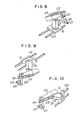
- any type of the industrial robot heretofore described can be mounted on a carriage or truck adapted to run along a truck 100 laid on the floor (See Fig. 8), truck 101 suspended from the ceiling (See Fig. 9) or a track hung from vertical wall (See Fig. 10), by the power from the driving source (not shown) such as a motor mounted along the track 100, 101, 102.
- the driving source 40a for driving the forearm 24 is attached to the rear end of the upper arm 23, while the rotary driving source 51 for the wrist 26 is secured to the rear end of the upper arm 23'.
- These driving sources transmit the driving power through their output shafts 42, 52 and respective pairs of bevel gears 43,43'; 53, 53'.
- This arrangement is not essential, and can be substituted by an equivalent arrangement a typical one of which is shown in Fig. 11. More specifically, in the arrangement shown in Fig. 11, the rotary driving source 40a for the forearm 24 is attached to one side of the upper arm 23.
- the output shaft 120 is extended through a safety brake 41.
- a belt pulley or a sprocket wheel 121 is attached to this output shaft 121.
- a belt pulley or sprocket wheel 123 is attached to the input shaft of the reduction gear 44.
- the driving power is transmitted through a timing belt or a chain 124 stretched between the pulleys or sprocket wheels 121 and 123.
- the driving power is transmitted through a timing belt or a chain 128 stretched between a belt pulley of sprocket wheel 126 fixed to the output shaft 125 of a wrist driving source 51 a fixed to the side surface of the upper arm 23' and a belt pulley or sprocket wheel 127 fixed to the input shaft 53' connected to the bevel gear 54.
- the output shaft 125 may be fixed to the supporting post 22 as shown in Fig. 16.
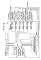
- the controller 110 includes a microprocessor unit 113 adapted for making arithmetic control of operation of the rotary driving sources 29a, 34a, 40a, 51a, 46a (92a), 59a, a write-on memory (ROM) 111 storing operation program, D/A converters 114a to 114f for converting digital signals into analog signals, D.C. servo amplifiers 115a to 115f for driving respective D.C.
- ROM write-on memory
- a reference numeral 118 denotes a teaching box, while 119 denotes a central controller or a peripheral equipment for giving instructions such as a starting instruction.
- the microprocessing unit 113 reads out the program stored in the ROM 111, and makes a processing using the operation unit 116 and the function table 117 to produce suitable signal for making the hand of the robot follow the predetermined locus, from the data concerning the present position in the spherical coordinate derived from the counters 112a to 112f.
- the thus obtained signal in the form of a digital signal is then delivered to the D/A converters 114a to 114f which in turn deliver alanol signals to D.C. servo amplifiers 115a to 115f.
- the amplifiers then drive respective D.C. motors 29a, 34a, 40a, 51a, 46a (92a), 59a to permit the articulated industrial robot to perform the desired task.
- the tacho- generators 29b, 34b, 40b, 51 b, 46b (92b), 59b are provided for feeding back the speeds of D.C. motors 29a, 34a, 40a, 51a, 46a (92a), 59a to the D.C. servo amplifiers 115a to 115f to effect the speed control of these motors.
- an articulated industrial robot comprising a base, a supporting post provided on the base, a forearm provided at its end with a wrist having at least one degree of freedom, and a pair of upper arms pivotally connected at their one ends to the supporting post and at their other ends to the forearms, the upper arms being arranged at both sides of the supporting post and the forearm.
- the rotary driving sources such as D.C. servo motors are used as the driving sources of the upper arms, forearm and wrist, while transmitting mechanisms such as upper arm connecting mechanism, forearm mechanism, and wrist posture connecting mechanism are constituted by rotary transmission members such as rotary shafts, gears (bevel gears) and so forth, with the reduction gears provided near the output ends of respective transmission systems.
- the power is transmitted with much reduced loss, and the construction of the transmission systems is very much simplified to achieve a remarkable reduction in the production cost.
- the forearm is constituted by an upper half part and a lower half part which is rotatable relatively to the upper half part around the longitudinal axis and extendable and retractable in the longitudinal direction, to impart a rotational and stretching functions to the forearm. It is, therefore, possible to move the tool or a part carried by the hand detouring peripheral obstructions from all directions to effect mechanical processing or assembling on an object spaced by the robot by the obstruction or to effect a processing or assembling on an object remote from the robot detouring above the peripheral obstruction.
Landscapes
- Engineering & Computer Science (AREA)
- Robotics (AREA)
- Mechanical Engineering (AREA)
- Manipulator (AREA)
Claims (8)
dadurch gekennzeichnet,
Applications Claiming Priority (2)
| Application Number | Priority Date | Filing Date | Title |
|---|---|---|---|
| JP9875980A JPS5727686A (en) | 1980-07-21 | 1980-07-21 | Industrial articular robot |
| JP98759/80 | 1980-07-21 |
Publications (2)
| Publication Number | Publication Date |
|---|---|
| EP0044548A1 EP0044548A1 (de) | 1982-01-27 |
| EP0044548B1 true EP0044548B1 (de) | 1986-10-15 |
Family
ID=14228346
Family Applications (1)
| Application Number | Title | Priority Date | Filing Date |
|---|---|---|---|
| EP81105693A Expired EP0044548B1 (de) | 1980-07-21 | 1981-07-20 | Gelenkter Industrieroboter |
Country Status (4)
| Country | Link |
|---|---|
| US (1) | US4507046A (de) |
| EP (1) | EP0044548B1 (de) |
| JP (1) | JPS5727686A (de) |
| DE (1) | DE3175464D1 (de) |
Families Citing this family (70)
| Publication number | Priority date | Publication date | Assignee | Title |
|---|---|---|---|---|
| JPS6114889A (ja) * | 1984-06-29 | 1986-01-23 | フアナツク株式会社 | 内圧防爆構造の電動式産業用ロボツト |
| JPS5727686A (en) * | 1980-07-21 | 1982-02-15 | Hitachi Ltd | Industrial articular robot |
| DE3048067C2 (de) * | 1980-12-19 | 1984-08-09 | Kuka Schweissanlagen + Roboter Gmbh, 8900 Augsburg | Getriebeanordnung für den Gelenkkopf eines Manipulators |
| FR2512727A1 (fr) * | 1981-09-15 | 1983-03-18 | Renault | Poignet orientable a trois axes de rotation pour robot industriel |
| US4921395A (en) * | 1982-04-16 | 1990-05-01 | Sahlin International, Inc. | Apparatus for loading and/or unloading industrial presses |
| US5017083A (en) * | 1982-04-16 | 1991-05-21 | Sahlin International, Inc. | Apparatus for loading and/or unloading industrial presses |
| DE3228945A1 (de) * | 1982-08-03 | 1984-02-16 | GdA Gesellschaft für digitale Automation mbH, 8000 München | Vorrichtung zum antrieb der beiden achsen des handgliedes eines industrieroboters |
| US4624621A (en) * | 1982-10-21 | 1986-11-25 | Kabushiki Kaisha Kobe Seiko Sho | Wrist mechanism for industrial robots and the like |
| FR2539346B1 (fr) * | 1983-01-18 | 1990-12-07 | Mitsubishi Electric Corp | Dispositif manipulateur automatique articule notamment pour le soudage a l'arc |
| GB2139593B (en) * | 1983-03-10 | 1986-03-26 | Mitsubishi Electric Corp | Industrial robot |
| GB8327937D0 (en) * | 1983-10-19 | 1983-11-23 | Colne Robotics Co Ltd | Mechanical handling apparatus |
| GB2149707B (en) * | 1983-11-15 | 1987-10-28 | Hitachi Shipbuilding Eng Co | Automatic welding apparatus |
| JPS60127989A (ja) * | 1983-12-14 | 1985-07-08 | ファナック株式会社 | 産業用ロボットの手首駆動機構 |
| JPS60135196A (ja) * | 1983-12-22 | 1985-07-18 | 株式会社安川電機 | 産業用ロボツトの手首機構 |
| WO1985003024A1 (fr) * | 1984-01-13 | 1985-07-18 | Mitsubishi Denki Kabushiki Kaisha | Dispositif de poignet pour robot industriel |
| DE3513056A1 (de) * | 1984-04-18 | 1985-10-24 | GCA Corp., Bedford, Mass. | Gelenk-antriebsanordnung |
| US4574655A (en) * | 1984-07-16 | 1986-03-11 | Kabushiki Kaisha Yasakawa Denki Seisakusho | Wrist mechanism for industrial robot |
| DE8430397U1 (de) * | 1984-10-16 | 1986-05-28 | Manutec Gesellschaft für Automatisierungs- und Handhabungssysteme mbH, 8510 Fürth | Robotergelenkmechanismus |
| JPS61109677A (ja) * | 1984-10-30 | 1986-05-28 | 株式会社安川電機 | 産業用ロボツトのア−ムバランス装置 |
| US4984745A (en) * | 1985-01-22 | 1991-01-15 | Gmf Robotics Corporation | Electric robot for use in a hazardous location |
| US6477913B1 (en) | 1985-01-22 | 2002-11-12 | Fanuc Robotics North America, Inc. | Electric robot for use in a hazardous location |
| JPS61214983A (ja) * | 1985-03-15 | 1986-09-24 | 三菱電機株式会社 | 産業用ロボツトの搬送装置 |
| DE8511948U1 (de) * | 1985-04-22 | 1985-07-11 | GdA Gesellschaft für digitale Automation mbH, 8000 München | Getriebeanordnung für eine Industrieroboterhand |
| IT1182515B (it) * | 1985-07-15 | 1987-10-05 | Imp Prima Spa | Dispositivo manipolatore particolarmente per il maneggio di lamiere durante operazioni di piegatura |
| US4683772A (en) * | 1985-07-25 | 1987-08-04 | Westinghouse Electric Corp. | Hand gear train with three degrees of freedom |
| DE8525812U1 (de) * | 1985-09-10 | 1987-02-19 | Manutec Gesellschaft für Automatisierungs- und Handhabungssysteme mbH, 8510 Fürth | Gelenkroboter |
| DE3545068A1 (de) * | 1985-12-19 | 1987-06-25 | Kuka Schweissanlagen & Roboter | Getriebekopf fuer manipulatoren |
| SE460529B (sv) * | 1986-02-18 | 1989-10-23 | Asea Ab | Industrirobot |
| JPS62287991A (ja) * | 1986-06-09 | 1987-12-14 | ファナック株式会社 | 産業用ロボツトの手首駆動機構 |
| SE453579B (sv) * | 1986-06-12 | 1988-02-15 | Asea Ab | Robothandled bestaende av tva handledshalvor |
| GB2198413B (en) * | 1986-11-20 | 1990-01-17 | Shimizu Construction Co Ltd | Transporting robot for semiconductor wafers |
| FR2620837B1 (fr) * | 1987-09-21 | 1990-11-30 | Commissariat Energie Atomique | Dispositif d'orientation d'un objet autour de deux axes de rotation |
| JP2591968B2 (ja) * | 1987-12-28 | 1997-03-19 | 株式会社日立製作所 | 産業用ロボットの手首 |
| SE466994B (sv) * | 1988-04-13 | 1992-05-11 | Asea Brown Boveri | Robothandled |
| US5037267A (en) * | 1988-06-17 | 1991-08-06 | Protomark Corporation | Load balancing mechanism |
| US5102280A (en) * | 1989-03-07 | 1992-04-07 | Ade Corporation | Robot prealigner |
| IT1241622B (it) * | 1990-10-04 | 1994-01-25 | Comau Spa | Polso di robot |
| IT1241621B (it) * | 1990-10-04 | 1994-01-25 | Comau Spa | Robot articolato |
| JP2572483B2 (ja) * | 1990-10-16 | 1997-01-16 | 本田技研工業株式会社 | 産業用ロボット装置 |
| IT1245512B (it) * | 1991-02-15 | 1994-09-29 | Comau Spa | Robot articolato dotato di doppio avambraccio |
| IT1245433B (it) * | 1991-03-04 | 1994-09-20 | Comau Spa | Polso di robot industriale |
| US5497674A (en) * | 1991-06-04 | 1996-03-12 | Kawasaki Jukogyo Kabushiki Kaisha | Industrial robot |
| US5245263A (en) * | 1991-09-13 | 1993-09-14 | University Of Maryland | Anti-backlash drive systems for multi-degree freedom devices |
| US5492443A (en) * | 1993-10-14 | 1996-02-20 | Leland D. Blatt | Apparatus for handling a workpiece between work stations |
| US5587637A (en) * | 1994-01-10 | 1996-12-24 | Tatsumo Kabushiki Kaisha | Robot arm device capable of conveying an article in circumferential and radial directions |
| DE10042991A1 (de) * | 2000-09-01 | 2002-03-21 | Mueller Weingarten Maschf | Gelenkarm-Transportsystem |
| WO2004103649A1 (ja) * | 2003-05-20 | 2004-12-02 | Fujitsu Limited | バックラッシュ補償制御方法、バックラッシュ補償制御装置およびバックラッシュ補償制御プログラム |
| JP2008023642A (ja) * | 2006-07-20 | 2008-02-07 | Fanuc Ltd | 産業用ロボットのアーム構造体 |
| DK1982799T3 (da) * | 2007-04-10 | 2010-08-16 | Erowa Ag | Håndteringsapparat |
| EP2164684B1 (de) * | 2007-05-14 | 2020-05-06 | Thermo CRS Ltd. | Automatisierter objektantrieb |
| CN102001095B (zh) * | 2009-09-03 | 2014-07-09 | 鸿富锦精密工业(深圳)有限公司 | 机器人臂部件及机器人 |
| CN102259337B (zh) * | 2010-05-28 | 2013-11-06 | 鸿富锦精密工业(深圳)有限公司 | 机器人臂部件 |
| WO2013142931A1 (pt) * | 2012-03-26 | 2013-10-03 | Moeller Lucas | Sistema de recapagem de pneus constituído por braço robotizado com movimentos de interpolação angular |
| US10307980B2 (en) * | 2013-02-20 | 2019-06-04 | The Goodyear Tire & Rubber Company | Tire building applicator members and systems |
| JP5702826B2 (ja) * | 2013-04-30 | 2015-04-15 | ファナック株式会社 | 産業用ロボットの手首構造 |
| JP6607661B2 (ja) * | 2013-08-09 | 2019-11-20 | 日本電産サンキョー株式会社 | 水平多関節ロボット |
| US20150068350A1 (en) * | 2013-09-10 | 2015-03-12 | Seiko Epson Corporation | Robot arm and robot |
| JP6337432B2 (ja) | 2013-09-10 | 2018-06-06 | セイコーエプソン株式会社 | 関節駆動装置及びロボット |
| CN106584424A (zh) * | 2015-10-14 | 2017-04-26 | 安徽赛耐尔机械制造有限公司 | 一种轮胎装框机械手 |
| US10011469B2 (en) * | 2016-04-12 | 2018-07-03 | General Electric Company | Rotatable engagement of additive manufacturing build plate |
| CN105883400B (zh) * | 2016-06-13 | 2018-06-15 | 广东溢达纺织有限公司 | 送纬辅助放纱设备及纬纱盘输送方法 |
| US10576644B2 (en) | 2017-03-31 | 2020-03-03 | Kinova Inc. | Articulated mechanism with internal brake assembly |
| CN107414817B (zh) * | 2017-07-04 | 2023-04-25 | 国网吉林省电力有限公司白山供电公司 | 一种拼插式六自由度关节型工业机器人 |
| US10109517B1 (en) * | 2018-01-10 | 2018-10-23 | Lam Research Corporation | Rotational indexer with additional rotational axes |
| CN108189002B (zh) * | 2018-01-23 | 2021-01-01 | 江苏铁锚玻璃股份有限公司 | 一种应用于恶劣工况的压电超声振子驱动型检修机械臂 |
| CN108044599B (zh) * | 2018-01-23 | 2020-12-15 | 台州技创机械科技有限公司 | 一种应用于强磁场强辐射工况的检修机械臂装置 |
| CN108161458A (zh) * | 2018-01-31 | 2018-06-15 | 杭州辉昂科技有限公司 | 一种超声波切割机器人 |
| CN108943011B (zh) * | 2018-07-16 | 2021-05-25 | 安徽智森电子科技有限公司 | 一种角度可调节的机械臂 |
| JP7469135B2 (ja) * | 2020-05-12 | 2024-04-16 | 川崎重工業株式会社 | 手首装置及びロボット |
| JP7587439B2 (ja) * | 2021-02-24 | 2024-11-20 | 株式会社ソニー・インタラクティブエンタテインメント | 回転装置 |
Family Cites Families (12)
| Publication number | Priority date | Publication date | Assignee | Title |
|---|---|---|---|---|
| US2861699A (en) * | 1950-10-16 | 1958-11-25 | Gen Mills Inc | Method and apparatus for performing operations at a remote point |
| US3247979A (en) * | 1962-12-14 | 1966-04-26 | Programmed & Remote System Cor | Manipulator control system |
| DE2225476C3 (de) * | 1972-05-25 | 1975-04-24 | Engel, Heinrich, 6407 Schlitz | Betätigungsvorrichtung |
| DE2226407C3 (de) * | 1972-05-31 | 1978-10-12 | Industrie-Werke Karlsruhe Augsburg Ag, 7500 Karlsruhe | Gerät zur maschinellen, durch veränderbare Programme steuerbaren Handreichung |
| JPS5425300B2 (de) * | 1973-01-25 | 1979-08-27 | ||
| US3985238A (en) * | 1973-03-17 | 1976-10-12 | Daikin Kogyo Co., Ltd. | Industrial robot |
| DE2330393C3 (de) * | 1973-06-15 | 1975-11-27 | Bruker-Physik Ag, 7501 Forchheim | Manipulator, insbesondere für Unterwasserfahrzeuge |
| US4275986A (en) * | 1975-10-28 | 1981-06-30 | Unimation, Inc. | Programmable automatic assembly system |
| GB1567100A (en) * | 1977-10-03 | 1980-05-08 | Caterpillar Tractor Co | Flow control assembly for multi-piston pumps |
| DE2861285D1 (en) * | 1977-10-20 | 1982-01-14 | Ici Plc | An industrial manipulator for placing articles in close proximity to adjacent articles and a method of close packing articles therewith |
| FR2483300A1 (fr) * | 1980-05-28 | 1981-12-04 | Expl Mat Indls Const | Manipulateur industriel perfectionne |
| JPS5727686A (en) * | 1980-07-21 | 1982-02-15 | Hitachi Ltd | Industrial articular robot |
-
1980
- 1980-07-21 JP JP9875980A patent/JPS5727686A/ja active Pending
-
1981
- 1981-07-20 DE DE8181105693T patent/DE3175464D1/de not_active Expired
- 1981-07-20 EP EP81105693A patent/EP0044548B1/de not_active Expired
- 1981-07-21 US US06/285,637 patent/US4507046A/en not_active Expired - Fee Related
Also Published As
| Publication number | Publication date |
|---|---|
| EP0044548A1 (de) | 1982-01-27 |
| DE3175464D1 (en) | 1986-11-20 |
| US4507046A (en) | 1985-03-26 |
| JPS5727686A (en) | 1982-02-15 |
Similar Documents
| Publication | Publication Date | Title |
|---|---|---|
| EP0044548A1 (de) | Gelenkter Industrieroboter | |
| KR102174924B1 (ko) | 회전운동 전달 메카니즘이 구비된 병렬로봇 | |
| EP0200105B1 (de) | Industrieroboter | |
| US4275986A (en) | Programmable automatic assembly system | |
| US4854808A (en) | Multi-articulated industrial robot with several degrees of freedom of movement | |
| US5006036A (en) | Portal system | |
| EP3784446B1 (de) | Parallelkinematikroboter | |
| CA2505108A1 (en) | Four-degree-of-freedom parallel manipulator for producing schonflies motions | |
| US4496278A (en) | Industrial robot equipped with articulated arm unit | |
| GB2125767A (en) | Industrial robot of the articulated type | |
| WO1990001403A1 (fr) | Robot articule horizontal | |
| KR102108674B1 (ko) | 회전운동 전달 메카니즘이 구비된 병렬로봇 | |
| EP0022332B1 (de) | Industrieroboter | |
| US4761114A (en) | Articulated head for an industrial robot and a robot equipped with a head of this type | |
| US5107719A (en) | Adjustable robotic mechanism | |
| JP2003535711A (ja) | 2つのパラレルブランチを有する制御アーム | |
| CN107249827A (zh) | 工业用机器人 | |
| USRE32794E (en) | Programmable automatic assembly system | |
| EP0052149A1 (de) | Flexible beschickungeinrichtung für eine werkzeugmaschine und verfahren zu deren verwendung | |
| EP0121576A1 (de) | Industrieller roboter vom gelenkten armtyp | |
| JPH11254357A (ja) | 水平アームを有するロボット | |
| KR100405808B1 (ko) | 6축 다관절 산업용 로봇의 상부암 구조 | |
| CN117381848B (zh) | 一种差动式低惯量机械臂 | |
| JP2694511B2 (ja) | 直交ロボットの手首軸 | |
| JPH11309684A (ja) | ハンドリングロボット |
Legal Events
| Date | Code | Title | Description |
|---|---|---|---|
| PUAI | Public reference made under article 153(3) epc to a published international application that has entered the european phase |
Free format text: ORIGINAL CODE: 0009012 |
|
| AK | Designated contracting states |
Designated state(s): DE FR GB IT SE |
|
| 17P | Request for examination filed |
Effective date: 19820521 |
|
| GRAA | (expected) grant |
Free format text: ORIGINAL CODE: 0009210 |
|
| AK | Designated contracting states |
Kind code of ref document: B1 Designated state(s): DE FR GB |
|
| REF | Corresponds to: |
Ref document number: 3175464 Country of ref document: DE Date of ref document: 19861120 |
|
| ET | Fr: translation filed | ||
| PLBE | No opposition filed within time limit |
Free format text: ORIGINAL CODE: 0009261 |
|
| STAA | Information on the status of an ep patent application or granted ep patent |
Free format text: STATUS: NO OPPOSITION FILED WITHIN TIME LIMIT |
|
| 26N | No opposition filed | ||
| PGFP | Annual fee paid to national office [announced via postgrant information from national office to epo] |
Ref country code: FR Payment date: 19890622 Year of fee payment: 9 |
|
| PGFP | Annual fee paid to national office [announced via postgrant information from national office to epo] |
Ref country code: GB Payment date: 19890630 Year of fee payment: 9 |
|
| PGFP | Annual fee paid to national office [announced via postgrant information from national office to epo] |
Ref country code: DE Payment date: 19890929 Year of fee payment: 9 |
|
| PG25 | Lapsed in a contracting state [announced via postgrant information from national office to epo] |
Ref country code: GB Effective date: 19900720 |
|
| GBPC | Gb: european patent ceased through non-payment of renewal fee | ||
| PG25 | Lapsed in a contracting state [announced via postgrant information from national office to epo] |
Ref country code: FR Effective date: 19910329 |
|
| PG25 | Lapsed in a contracting state [announced via postgrant information from national office to epo] |
Ref country code: DE Effective date: 19910403 |
|
| REG | Reference to a national code |
Ref country code: FR Ref legal event code: ST |