EP0044609A2 - Instrument de musique électronique comprenant un détecteur de faute interne - Google Patents
Instrument de musique électronique comprenant un détecteur de faute interne Download PDFInfo
- Publication number
- EP0044609A2 EP0044609A2 EP81302477A EP81302477A EP0044609A2 EP 0044609 A2 EP0044609 A2 EP 0044609A2 EP 81302477 A EP81302477 A EP 81302477A EP 81302477 A EP81302477 A EP 81302477A EP 0044609 A2 EP0044609 A2 EP 0044609A2
- Authority
- EP
- European Patent Office
- Prior art keywords
- musical instrument
- electronic musical
- organ
- instrument according
- switches
- Prior art date
- Legal status (The legal status is an assumption and is not a legal conclusion. Google has not performed a legal analysis and makes no representation as to the accuracy of the status listed.)
- Withdrawn
Links
Images


Classifications
-
- G—PHYSICS
- G10—MUSICAL INSTRUMENTS; ACOUSTICS
- G10H—ELECTROPHONIC MUSICAL INSTRUMENTS; INSTRUMENTS IN WHICH THE TONES ARE GENERATED BY ELECTROMECHANICAL MEANS OR ELECTRONIC GENERATORS, OR IN WHICH THE TONES ARE SYNTHESISED FROM A DATA STORE
- G10H1/00—Details of electrophonic musical instruments
- G10H1/0008—Associated control or indicating means
Definitions
- the present invention relates to an electronic musical instrument, such as an organ, having an internal fault detection feature.
- the prior art shows microprocessor controlled electric appliances wherein a microprocessor supervises a self-test operation, using indicator lights on the appliance to provide feedback regarding the functioning of various components.
- the prior art also shows the use of fault diagnosis programs as a part of an electronic computer system.
- an electronic musical instrument comprising:
- a microprocessor controlled organ system in accordance with the embodiment of the present invention scans all of the keys, tab switches, and other controls (such as function and fill-in selection switches) and reads this data into memory.
- the microprocessor uses this information to assign frequencies to programmable generators, and to control the passage of those frequency signals through suitable tone color filters and other modulating circuitry for sustain, reverberation, and other effects.
- a unique combination of input keys a combination particularly selected as one which would not be encountered by the instrumentalist in the ordinary course of using the instrument
- the microprocessor's operating program branches into a diagnostic routine which causes each and every switch and circuit of the organ to be tested in a specified sequence, and in either an automatic or semi-automatic mode.
- the diagnostic routine is specifically designed so that the testing of individual circuits cannot be accidentally bypassed.
- the diagnostic control program has a provision for automatically cycling through all optional circuitry within the organ, even though the selection is not ordinarily under the control of the instrumentalist.
- the service technician is provided with audible feedback via the loudspeakers, as well as visual feedback via musical function indicator lights.
- the musical function indicator lights can be used to provide information as to the status of the test routine and the location of faults.
- each of the microprocessors includes a random access memory. A portion of the random access memory is used by one of the microprocessors to store information regarding the identity of notes to be sounded by the organ.
- This microprocessor stores a "1" in its memory at the location allocated to a particular note if the key on the keyboard corresponding to that note is actuated, and a "0" in the memory location corresponding to each key on the keyboard which is not actuated.
- the status of the various keys of the keyboard (as well as the status of tab switches and mode selector switches) is ascertained by addressing the location of these keys and switches, and loading this information into designated portions of the memory.
- This operation is performed under the control of the microprocessors, and at intervals selected so as to eliminate any audible delay in the response of the instrument to a change in the status of a key or switch.
- Programmable signal generators are then assigned to produce tones corresponding to notes to be sounded and these tones are transmitted to an appropriate output system.
- a microprocessor controlled organ system includes a master clock 40 which clocks a first microprocessor 50 and a second microprocessor 60.
- First microprocessor 50 includes a strobe 52, two output ports 54 and 55, and two input/output ports 56 and 57.
- Slave microprocessor 60 includes an input/output port 62 which is connected to input/output port 56 of microprocessor 50, and three output ports 64.
- Other conventional features of the microprocessors 50 and 60 are not shown.
- Strobe 52 of microprocessor 50 is connected to a strobe expander 70 by a line 71.
- Strobe expander 70 is connected in turn to a latch array 90 via 12 lines 72.
- An output bus 80 connects the output port 54 of microprocessor 50 to the rest of the organ system via the eight lines which comprise output bus 80 as follows: four lines of output bus 80 are connected to strobe expander 70; three lines of output bus 80 are connected to latch array 90; and six lines. of output bus 80 are connected to a decoder 110. Five of the six lines connected to decoder 110 are also connected to strobe expander 70 or latch array 90. However, no ambiguity arises from this overlap because, as described below, the strobe expander 70 and latch array 90 are only addressed during operations affecting the output system (e.g.
- Decoder 110 is connected to switch matrix 130 by a decoder bus 111 which comprises 32 lines which are addressed sequentially by decoder 110. Each of the 32 lines 111 addresses eight switches of the.switch matrix and the status of the 32 sets of eight switches per set is thereby read into microprocessor 50 via the eight lines of an input/output (I/O) bus 131, as a series of 32 8-bit words. In this manner, the microprocessor 50 ascertains the condition of each of the switches in the switch matrix 130.
- I/O input/output
- the switch matrix 130 includes a switch for each key of the keyboard(s) as well as each of the tab switches (i.e. voice selection controls) and function selection switches (e.g. automatic fill-in, automatic chording, and sustain). This information is read into the microprocessor 50 for further processing in accordance with the instructions called for by the switches.
- Slave microprocessor 60 is provided in order to increase the computing power available. Slave microprocessor 60 communicates with microprocessor 50 via data bus 41. Since output ports 64 are not necessary for communication with microprocessor 50, they are available for use in directly controlling output systems, and perform a function analogous to latches 90. Depending on the amount of processing power needed, slave microprocessor 60 might be omitted in some embodiments of the present invention, or additional slave microprocessors might be necessary.
- strobe expander 70 is addressed by four lines of output bus 80 from the output port of microprocessor 50. This address selects one of the twelve strobe output lines 72, so that when strobe expander 70 receives a signal on strobe line 71, that signal will be passed to the selected one of the twelve output lines 72. Thus, the strobe output on line 71 is expanded into a strobe signal on one of the twelve lines 72 in accordance with the addresses on four of the lines of output bus 80.
- an address supplied to decoder 110 on six lines of output bus 80 causes one of the thirty-two lines 111 to be pulsed.
- Each of the thirty-two lines 111 is connected to eight switches of the organ, such as key switches, tab (voicing) switches, function control switches, and the like.
- Each of the eight switches in a group is connected through suitable isolation circuitry to input/output bus 131 which is in turn connected to the input/output port 57 of microprocessor 50. In this manner, as each of the thirty-two lines 111 is pulsed, eight of the switches of the organ are interrogated, and their status is fed into microprocessor 50.
- the microprocessor 50 can select any of the thirty-two outputs 111 of decoder 110.
- the selected output interrogates eight switches of the organ, and reads them into the microprocessor 50 via input/output bus 131 as an 8-bit word.
- the microprocessor is able to ascertain the status of up to 256 key switches, control switches, and tab (voicing) switches by interrogating each of the thirty-two groups of 8 switches in any sequence desired. While a capacity of 256 switches will be adequate for most applications, this capacity can readily be expanded by making additional lines available for addressing decoder 110, for example from ports 55 or 64.
- a master oscillator 160 and a top octave frequency generator 170 are both known in the art.
- the top octave frequency generator 170 processes the signal from master oscillator 160 to produce twelve signals corresponding to the twelve notes of the musical scale, and located at or above the highest octave in which that note can be played on the keyboard.
- U.S. Patent No. 3,816,635 also teaches a top octave generator structure.
- the signals produced by the top octave frequency generator 170 are provided to a plurality of data selectors 180 which pass the tone signals to a series of dividers 190 in accordance with control signals provided by microprocessor 50 via latch array 90, and responsive to the played keys of the keyboard and selected control functions.
- Each of the dividers 190 divides its input frequency by two, thereby making available all the lower octaves of the tones produced by the top octave frequency generator 170 which can be called for by played keys of the keyboard. Accordingly, a data selector and its associated dividers and gates function as a programmable signal generator under the control of microprocessor 50.
- the structure and operation of the gates 140, sustain device 150, data selectors 180 and dividers 190 are described in detail in our above-mentioned co-pending European patent application.
- the frequency outputs from gates 140 are provided to headers 220 and the analogue switches for steering to common headers 210 via gate output lines 142.
- Headers 220 sum all of the gate outputs in groups corresponding to each footage and provide these combined signals to a series of tone color filters 240.
- the output of the tone color filters 240 will include signals corresponding to every played note in every available voice.
- Analog switching 250 will then pass selected ones of these signals to the modulation/ expression/steering control 270 in accordance with the selected tabs of the organ. This selection process is controlled by latch information communicated to analogue switching 250 via latch output 100. These latch outputs reflect the selected tab switches as identified by the microprocessor in accordance with the procedure described below.
- the analog switches for steering to common headers 210 steer frequency signals from gate outputs 142 to a series of common headers in accordance with their pitch, regardless of footage.
- the selection of notes to be sounded from among the available footages is accomplished by the analog switches for steering to common headers 210, before the signals are filtered by shared tone color filters 230.
- the structure of such filters is,for example, as shown in our United States Patent Application Serial No. 33,097 filed April 25, 1979 for"Active Ladder Filter. These filtered signals are then provided to modulation/expression/ steering control 270.
- Control signals from latches 90 via latch output 100 also direct the operation of a rhythm percussion voice generator 260.
- Rhythm percussion voice generator 260 is conventional in design, and simply produces percussion effects such as cymbals, snare, etc. in response to a trigger from the microprocessor via latch output 100.
- These percussion voices are provided to modulation/expression/ steering control 270 which is controlled by signals from latches 90 via latch outputs 100.
- the manner in which the modulation/expression/steering control 270 operates is conventional in nature as described for example in U.S. Patent No. 4,031,795 and U.S. Patent No. 3,999,149.
- the signals thus produced are then supplied to a conventional audio output system 280.
- the latch outputs 100 are connected to the gate arry 140, the sustain array 150, data selector array 180, divider array 190, analogue switch steering to common headers 210, analogue switching 250, rhythm percussion voice generator 260 and modulation/ expression/steering control 270, which collectively control the transmission of generator signals from the top octave frequency generator 170 to the audio output 280.
- the microprocessor 50 can control the state of each of 96 latches in latch array 90, each of the 96 latches in turn having eight outputs. In the present embodiment of the subject invention, there are also 32 bits of unused port capacity associated with output ports 55 and 64.
- microprocessor 50 can control a total of up to 768 latch bits plus 32 output bits, or a total of 800 control bits. These control bits are used to control the production of sound in accordance with the keys and functions selected by the user of the instrument as described below.
- the latches in latch array 90 stay set until a switch scan detects a change, whereupon the microprocessor 50 addresses the appropriate latches of latch array 90 in order to effect the change called for by the change in the status of the switches of switch matrix 130. It should be noted that since the microprocessor 50 controls the various inputs to the latch array 90 (i.e.
- the microprocessor 50 can signal individual gates, in any desired sequence, and as necessary to update gate status, without counting through all 768 outputs of latch array 90.
- the data on output ports 55 and 64 can be controlled directly, without the need for addressing the latches at all.
- the microprocessor continuously tests the status of the various switches of the organ. If it detects the simultaneous operation of a unique predetermined combination of the input switches of the organ, the microprocessor branches into its diagnostic routine. In one embodiment of the present invention, entry into the diagnostic routine is accomplished via the simultaneous operation of six lighted function switches for more than 2.5 seconds. Entry via these switches was chosen since the functions called for by these switches are mutually exclusive, at least in part, and therefore they are not likely to be selected by a performer as a musically useful combination. The diagnostic routine then proceeds in sections as described below. The test technician can control the progress of the diagnostic program through the various sections in this embodiment by operation of the minor bar (or by touching a minor touch electrode strip), since it is not required to control other aspects of the organ during the test.
- the function indicator lights present in this embodiment of the present invention may be used to provide the technician or owner with binary visual feedback as to the progress of the diagnostic program, and as to the location of any detected faults as described below.
- the test technician has both aural and visual feedback in carrying out the test routine.
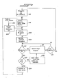
- the microprocessor is caused to enter the program at a predetermined address as shown in Figure 2 at 302.
- the memory is initialized to the "diagnostics off” condition at step 304. All keyers are initialized to the "off” condition (step 306) and the standard generator assignments are made (step 308).
- each generator would be assigned to the seven natural notes in order, as explained in greater detail in our above-mentioned co-pending European patent application. While these generator assignments are subject to change in the course of normal organ operation, the making of initial assignments reduces processing time.
- the program checks to see whether the organ is in the diagnostic mode.
- step 304 Since step 304 has just initialized the organ to the diagnostics off condition, the program will find that the organ is not in the diagnostic mode and will proceed to the normal program shown schematically as step 312.
- the normal organ program 312 continually scans the switch matrix 130 for any change in the status of the switches, as described above. After each scan of the switches in a normal musical performance, the normal organ program will conduct a test 314 to see whether the status of the switches indicates that the diagnostic mode is to be entered. If this test proves negative, the program returns to step 310.
- diagnostics is entered by the operation of a unique combination of switches on the organ.
- test 314 directs the program to step 316 which sets diagnostics "on" and the diagnostic section number to zero.
- Step 318 then initializes the various mode conditions of the organ for diagnostics.
- Steps 306 and 308 are repeated to turn all of the keyers off. and implement the standard generator assignment (since the actual generator assignments may have changed from their initialized condition).
- Step 310 now determines that the organ is in the diagnostic mode and step 320 will indicate that the minor bar switch has not been actuated since the last cycle.
- Step 322 causes the organ to check the switch status.
- step 318 Since the switches were just initialized at step 318, no new switches will be detected and no update will be made. The program will therefore cause the scan routine to continue with step 312. Following each scan of the control switches of the organ, the program will proceed through steps 314, 310, 320, 322 and back to 312. If step 322 detects that one of the keys involved in an active test sequence has been added, it will cause the normal organ program 312 to compute and output the data called for by that test, rather than the actual key played.
- one test required to be performed is to test generator operation for all possible assignment.
- step 318 initializes one of the keyers of each of the generators to be turned on by any key of the upper manual.
- the frequency address of the corresponding generator is decremented by step 322, and the keyer is again turned on.
- one of the keyers of the next generator is assigned to be turned on by any key of the upper manual, and the sequence is repeated.
- step 322 The updating of the test condition is done by step 322. All that is required is that the frequency address code be decremented as described above. When the address reaches zero, it is set back to seven, and the generator number is decremented. The keyer data need not be tested since the same data will output the appropriate keyer when assigned by the normal program to a different generator.
- the generator number is decremented by step 322 with the generators left in their standard frequency assignments.
- the first generator is again accessed, and the octave of the keyer data is decremented.
- the simplest possible program causes the keyers to sequence through a frequency pattern that can be recognized by a musically unskilled technician.
- the diagnostic routine In certain portions of the diagnostic routine, it is necessary to sequence through a large number of gates and keyers. In these stages of diagnostics, if a test sequence key is held down, then the portion of the program which updates the test condition (step 322) will automatically advance the diagnostic routine to each successive test at one second intervals, and will cause the program to compute and output the appropriate test data. During the diagnostic procedure, the normal program also causes the address of the test in progress to be output via lighted push button or digital displays if such features are available on the organ.
- the minor bar can be actuated, and this will be detected by test 320, and step 324 will cause the diagnostic routine to initialize to the next section.
- the minor bar By use of the minor bar to increment from section to section, portions of the diagnostic routine can be bypassed and repeated as desired.
- the organ can be returned to normal operation by turning.the power off and then back on again.
- the normal organ program ordinarily detects switch data which it uses to compute output information for control of the various keyers and generators.
- switch information is intercepted and causes the normal organ program to compute test data instead of more conventional output data.
- the diagnostic program operates through the normal organ program, the diagnostics feature can be implemented using-relatively little (typically 5%) of the program memory.
- the first step in the diagnostic routine is to check the.operation of each of the input switches. To do this, the diagnostic routine will cause all of the indicator.lights to light whenever any key or tab switch is actuated. Simultaneous key and tab actuation will turn all of the indicator lights off.
- each generator is assigned to one key.
- the diagnostic routine will simulate a played key on each manual. This key will sound as each tab is operated in sequence.
- the voice outputs can be monitored,as each tab is operated to confirm proper operation.
- operation of .a rhythm pattern tab automatically starts the rhythm pattern on the down beat, without the need for manual operation of other tabs or keys.
- the indicator lights can also be used to provide feedback in this mode.
- the programmable generators and gates must be tested.
- all of the programmable generators are sequenced through all possible address combinations to the data selectors as described above.
- all of the sustain keyers are sequenced with both sustain and damped envelopes, all of the output switching paths controlled by the tab switches are sequenced, and all of the rhythm output lines are sequenced.
- the diagnostic routine can automatically check each and every path through every component of the organ. Because of the large number of possible combinations, and the complexity of the priorities pursuant to which generators and keyers are assigned in the normal organ mode, it would be extremely difficult to sequence through all possible combinations without the help of the diagnostic system.
- the indicator lights provide a means of communication between the microprocessor and the technician. These indicator lights will ordinarily be caused to indicate the section of the diagnostic routine presently under way. However, when the diagnostic routine is interrupted, these indicator lights can be used to output an address which can enable the service technician to identify in the service manual the location of the fault.
Landscapes
- Physics & Mathematics (AREA)
- Engineering & Computer Science (AREA)
- Acoustics & Sound (AREA)
- Multimedia (AREA)
- Electrophonic Musical Instruments (AREA)
Applications Claiming Priority (2)
| Application Number | Priority Date | Filing Date | Title |
|---|---|---|---|
| US16332080A | 1980-06-26 | 1980-06-26 | |
| US163320 | 1980-06-26 |
Publications (2)
| Publication Number | Publication Date |
|---|---|
| EP0044609A2 true EP0044609A2 (fr) | 1982-01-27 |
| EP0044609A3 EP0044609A3 (fr) | 1984-01-25 |
Family
ID=22589492
Family Applications (1)
| Application Number | Title | Priority Date | Filing Date |
|---|---|---|---|
| EP81302477A Withdrawn EP0044609A3 (fr) | 1980-06-26 | 1981-06-04 | Instrument de musique électronique comprenant un détecteur de faute interne |
Country Status (5)
| Country | Link |
|---|---|
| EP (1) | EP0044609A3 (fr) |
| JP (1) | JPS5729095A (fr) |
| AU (1) | AU7148981A (fr) |
| BR (1) | BR8103971A (fr) |
| CA (1) | CA1165600A (fr) |
Cited By (3)
| Publication number | Priority date | Publication date | Assignee | Title |
|---|---|---|---|---|
| EP0847005A3 (fr) * | 1996-12-06 | 2001-07-18 | King Jim Co., Ltd. | Processeur d'informations de caractères |
| EP1624444A1 (fr) * | 2004-08-06 | 2006-02-08 | Yamaha Corporation | Instrument de musique capable de diagnostiquer des composants mécaniques et électroniques, et dispositif de diagnose utilisé à ce but. |
| DE102005013138A1 (de) * | 2005-03-22 | 2006-09-28 | Zf Friedrichshafen Ag | Verfahren und Vorrichtung zum Überwachen der Funktion von mehreren nacheinander angesteuerten Funktionskomponenten |
Families Citing this family (3)
| Publication number | Priority date | Publication date | Assignee | Title |
|---|---|---|---|---|
| JPS6083450A (ja) * | 1983-10-14 | 1985-05-11 | Fujitsu General Ltd | 動態デ−タ収集方法 |
| JPH01136436A (ja) * | 1987-11-24 | 1989-05-29 | Mitsubishi Electric Corp | 空車呼出方式 |
| JP2830709B2 (ja) * | 1993-09-08 | 1998-12-02 | ヤマハ株式会社 | 電子楽器 |
Family Cites Families (1)
| Publication number | Priority date | Publication date | Assignee | Title |
|---|---|---|---|---|
| US4070565A (en) * | 1976-08-18 | 1978-01-24 | Zehntel, Inc. | Programmable tester method and apparatus |
-
1981
- 1981-04-01 CA CA000374407A patent/CA1165600A/fr not_active Expired
- 1981-05-29 JP JP8241281A patent/JPS5729095A/ja active Pending
- 1981-06-04 EP EP81302477A patent/EP0044609A3/fr not_active Withdrawn
- 1981-06-10 AU AU71489/81A patent/AU7148981A/en not_active Abandoned
- 1981-06-24 BR BR8103971A patent/BR8103971A/pt unknown
Cited By (4)
| Publication number | Priority date | Publication date | Assignee | Title |
|---|---|---|---|---|
| EP0847005A3 (fr) * | 1996-12-06 | 2001-07-18 | King Jim Co., Ltd. | Processeur d'informations de caractères |
| EP1624444A1 (fr) * | 2004-08-06 | 2006-02-08 | Yamaha Corporation | Instrument de musique capable de diagnostiquer des composants mécaniques et électroniques, et dispositif de diagnose utilisé à ce but. |
| US7094961B2 (en) | 2004-08-06 | 2006-08-22 | Yamaha Corporation | Musical instrument capable of diagnosing electronic and mechanical components and diagnostic system used therein |
| DE102005013138A1 (de) * | 2005-03-22 | 2006-09-28 | Zf Friedrichshafen Ag | Verfahren und Vorrichtung zum Überwachen der Funktion von mehreren nacheinander angesteuerten Funktionskomponenten |
Also Published As
| Publication number | Publication date |
|---|---|
| JPS5729095A (en) | 1982-02-16 |
| EP0044609A3 (fr) | 1984-01-25 |
| BR8103971A (pt) | 1982-03-09 |
| CA1165600A (fr) | 1984-04-17 |
| AU7148981A (en) | 1982-01-07 |
Similar Documents
| Publication | Publication Date | Title |
|---|---|---|
| US4059039A (en) | Electrical musical instrument with chord generation | |
| US3567838A (en) | Musical instrument rhythm system having provision for introducing automatically selected chord components | |
| US4344345A (en) | Automatic rhythm accompaniment system | |
| US4499807A (en) | Key data entry system for an electronic musical instrument | |
| US5393927A (en) | Automatic accompaniment apparatus with indexed pattern searching | |
| US4624170A (en) | Electronic musical instrument with automatic accompaniment function | |
| GB1564914A (en) | Automatically playing a tonal accompaniment in an electronic musical instrument | |
| US3918341A (en) | Automatic chord and rhythm system for electronic organ | |
| US4058043A (en) | Programmable rhythm apparatus | |
| US4300430A (en) | Chord recognition system for an electronic musical instrument | |
| EP0044609A2 (fr) | Instrument de musique électronique comprenant un détecteur de faute interne | |
| JPH0222396B2 (fr) | ||
| US4387618A (en) | Harmony generator for electronic organ | |
| US4616547A (en) | Improviser circuit and technique for electronic musical instrument | |
| US4887503A (en) | Automatic accompaniment apparatus for electronic musical instrument | |
| US4481853A (en) | Electronic keyboard musical instrument capable of inputting rhythmic patterns | |
| US5523521A (en) | Electronic musical instrument including at least two tone-generation assigners | |
| US4543869A (en) | Electronic musical instrument producing chord tones utilizing channel assignment | |
| US5074183A (en) | Musical-tone-signal-generating apparatus having mixed tone color designation states | |
| US4248118A (en) | Harmony recognition technique application | |
| US3921491A (en) | Bass system for automatic root fifth and pedal sustain | |
| US4646610A (en) | Electronic musical instrument with automatic ending accompaniment function | |
| US4100831A (en) | Automatic digital circuit for generating chords in a digital organ | |
| JP2689812B2 (ja) | 自動演奏装置 | |
| JPS62159189A (ja) | 自動リズム演秦装置 |
Legal Events
| Date | Code | Title | Description |
|---|---|---|---|
| PUAI | Public reference made under article 153(3) epc to a published international application that has entered the european phase |
Free format text: ORIGINAL CODE: 0009012 |
|
| AK | Designated contracting states |
Designated state(s): DE GB IT NL |
|
| RBV | Designated contracting states (corrected) |
Designated state(s): DE GB IT NL |
|
| 17P | Request for examination filed |
Effective date: 19820716 |
|
| PUAL | Search report despatched |
Free format text: ORIGINAL CODE: 0009013 |
|
| AK | Designated contracting states |
Designated state(s): DE GB IT NL |
|
| STAA | Information on the status of an ep patent application or granted ep patent |
Free format text: STATUS: THE APPLICATION IS DEEMED TO BE WITHDRAWN |
|
| 18D | Application deemed to be withdrawn |
Effective date: 19840726 |
|
| RIN1 | Information on inventor provided before grant (corrected) |
Inventor name: UETRECHT, DALE MARSHALL |