EP0044773A1 - Landfahrzeug mit elektronischer Regelung - Google Patents
Landfahrzeug mit elektronischer Regelung Download PDFInfo
- Publication number
- EP0044773A1 EP0044773A1 EP81401119A EP81401119A EP0044773A1 EP 0044773 A1 EP0044773 A1 EP 0044773A1 EP 81401119 A EP81401119 A EP 81401119A EP 81401119 A EP81401119 A EP 81401119A EP 0044773 A1 EP0044773 A1 EP 0044773A1
- Authority
- EP
- European Patent Office
- Prior art keywords
- wheels
- vehicle
- vehicle according
- pair
- wheel
- Prior art date
- Legal status (The legal status is an assumption and is not a legal conclusion. Google has not performed a legal analysis and makes no representation as to the accuracy of the status listed.)
- Granted
Links
- 230000001133 acceleration Effects 0.000 claims abstract description 15
- 238000000034 method Methods 0.000 claims abstract description 5
- 230000009471 action Effects 0.000 claims description 9
- 238000004804 winding Methods 0.000 claims description 8
- 230000004048 modification Effects 0.000 claims description 4
- 238000012986 modification Methods 0.000 claims description 4
- 210000000056 organ Anatomy 0.000 claims 1
- 238000001514 detection method Methods 0.000 description 4
- 238000010586 diagram Methods 0.000 description 3
- 230000000694 effects Effects 0.000 description 3
- 230000008859 change Effects 0.000 description 2
- 230000006870 function Effects 0.000 description 2
- 230000007935 neutral effect Effects 0.000 description 2
- 230000000630 rising effect Effects 0.000 description 2
- 238000005286 illumination Methods 0.000 description 1
- 230000000977 initiatory effect Effects 0.000 description 1
- 230000008447 perception Effects 0.000 description 1
- 230000000717 retained effect Effects 0.000 description 1
- 230000001360 synchronised effect Effects 0.000 description 1
Images


Classifications
-
- B—PERFORMING OPERATIONS; TRANSPORTING
- B62—LAND VEHICLES FOR TRAVELLING OTHERWISE THAN ON RAILS
- B62D—MOTOR VEHICLES; TRAILERS
- B62D11/00—Steering non-deflectable wheels; Steering endless tracks or the like
- B62D11/02—Steering non-deflectable wheels; Steering endless tracks or the like by differentially driving ground-engaging elements on opposite vehicle sides
- B62D11/04—Steering non-deflectable wheels; Steering endless tracks or the like by differentially driving ground-engaging elements on opposite vehicle sides by means of separate power sources
-
- B—PERFORMING OPERATIONS; TRANSPORTING
- B60—VEHICLES IN GENERAL
- B60L—PROPULSION OF ELECTRICALLY-PROPELLED VEHICLES; SUPPLYING ELECTRIC POWER FOR AUXILIARY EQUIPMENT OF ELECTRICALLY-PROPELLED VEHICLES; ELECTRODYNAMIC BRAKE SYSTEMS FOR VEHICLES IN GENERAL; MAGNETIC SUSPENSION OR LEVITATION FOR VEHICLES; MONITORING OPERATING VARIABLES OF ELECTRICALLY-PROPELLED VEHICLES; ELECTRIC SAFETY DEVICES FOR ELECTRICALLY-PROPELLED VEHICLES
- B60L15/00—Methods, circuits, or devices for controlling the traction-motor speed of electrically-propelled vehicles
- B60L15/20—Methods, circuits, or devices for controlling the traction-motor speed of electrically-propelled vehicles for control of the vehicle or its driving motor to achieve a desired performance, e.g. speed, torque, programmed variation of speed
- B60L15/2036—Electric differentials, e.g. for supporting steering vehicles
-
- B—PERFORMING OPERATIONS; TRANSPORTING
- B60—VEHICLES IN GENERAL
- B60L—PROPULSION OF ELECTRICALLY-PROPELLED VEHICLES; SUPPLYING ELECTRIC POWER FOR AUXILIARY EQUIPMENT OF ELECTRICALLY-PROPELLED VEHICLES; ELECTRODYNAMIC BRAKE SYSTEMS FOR VEHICLES IN GENERAL; MAGNETIC SUSPENSION OR LEVITATION FOR VEHICLES; MONITORING OPERATING VARIABLES OF ELECTRICALLY-PROPELLED VEHICLES; ELECTRIC SAFETY DEVICES FOR ELECTRICALLY-PROPELLED VEHICLES
- B60L50/00—Electric propulsion with power supplied within the vehicle
- B60L50/50—Electric propulsion with power supplied within the vehicle using propulsion power supplied by batteries or fuel cells
- B60L50/60—Electric propulsion with power supplied within the vehicle using propulsion power supplied by batteries or fuel cells using power supplied by batteries
-
- Y—GENERAL TAGGING OF NEW TECHNOLOGICAL DEVELOPMENTS; GENERAL TAGGING OF CROSS-SECTIONAL TECHNOLOGIES SPANNING OVER SEVERAL SECTIONS OF THE IPC; TECHNICAL SUBJECTS COVERED BY FORMER USPC CROSS-REFERENCE ART COLLECTIONS [XRACs] AND DIGESTS
- Y02—TECHNOLOGIES OR APPLICATIONS FOR MITIGATION OR ADAPTATION AGAINST CLIMATE CHANGE
- Y02T—CLIMATE CHANGE MITIGATION TECHNOLOGIES RELATED TO TRANSPORTATION
- Y02T10/00—Road transport of goods or passengers
- Y02T10/60—Other road transportation technologies with climate change mitigation effect
- Y02T10/64—Electric machine technologies in electromobility
-
- Y—GENERAL TAGGING OF NEW TECHNOLOGICAL DEVELOPMENTS; GENERAL TAGGING OF CROSS-SECTIONAL TECHNOLOGIES SPANNING OVER SEVERAL SECTIONS OF THE IPC; TECHNICAL SUBJECTS COVERED BY FORMER USPC CROSS-REFERENCE ART COLLECTIONS [XRACs] AND DIGESTS
- Y02—TECHNOLOGIES OR APPLICATIONS FOR MITIGATION OR ADAPTATION AGAINST CLIMATE CHANGE
- Y02T—CLIMATE CHANGE MITIGATION TECHNOLOGIES RELATED TO TRANSPORTATION
- Y02T10/00—Road transport of goods or passengers
- Y02T10/60—Other road transportation technologies with climate change mitigation effect
- Y02T10/70—Energy storage systems for electromobility, e.g. batteries
-
- Y—GENERAL TAGGING OF NEW TECHNOLOGICAL DEVELOPMENTS; GENERAL TAGGING OF CROSS-SECTIONAL TECHNOLOGIES SPANNING OVER SEVERAL SECTIONS OF THE IPC; TECHNICAL SUBJECTS COVERED BY FORMER USPC CROSS-REFERENCE ART COLLECTIONS [XRACs] AND DIGESTS
- Y02—TECHNOLOGIES OR APPLICATIONS FOR MITIGATION OR ADAPTATION AGAINST CLIMATE CHANGE
- Y02T—CLIMATE CHANGE MITIGATION TECHNOLOGIES RELATED TO TRANSPORTATION
- Y02T10/00—Road transport of goods or passengers
- Y02T10/60—Other road transportation technologies with climate change mitigation effect
- Y02T10/72—Electric energy management in electromobility
Definitions
- the present invention relates to an electronically controlled land vehicle.
- the invention also relates to a piloting method applicable to such a vehicle.
- each drive wheel is made integral with a variable speed electric motor whose torque is adjusted by a suitable action of the driver on a guide member such as lever or lever.
- the driver chooses at any time the torque applied to each wheel, in order to obtain the changes in trajectory and speed that he wishes to impose on his vehicle, or in order to maintain it on a given trajectory, straight or curvilinear.
- the vehicle has one or two freely steerable wheels (for example, a non-guided front wheel in the case of a vehicle of the tricycle type) the position of this or these wheels, not known to the driver, may disturb the trajectory, and the correction that the driver must make can only intervene after the discovery of the unexpected deviation of his vehicle; this is particularly sensitive during maneuvers requiring successive changes of direction of market.
- the driver's intervention, through perception, reflection and action introduces a delay prejudicial to safe and precise driving.
- the present invention aims to produce a vehicle which is insensitive to disturbances such as those mentioned above, as well as a control method applicable to such a vehicle.
- the electronically controlled land vehicle comprises at least one pair of side wheels driven by respective electric motors, means for communicating to each of the wheels of this pair its own driving action, and a source of 'electric energy. It is characterized in that it comprises a computer associated with a reference clock, connected on the one hand to a control member to receive instructions for modification of trajectory and speed, and on the other hand to position detectors relative to the fixed and mobile parts of the respective driving wheels, and finally to the control members of the respective motors of the wheels for transmitting to these members orders determining the exchange of energy with the respective wheels with a view to giving them their own differential acceleration to enforce the instructions for changes to the trajectory and speed.
- the computer actuates the wheels symmetrically or differentially to ensure compliance with a trajectory and a speed corresponding to a previously given setpoint. This action has the effect of alleviating fortuitous deviations caused by various incidents, without the pilot even having to note these deviations.
- the computer comprises as many programming blocks as there are drive wheels, and these blocks are interconnected by links allowing them to exchange their information.
- the wheel motors are variable reluctance motors each comprising a toothed rotor cooperating with a toothed stator provided with windings connected to a source of electrical energy by means of switching members connected to the programming block to send pulses of predetermined intensity and duration to the windings.
- the vehicle comprises a scanner of the intensity of each pulse delivered to the engine, and this scanner is connected to a comparison stage with a reference value of the intensity produced by the calculation stage.
- the intensity setpoint is produced by the computer as a function of the actual measured speed and the desired speed.
- the computer according to the comparison of the intensities, modulates the chopping of the pulses to make the actual intensity equal to the set intensity.
- the vehicle also advantageously comprises a relative position detector of the fixed and mobile parts of each wheel, and this stage is connected to the programming block which determines the phase difference between a reference position of the motor and the start of the electrical pulse in the windings.
- the computer adjusts this phase difference to define slow or fast walking, or braking adapted to slow or fast speed.
- the vehicle piloting method in particular for ensuring the registration in a given curve of a vehicle comprising at least one pair of independent driving side wheels, and means for communicating to each of the wheels of this pair a clean driving action, is characterized in that, to cause the vehicle to turn, a predetermined difference in acceleration is ensured between the wheels of the same pair, the greatest acceleration being communicated to the wheel located outside the curve. This difference is maintained until the radius of curvature of the trajectory of the vehicle corresponds to that of the circular part of the curve to be described, after which the accelerations communicated to the wheels are kept equal, until causes an increase in the radius of curvature corresponding to the exit from the turn.
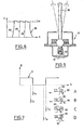
- a vehicle is carried by a pair of driving wheels 1 and a steerable tricycle wheel 2.
- the wheels 1 are driving and each comprise a serrated rotor 3 cooperating with a stator 4 secured to the vehicle (FIG. 2) and provided with windings to constitute a synchronous motor with variable reluctance.
- the number of stator switches per wheel revolution is relatively high, from a few tens to several hundred.
- the stator windings 4 are connected to a battery 5 by means of a switch 6 which, in the example described, is constituted by thyristors controlled from a programming block 7 associated with a clock 8 by l line 9.
- the wheels 1 are also provided with detection members constituted by a number of photoelectric cells 11 fixed to the stator and cooperating with teeth 12 formed on the rotor (FIGS. 2 and 3), to detect the relative positions of the stator and rotor.
- a fitness stage 13 (FIG. 4)
- a detection stage 14 which measures the duration between the pulses emitted by the cells and which also detects the direction of rotation of the wheel 1, thanks to the fact that the number of cells is greater than one.
- This duration and direction information is transmitted to block 7 in digital form respectively by lines 15 and 16.
- a control member 17 ( Figures 1 and 5) comprises a lever 18 tiltable in all directions, and the end of which carries a lamp 19 arranged to illuminate a group 21 of photoelectric cells. It is understood that, according to the direction of the inclination given to the lever 18 (front, rear, left, right), and according to the inclination angle, the differential illumination of the cells will be modified, and that the resulting signal will define at both a direction of travel and an acceleration, the vehicle direction signal corresponding to different acceleration instructions sent respectively to block 7 and to a similar block (not shown) connected to the other wheel according to a diagram similar to that of FIG. 4. A link 22 between these two blocks allows them to exchange their information, their assembly constituting a computer.
- Direction information reaches block 7 via a detection stage 23, while the acceleration information passes through an analog-digital converter 24.
- block 7 develops an electrical intensity setpoint value of the pulses supplied to the stator and applies this value to a comparison stage 25 which compares it to the actual intensity measured by a scanner 26.
- a link 27 makes it possible to communicate the information relating to the result of this comparison to block 7.
- block 7 modifies, by lines 9, the operating mode of the thyristors. It is in fact understood that the average intensity Im (FIG. 6) during a pulse 28 depends on the instant of the ignitions 29 of the thyristors during this pulse.
- the information relating to the instants of ignition of the thyristors are communicated to the detection stage 14 by a link 31, which allows the stage 14 to determine the phase difference between the start of a pulse 28 and the instant when the wheel passes through a reference position, this instant being defined by one of the photocells 11.
- the square wave signal D emitted by the cell is such that its rising edge occurs when a tooth 32 of the rotor passes exactly in front of a tooth 33 of the stator (FIG. 7-C).
- phase difference information thus produced is transmitted to block 7 by a link 34.
- block 7 modifies the phase difference in order to respect this instruction.
- the pulse is sent at time t i , when tooth 32 of the rotor enters the area of attraction of the stator (position A).
- position B At high speed, we give a certain advance to ignition (position B) by switching on at time t 2-
- Block 7 also includes a memory 34 with modifiable content in which are stored a certain number of permanent instructions, in particular safety instructions, such as speed limits, or a radius of curvature path limit as a function of speed.
- safety instructions such as speed limits, or a radius of curvature path limit as a function of speed.
- the pilot gives a speed and trajectory modification instruction by means of the control member 17, then he returns this member to the neutral position. From this moment, the block 7 and that relating to the other wheel will make these instructions respect despite the vagaries of the journey without intervention of the pilot.
- the computer will modify the power transmitted to the wheels as soon as it notices a tendency to a variation in speed. The same goes for the trajectory. If the setpoint corresponds to a straight line, any initiation of deviation caused for example by an unevenness of the ground will result in an unequal speed of the wheels 1. This difference in speed noted by the computer will cause a differential acceleration of the wheels which will tend to restore instantly the straight path.
- the role of the pilot is limited only to modifying the set values when he wishes.
- control member 17 can be constituted by a stationary handle sensitive to the pressure exerted, by means of strain gauges.
Landscapes
- Engineering & Computer Science (AREA)
- Transportation (AREA)
- Mechanical Engineering (AREA)
- Power Engineering (AREA)
- Chemical & Material Sciences (AREA)
- Combustion & Propulsion (AREA)
- Life Sciences & Earth Sciences (AREA)
- Sustainable Development (AREA)
- Sustainable Energy (AREA)
- Electric Propulsion And Braking For Vehicles (AREA)
Applications Claiming Priority (2)
| Application Number | Priority Date | Filing Date | Title |
|---|---|---|---|
| FR8015870 | 1980-07-18 | ||
| FR8015870A FR2486881A1 (fr) | 1980-07-18 | 1980-07-18 | Vehicule terrestre a commande electronique et procede de pilotage s'y rapportant |
Publications (2)
| Publication Number | Publication Date |
|---|---|
| EP0044773A1 true EP0044773A1 (de) | 1982-01-27 |
| EP0044773B1 EP0044773B1 (de) | 1985-11-13 |
Family
ID=9244270
Family Applications (1)
| Application Number | Title | Priority Date | Filing Date |
|---|---|---|---|
| EP81401119A Expired EP0044773B1 (de) | 1980-07-18 | 1981-07-10 | Landfahrzeug mit elektronischer Regelung |
Country Status (5)
| Country | Link |
|---|---|
| US (1) | US4541051A (de) |
| EP (1) | EP0044773B1 (de) |
| JP (1) | JPS5785505A (de) |
| DE (1) | DE3172897D1 (de) |
| FR (1) | FR2486881A1 (de) |
Cited By (16)
| Publication number | Priority date | Publication date | Assignee | Title |
|---|---|---|---|---|
| WO1984002683A1 (en) * | 1983-01-05 | 1984-07-19 | Towmotor Corp | Motor speed control apparatus |
| WO1984002684A1 (en) * | 1983-01-05 | 1984-07-19 | Towmotor Corp | Dual-motor control apparatus |
| FR2549433A1 (fr) * | 1983-07-20 | 1985-01-25 | Jarret Jean Marie | Vehicule guide par le couple individuel applique a ses roues motrices, et procede pour faire virer un tel vehicule |
| FR2557987A1 (fr) * | 1984-01-11 | 1985-07-12 | Jeulin | Dispositif de correction des ecarts de deplacement des roues d'un mobile programme |
| US4548584A (en) * | 1983-05-10 | 1985-10-22 | Economatics (Education) Limited | Computer controlled mobile device |
| US4555651A (en) * | 1983-01-05 | 1985-11-26 | Towmotor Corporation | Motor speed control apparatus |
| FR2599869A1 (fr) * | 1986-06-09 | 1987-12-11 | Linde Ag | Installation de commande pour vehicule a direction par difference de vitesse |
| GB2166308B (en) * | 1984-10-19 | 1989-05-24 | Kollmorgen Tech Corp | Servomotor control systems |
| EP0232072A3 (de) * | 1986-01-25 | 1989-05-31 | Yale Materials Handling Limited | Fahrzeugsteuervorrichtungen |
| EP0493848A3 (en) * | 1990-12-31 | 1993-03-31 | General Motors Corporation | Electric motor drive and power processing apparatus |
| WO1993008063A1 (de) * | 1991-10-16 | 1993-04-29 | Mannesmann Aktiengesellschaft | Lenkungsunterstützung bei einem nicht-spurgebundenen fahrzeug |
| WO1994026551A3 (en) * | 1993-05-15 | 1995-01-19 | Newton Roy Gingerich | Electric powered small tractor |
| EP0850822A1 (de) * | 1996-12-27 | 1998-07-01 | EXPRESSO DEUTSCHLAND TRANSPORTGERÄTE GmbH | Behindertengerechter selbstfahrender Magazinwagen |
| NL1014182C2 (nl) * | 2000-01-26 | 2001-07-27 | Special Products For Industry | Wiel voorzien van aandrijfmiddelen. |
| EP2769617A1 (de) | 2013-02-20 | 2014-08-27 | Trioliet Holding B.V. | Unbemannter Futterwagen |
| US9233603B2 (en) | 2000-01-26 | 2016-01-12 | E-Traction Europe B.V. | Wheel provided with driving means |
Families Citing this family (27)
| Publication number | Priority date | Publication date | Assignee | Title |
|---|---|---|---|---|
| IL84382A (en) * | 1987-11-05 | 1995-12-08 | Carcom Computerized Vehicle Lt | Computerized electrical vehicle |
| ES2027099A6 (es) * | 1990-03-21 | 1992-05-16 | Univ De Oviedo Representada Po | Diferencial electronico autoblocante para vehiculos de traccion electrica. |
| FR2681449B1 (fr) * | 1991-09-12 | 1993-12-10 | Giat Industries | Procede et dispositif de commande du virage d'un vehicule chenille ou a roues non directrices. |
| US5323866A (en) * | 1993-03-01 | 1994-06-28 | Hydro-Quebec | Power steering system |
| DE9311075U1 (de) * | 1993-07-24 | 1994-11-24 | Strothmann, Rolf, Dr., 66123 Saarbrücken | Elektrischer Antrieb eines von Hand gezogenen oder geschobenen, fahrbaren Gegenstands |
| US5402344A (en) * | 1993-08-23 | 1995-03-28 | Martin Marietta Energy Systems, Inc. | Method for controlling a vehicle with two or more independently steered wheels |
| US5445234A (en) * | 1994-02-16 | 1995-08-29 | General Motors Corporation | Dual drive transmission |
| GB2316922B (en) * | 1996-09-04 | 2000-10-25 | Carver Plc | Apparatus for moving vehicles such as trailers and trolleys |
| US5931881A (en) * | 1996-12-11 | 1999-08-03 | Caterpillar Paving Products Inc. | Steering curve calibration method and apparatus for a rubber tired paver |
| USD415214S (en) * | 1998-01-28 | 1999-10-12 | Mattel, Inc. | Children's ride-on vehicle |
| US6095268A (en) * | 1998-01-28 | 2000-08-01 | Mattel, Inc. | Children's ride-on vehicle with independently driven and reversible wheels |
| USD418546S (en) * | 1998-01-28 | 2000-01-04 | Mattel, Inc. | Children's ride-on vehicle |
| USD414221S (en) | 1998-01-28 | 1999-09-21 | Mattel, Inc. | Children's ride-on vehicle |
| US6092468A (en) * | 1998-03-23 | 2000-07-25 | Daimlerchrysler Ag | Torque controlled mechanism for moving and steering a transit vehicle |
| JP4178955B2 (ja) * | 2001-04-20 | 2008-11-12 | セイコーエプソン株式会社 | 駆動制御 |
| US7116065B2 (en) | 2003-10-28 | 2006-10-03 | Honda Motor Co., Ltd. | Electric vehicle |
| TWM270937U (en) * | 2004-10-26 | 2005-07-21 | Yung-Cheng Chen | Diversion differential controlling structure for scooter |
| EP1693232A1 (de) * | 2005-02-22 | 2006-08-23 | Heuliez | Geländegängiges Amphibienfahrzeug |
| JP5540894B2 (ja) * | 2010-05-31 | 2014-07-02 | 日産自動車株式会社 | 車両の制振制御装置 |
| GB2514106A (en) * | 2013-05-13 | 2014-11-19 | Stewart Golf Ltd | Wheel assembly for a golf trolley |
| CA2983986C (en) | 2017-10-26 | 2019-01-15 | Rovibec Inc. | Autonomous vehicle for pushing feed, methods and systems thereof |
| US12030402B2 (en) | 2020-11-09 | 2024-07-09 | Zimeno Inc. | Battery swap system |
| US11407298B1 (en) | 2021-11-15 | 2022-08-09 | Amos Power, Inc. | Removable battery unit for an electric vehicle |
| US11364959B1 (en) | 2021-12-27 | 2022-06-21 | Amos Power, Inc. | Modular robotic vehicle |
| USD1014573S1 (en) | 2022-04-01 | 2024-02-13 | Amos Power, Inc. | Removable track unit for a robotic vehicle |
| USD1014569S1 (en) | 2022-04-01 | 2024-02-13 | Amos Power, Inc. | Robotic vehicle |
| US11547035B1 (en) | 2022-05-24 | 2023-01-10 | Amos Power, Inc. | Lift assist for an electrically driven hitch on an robotic vehicle |
Citations (5)
| Publication number | Priority date | Publication date | Assignee | Title |
|---|---|---|---|---|
| GB1209245A (en) * | 1967-03-22 | 1970-10-21 | Jean Jarret | A directional and propulsive control device for an electrical vehicle |
| FR2084268A5 (de) * | 1970-03-06 | 1971-12-17 | Siemens Ag | |
| US3970160A (en) * | 1973-11-06 | 1976-07-20 | William Nowick | Control means for electrically powered transportation means |
| FR2325533A1 (fr) * | 1975-09-23 | 1977-04-22 | Eaton Gmbh | Ensemble de propulsion electrique pour vehicules en particulier pour chariots elevateurs |
| US4196785A (en) * | 1977-02-16 | 1980-04-08 | Downing James H Jr | All-electric A.C. tractor |
Family Cites Families (6)
| Publication number | Priority date | Publication date | Assignee | Title |
|---|---|---|---|---|
| GB1200895A (en) * | 1966-11-14 | 1970-08-05 | Sevcon Eng Ltd | Improvements in electrically operated drive systems |
| GB1240979A (en) * | 1970-03-26 | 1971-07-28 | Ford Motor Co | Reluctance motor power circuit |
| US3688169A (en) * | 1971-02-18 | 1972-08-29 | Nippon Yusoki Co Ltd | Brushless motor control apparatus for an electric vehicle |
| US3848166A (en) * | 1973-01-22 | 1974-11-12 | Parker L | Silicon controlled rectifier type inverter for electric motors |
| US4110668A (en) * | 1977-01-24 | 1978-08-29 | Sevcon Limited | Thyristor pulse controller for plural loads |
| US4158196A (en) * | 1977-04-11 | 1979-06-12 | Crawford George E Jr | Man-machine interface system |
-
1980
- 1980-07-18 FR FR8015870A patent/FR2486881A1/fr active Granted
-
1981
- 1981-07-10 DE DE8181401119T patent/DE3172897D1/de not_active Expired
- 1981-07-10 EP EP81401119A patent/EP0044773B1/de not_active Expired
- 1981-07-17 JP JP56110992A patent/JPS5785505A/ja active Pending
-
1984
- 1984-04-05 US US06/596,579 patent/US4541051A/en not_active Expired - Lifetime
Patent Citations (5)
| Publication number | Priority date | Publication date | Assignee | Title |
|---|---|---|---|---|
| GB1209245A (en) * | 1967-03-22 | 1970-10-21 | Jean Jarret | A directional and propulsive control device for an electrical vehicle |
| FR2084268A5 (de) * | 1970-03-06 | 1971-12-17 | Siemens Ag | |
| US3970160A (en) * | 1973-11-06 | 1976-07-20 | William Nowick | Control means for electrically powered transportation means |
| FR2325533A1 (fr) * | 1975-09-23 | 1977-04-22 | Eaton Gmbh | Ensemble de propulsion electrique pour vehicules en particulier pour chariots elevateurs |
| US4196785A (en) * | 1977-02-16 | 1980-04-08 | Downing James H Jr | All-electric A.C. tractor |
Cited By (25)
| Publication number | Priority date | Publication date | Assignee | Title |
|---|---|---|---|---|
| WO1984002684A1 (en) * | 1983-01-05 | 1984-07-19 | Towmotor Corp | Dual-motor control apparatus |
| US4471273A (en) * | 1983-01-05 | 1984-09-11 | Towmotor Corporation | Dual-motor control apparatus |
| US4555651A (en) * | 1983-01-05 | 1985-11-26 | Towmotor Corporation | Motor speed control apparatus |
| WO1984002683A1 (en) * | 1983-01-05 | 1984-07-19 | Towmotor Corp | Motor speed control apparatus |
| US4548584A (en) * | 1983-05-10 | 1985-10-22 | Economatics (Education) Limited | Computer controlled mobile device |
| FR2549433A1 (fr) * | 1983-07-20 | 1985-01-25 | Jarret Jean Marie | Vehicule guide par le couple individuel applique a ses roues motrices, et procede pour faire virer un tel vehicule |
| DE3426525A1 (de) * | 1983-07-20 | 1985-01-31 | Jacques Les Mureaux Jarret | Bodenfahrzeug und verfahren zu seiner lenkung |
| US4579181A (en) * | 1983-07-20 | 1986-04-01 | Jarret Jean M B | Vehicle guided by the individual torque applied to its driving wheels and a method for turning said vehicle |
| FR2557987A1 (fr) * | 1984-01-11 | 1985-07-12 | Jeulin | Dispositif de correction des ecarts de deplacement des roues d'un mobile programme |
| EP0152313A1 (de) * | 1984-01-11 | 1985-08-21 | JEULIN, Société dite: | Schaltung zur Korrektur der Abweichung der Räder eines programmierten mobilen Gerätes |
| GB2166308B (en) * | 1984-10-19 | 1989-05-24 | Kollmorgen Tech Corp | Servomotor control systems |
| EP0232072A3 (de) * | 1986-01-25 | 1989-05-31 | Yale Materials Handling Limited | Fahrzeugsteuervorrichtungen |
| FR2599869A1 (fr) * | 1986-06-09 | 1987-12-11 | Linde Ag | Installation de commande pour vehicule a direction par difference de vitesse |
| EP0493848A3 (en) * | 1990-12-31 | 1993-03-31 | General Motors Corporation | Electric motor drive and power processing apparatus |
| US5469928A (en) * | 1991-10-06 | 1995-11-28 | Mannesmann Aktiengesellschaft | Assisted steering system for non-trackbound vehicle |
| WO1993008063A1 (de) * | 1991-10-16 | 1993-04-29 | Mannesmann Aktiengesellschaft | Lenkungsunterstützung bei einem nicht-spurgebundenen fahrzeug |
| WO1994026551A3 (en) * | 1993-05-15 | 1995-01-19 | Newton Roy Gingerich | Electric powered small tractor |
| US5743347A (en) * | 1993-05-15 | 1998-04-28 | Gingerich; Newton Roy | Electric powered small tractor |
| EP0850822A1 (de) * | 1996-12-27 | 1998-07-01 | EXPRESSO DEUTSCHLAND TRANSPORTGERÄTE GmbH | Behindertengerechter selbstfahrender Magazinwagen |
| NL1014182C2 (nl) * | 2000-01-26 | 2001-07-27 | Special Products For Industry | Wiel voorzien van aandrijfmiddelen. |
| WO2001054939A3 (en) * | 2000-01-26 | 2002-02-14 | Special Products For Industry | Wheel provided with driving means |
| CZ299074B6 (cs) * | 2000-01-26 | 2008-04-16 | Special Products For Industry V. O. F. | Kolo vybavené hnacími prostredky, sestava kol, vozidlo a zpusob koordinace otácek kol na vozidle |
| JP2012066822A (ja) * | 2000-01-26 | 2012-04-05 | Special Products For Industry Vof | 車輪ストラット |
| US9233603B2 (en) | 2000-01-26 | 2016-01-12 | E-Traction Europe B.V. | Wheel provided with driving means |
| EP2769617A1 (de) | 2013-02-20 | 2014-08-27 | Trioliet Holding B.V. | Unbemannter Futterwagen |
Also Published As
| Publication number | Publication date |
|---|---|
| JPS5785505A (en) | 1982-05-28 |
| FR2486881B1 (de) | 1983-08-05 |
| EP0044773B1 (de) | 1985-11-13 |
| DE3172897D1 (en) | 1985-12-19 |
| US4541051A (en) | 1985-09-10 |
| FR2486881A1 (fr) | 1982-01-22 |
Similar Documents
| Publication | Publication Date | Title |
|---|---|---|
| EP0044773A1 (de) | Landfahrzeug mit elektronischer Regelung | |
| FR2495088A1 (fr) | Systeme de direction pour vehicules a quatre roues directrices comportant une commande des roues arriere en fonction du mouvement du vehicule | |
| EP3027496B1 (de) | Vorrichtung und verfahren zur regelung der hilfsleistung eines fahrrads mit elektrischem hilfsantrieb | |
| EP0798205B1 (de) | Verfahren zum Betrieb eines muskelkraft-betriebenen Fahrzeuges und Fahrzeug | |
| FR2660258A1 (fr) | Vehicule electrique a vitesse reglable en toute securite. | |
| EP0626287A1 (de) | Fahrzeug versehen mit einem elektrischen und mechanischem Bremssystem | |
| FR2701443A1 (fr) | Dispositif de commande, notamment direction pour véhicules automobiles. | |
| FR2768375A1 (fr) | Dispositif de stabilisation de marche destine a etre installe sur un vehicule | |
| FR2866301A1 (fr) | Systeme de direction assistee electrique pour un vehicule | |
| FR2819473A1 (fr) | Dispositif de commande d'une direction assistee electrique | |
| FR2550871A1 (fr) | Dipositif destine a exploiter le couple maximal de l'unite d'entrainement des systemes d'entrainement de vehicules ou de convoyeurs | |
| FR2787757A1 (fr) | Systeme de direction pour vehicules automobiles | |
| FR2768376A1 (fr) | Dispositif d'accouplement entre les roues gauche et droite d'un vehicule | |
| EP1316490B1 (de) | Elektrische Lenkung für Fahrzeuge | |
| FR2809369A1 (fr) | Dispositif de direction pour vehicule automobile | |
| JP2023054237A (ja) | 人力駆動車用制御装置 | |
| FR2949421A1 (fr) | Dispositif de controle de trajectoire pour vehicule etroit a motorisation electrique et inclinaison asservie | |
| FR2832682A1 (fr) | Dispositif de commande pour direction electrique active | |
| JP3105570B2 (ja) | 電動モータ付き人力駆動装置 | |
| FR2549433A1 (fr) | Vehicule guide par le couple individuel applique a ses roues motrices, et procede pour faire virer un tel vehicule | |
| FR2994936A1 (fr) | Procede de regulation de l'assistance electrique d'un velo | |
| FR2671042A1 (fr) | Procede pour la compensation d'erreurs d'angle de direction d'une direction totalement hydraulique, et direction totalement hydraulique. | |
| FR3083172A1 (fr) | Procédé et dispositif de stabilisation latérale d’un véhicule monovoie à l’arrêt | |
| FR3116800A1 (fr) | Procédé de pilotage pour un ensemble de transmission | |
| EP1234747B1 (de) | Elektrische Servolenkung für ein Fahrzeug und Regelverfahren dafür |
Legal Events
| Date | Code | Title | Description |
|---|---|---|---|
| PUAI | Public reference made under article 153(3) epc to a published international application that has entered the european phase |
Free format text: ORIGINAL CODE: 0009012 |
|
| 17P | Request for examination filed |
Effective date: 19810717 |
|
| AK | Designated contracting states |
Designated state(s): BE DE FR GB IT |
|
| ITCL | It: translation for ep claims filed |
Representative=s name: BARZANO' E ZANARDO ROMA S.P.A. |
|
| DET | De: translation of patent claims | ||
| ITF | It: translation for a ep patent filed | ||
| GRAA | (expected) grant |
Free format text: ORIGINAL CODE: 0009210 |
|
| AK | Designated contracting states |
Designated state(s): BE DE FR GB IT |
|
| REF | Corresponds to: |
Ref document number: 3172897 Country of ref document: DE Date of ref document: 19851219 |
|
| PLBE | No opposition filed within time limit |
Free format text: ORIGINAL CODE: 0009261 |
|
| STAA | Information on the status of an ep patent application or granted ep patent |
Free format text: STATUS: NO OPPOSITION FILED WITHIN TIME LIMIT |
|
| 26N | No opposition filed | ||
| ITTA | It: last paid annual fee | ||
| PGFP | Annual fee paid to national office [announced via postgrant information from national office to epo] |
Ref country code: GB Payment date: 19960701 Year of fee payment: 16 |
|
| PGFP | Annual fee paid to national office [announced via postgrant information from national office to epo] |
Ref country code: FR Payment date: 19960717 Year of fee payment: 16 |
|
| PGFP | Annual fee paid to national office [announced via postgrant information from national office to epo] |
Ref country code: DE Payment date: 19960722 Year of fee payment: 16 |
|
| PGFP | Annual fee paid to national office [announced via postgrant information from national office to epo] |
Ref country code: BE Payment date: 19960904 Year of fee payment: 16 |
|
| PG25 | Lapsed in a contracting state [announced via postgrant information from national office to epo] |
Ref country code: GB Free format text: LAPSE BECAUSE OF NON-PAYMENT OF DUE FEES Effective date: 19970710 |
|
| PG25 | Lapsed in a contracting state [announced via postgrant information from national office to epo] |
Ref country code: BE Free format text: LAPSE BECAUSE OF NON-PAYMENT OF DUE FEES Effective date: 19970731 |
|
| BERE | Be: lapsed |
Owner name: JARRET JACQUES Effective date: 19970731 Owner name: JARRET JEAN Effective date: 19970731 |
|
| GBPC | Gb: european patent ceased through non-payment of renewal fee |
Effective date: 19970710 |
|
| PG25 | Lapsed in a contracting state [announced via postgrant information from national office to epo] |
Ref country code: FR Free format text: LAPSE BECAUSE OF NON-PAYMENT OF DUE FEES Effective date: 19980331 |
|
| PG25 | Lapsed in a contracting state [announced via postgrant information from national office to epo] |
Ref country code: DE Free format text: LAPSE BECAUSE OF NON-PAYMENT OF DUE FEES Effective date: 19980401 |
|
| REG | Reference to a national code |
Ref country code: FR Ref legal event code: ST |