EP0044811A1 - Elément de couverture pour le transport d'un liquide échangeur de chaleur et son procédé de construction - Google Patents
Elément de couverture pour le transport d'un liquide échangeur de chaleur et son procédé de construction Download PDFInfo
- Publication number
- EP0044811A1 EP0044811A1 EP81810287A EP81810287A EP0044811A1 EP 0044811 A1 EP0044811 A1 EP 0044811A1 EP 81810287 A EP81810287 A EP 81810287A EP 81810287 A EP81810287 A EP 81810287A EP 0044811 A1 EP0044811 A1 EP 0044811A1
- Authority
- EP
- European Patent Office
- Prior art keywords
- roofing element
- element according
- roofing
- upper half
- roof
- Prior art date
- Legal status (The legal status is an assumption and is not a legal conclusion. Google has not performed a legal analysis and makes no representation as to the accuracy of the status listed.)
- Withdrawn
Links
- 239000007788 liquid Substances 0.000 title claims description 13
- 238000000034 method Methods 0.000 title claims description 8
- 238000004519 manufacturing process Methods 0.000 title claims description 4
- 239000000463 material Substances 0.000 claims abstract description 20
- 239000000126 substance Substances 0.000 claims description 6
- XEEYBQQBJWHFJM-UHFFFAOYSA-N Iron Chemical compound [Fe] XEEYBQQBJWHFJM-UHFFFAOYSA-N 0.000 claims description 5
- 229910052500 inorganic mineral Inorganic materials 0.000 claims description 5
- 239000011707 mineral Substances 0.000 claims description 5
- 239000002023 wood Substances 0.000 claims description 4
- 238000010521 absorption reaction Methods 0.000 claims description 3
- 239000000654 additive Substances 0.000 claims description 3
- 239000000049 pigment Substances 0.000 claims description 3
- 230000000996 additive effect Effects 0.000 claims description 2
- 150000001722 carbon compounds Chemical class 0.000 claims description 2
- 238000010276 construction Methods 0.000 claims description 2
- 238000013016 damping Methods 0.000 claims description 2
- 235000013312 flour Nutrition 0.000 claims description 2
- 239000013529 heat transfer fluid Substances 0.000 claims description 2
- 229910052742 iron Inorganic materials 0.000 claims description 2
- 239000011148 porous material Substances 0.000 claims description 2
- 230000001427 coherent effect Effects 0.000 claims 1
- 239000002245 particle Substances 0.000 claims 1
- 238000009413 insulation Methods 0.000 abstract description 2
- 238000013517 stratification Methods 0.000 abstract 1
- 230000005540 biological transmission Effects 0.000 description 5
- 239000012530 fluid Substances 0.000 description 5
- 239000007858 starting material Substances 0.000 description 5
- 238000005245 sintering Methods 0.000 description 4
- 239000004020 conductor Substances 0.000 description 3
- 230000000694 effects Effects 0.000 description 3
- 239000004927 clay Substances 0.000 description 2
- 239000000155 melt Substances 0.000 description 2
- 230000007704 transition Effects 0.000 description 2
- 239000003570 air Substances 0.000 description 1
- 239000012080 ambient air Substances 0.000 description 1
- 239000011449 brick Substances 0.000 description 1
- 238000001816 cooling Methods 0.000 description 1
- 238000001704 evaporation Methods 0.000 description 1
- 230000008020 evaporation Effects 0.000 description 1
- 230000005484 gravity Effects 0.000 description 1
- 239000012212 insulator Substances 0.000 description 1
- 239000004033 plastic Substances 0.000 description 1
- 239000004576 sand Substances 0.000 description 1
- 239000007921 spray Substances 0.000 description 1
- XLYOFNOQVPJJNP-UHFFFAOYSA-N water Substances O XLYOFNOQVPJJNP-UHFFFAOYSA-N 0.000 description 1
Images

Classifications
-
- E—FIXED CONSTRUCTIONS
- E04—BUILDING
- E04D—ROOF COVERINGS; SKY-LIGHTS; GUTTERS; ROOF-WORKING TOOLS
- E04D1/00—Roof covering by making use of tiles, slates, shingles, or other small roofing elements
- E04D1/24—Roofing elements with cavities, e.g. hollow tiles
-
- E—FIXED CONSTRUCTIONS
- E04—BUILDING
- E04D—ROOF COVERINGS; SKY-LIGHTS; GUTTERS; ROOF-WORKING TOOLS
- E04D1/00—Roof covering by making use of tiles, slates, shingles, or other small roofing elements
- E04D1/29—Means for connecting or fastening adjacent roofing elements
- E04D1/2907—Means for connecting or fastening adjacent roofing elements by interfitted sections
- E04D1/2914—Means for connecting or fastening adjacent roofing elements by interfitted sections having fastening means or anchors at juncture of adjacent roofing elements
- E04D1/2918—Means for connecting or fastening adjacent roofing elements by interfitted sections having fastening means or anchors at juncture of adjacent roofing elements the fastening means taking hold directly on adjacent elements of succeeding rows
-
- E—FIXED CONSTRUCTIONS
- E04—BUILDING
- E04D—ROOF COVERINGS; SKY-LIGHTS; GUTTERS; ROOF-WORKING TOOLS
- E04D1/00—Roof covering by making use of tiles, slates, shingles, or other small roofing elements
- E04D1/29—Means for connecting or fastening adjacent roofing elements
- E04D1/2907—Means for connecting or fastening adjacent roofing elements by interfitted sections
- E04D1/2949—Means for connecting or fastening adjacent roofing elements by interfitted sections having joints with fluid-handling feature, e.g. a fluid channel for draining
-
- F—MECHANICAL ENGINEERING; LIGHTING; HEATING; WEAPONS; BLASTING
- F24—HEATING; RANGES; VENTILATING
- F24S—SOLAR HEAT COLLECTORS; SOLAR HEAT SYSTEMS
- F24S20/00—Solar heat collectors specially adapted for particular uses or environments
- F24S20/60—Solar heat collectors integrated in fixed constructions, e.g. in buildings
- F24S20/69—Solar heat collectors integrated in fixed constructions, e.g. in buildings in the form of shingles or tiles
-
- F—MECHANICAL ENGINEERING; LIGHTING; HEATING; WEAPONS; BLASTING
- F24—HEATING; RANGES; VENTILATING
- F24S—SOLAR HEAT COLLECTORS; SOLAR HEAT SYSTEMS
- F24S70/00—Details of absorbing elements
- F24S70/10—Details of absorbing elements characterised by the absorbing material
- F24S70/14—Details of absorbing elements characterised by the absorbing material made of plastics
-
- Y—GENERAL TAGGING OF NEW TECHNOLOGICAL DEVELOPMENTS; GENERAL TAGGING OF CROSS-SECTIONAL TECHNOLOGIES SPANNING OVER SEVERAL SECTIONS OF THE IPC; TECHNICAL SUBJECTS COVERED BY FORMER USPC CROSS-REFERENCE ART COLLECTIONS [XRACs] AND DIGESTS
- Y02—TECHNOLOGIES OR APPLICATIONS FOR MITIGATION OR ADAPTATION AGAINST CLIMATE CHANGE
- Y02B—CLIMATE CHANGE MITIGATION TECHNOLOGIES RELATED TO BUILDINGS, e.g. HOUSING, HOUSE APPLIANCES OR RELATED END-USER APPLICATIONS
- Y02B10/00—Integration of renewable energy sources in buildings
- Y02B10/20—Solar thermal
-
- Y—GENERAL TAGGING OF NEW TECHNOLOGICAL DEVELOPMENTS; GENERAL TAGGING OF CROSS-SECTIONAL TECHNOLOGIES SPANNING OVER SEVERAL SECTIONS OF THE IPC; TECHNICAL SUBJECTS COVERED BY FORMER USPC CROSS-REFERENCE ART COLLECTIONS [XRACs] AND DIGESTS
- Y02—TECHNOLOGIES OR APPLICATIONS FOR MITIGATION OR ADAPTATION AGAINST CLIMATE CHANGE
- Y02E—REDUCTION OF GREENHOUSE GAS [GHG] EMISSIONS, RELATED TO ENERGY GENERATION, TRANSMISSION OR DISTRIBUTION
- Y02E10/00—Energy generation through renewable energy sources
- Y02E10/40—Solar thermal energy, e.g. solar towers
Definitions
- the invention relates to a roofing element for roofs, inclined roofs, in particular roof tiles, for the transport of a heat transfer fluid.
- roofing elements serve simultaneously as a roof covering and as a solar collector.
- roofing elements are already known in which pipelines running parallel to a floor element are installed, the pipes being provided in pairs with a cover element.
- the structure of this roofing is relatively complicated and is in no way satisfactory from an aesthetic point of view.
- so-called roof collectors were installed directly under the layer of tiles.
- this system has a relatively poor efficiency, since the heat transfer from the bricks to the collector takes place via a relatively poorly heat-conducting air layer.
- roofing element has at least one hollow channel running between its upper and lower delimitation plane, and in that the hollow channel has an inlet opening directed against the upper delimitation plane and an outlet opening directed against the lower delimitation plane, so that the openings overlap one another roofing elements can be connected to one another to form a continuous channel.
- the roofing element itself forms a transport line for the heat transfer liquid.
- the transport line is not visible from the outside and the roofing elements can be laid overlapping each other in a conventional way.
- the thermal losses are also very low since the transmission fluid removes heat directly from the roof. Accordingly, the roof surface has a relatively low temperature. With an under-roof absorption according to the known methods, the temperature of the roof surface rises sharply, which leads to the loss of significant amounts of energy.
- the roofing element also enables optimal use of the entire roof area, even if this is interrupted, for example, by hatches or bay windows.
- the roofing element is made of two material halves running in the roof plane, the lower half having poor and the upper half having good thermal conductivity.
- the lower half of the material acts as a heat-insulating layer, so that no heat can be radiated downwards.
- the good heat-conducting upper half of the material leads to an optimal efficiency in the heat transfer to the transmission fluid.
- the roofing element is made of sintered mineral materials, the lower half having a structure interspersed with cavities and / or insulating bodies and the upper half interspersed with thermally highly conductive substances.
- the roofing element can be made from clay, clay or clayey masses with the addition of sand and other leanings.
- the element therefore has the same appearance and similar properties as a conventional roof tile.
- the cavities or insulating bodies in the lower half degrade the thermal conductivity, so that an insulation effect occurs. Iron and / or carbon compounds are advantageously used as thermally highly conductive substances.
- the upper half In order to improve the thermal property of the upper half even further, it can be enriched with color pigments which increase the heat absorption, such as, for example, Fe 2 0 3 .
- the thermal efficiency can also be increased by arranging the hollow channel in the upper half. As a result, the heat transfer liquid mainly comes into contact with the upper, thermally highly conductive half.
- the elements can be arranged offset such that the right hollow channel of an upper element opens into the left hollow channel of the element below.
- the hollow channels can run in a meandering or undulating manner. If the inlet opening has a larger diameter than the outlet opening, a safe transfer of the heat transfer liquid is guaranteed at the connection points.
- the Joining the outlet and inlet openings can also be facilitated by arranging the outlet opening in a projecting nose. Even with an inaccurate laying of the roofing elements, a safe passage of the liquid is guaranteed.
- the flow restrictor can either be molded onto the roofing element or can be arranged in the region of the outlet opening as an additional part, for example in the form of a plastic pin with a bore.
- the roofing elements for damping the wind flow can have a structured surface.
- the invention also relates to a method for producing a roof tile from mineral materials with at least one hollow channel and with an upper and a lower half with different material properties.
- a roofing element of the type described above can be produced in a simple manner if the material for the lower half is mixed with an additive which reduces its volume when heat is applied, the lower and the upper half are formed as preforms, with at least one hollow channel in the upper half is pressed, and when the two halves are then pressed together and sintered, the volume-reducing aggregate producing a porous material structure in the lower half.
- the hollow channel can be attached easily and in any shape.
- the process enables however, also to influence the material properties of the two halves in favor of optimal heat utilization.
- the two halves of the material are pressed together and sintered, a compact element is created which has approximately the same strength properties as a conventional roof tile.
- the added material burns or melts in the lower half, so that this has a porous structure after the sintering process.
- their conductivity and density can be influenced.
- a well-conductive intermediate layer can be inserted between the two halves before sintering. In particular in the event of a stall on the walls of the hollow channel, this prevents the liquid from flowing only on the poorly conductive lower half.
- the use of the roofing elements described for the construction of a roof acting as a solar collector has several advantages. From the outside, the roof cannot be distinguished from a conventional tiled roof, so that, for example, when planning applications, no problems can arise due to the aesthetic effect.
- the collector system works without pressure, so that only small amounts of energy are required for the circulation. In addition, all safety precautions that are required for overpressure systems are omitted. Elaborate seals are not necessary, as the water flow runs like cascade free fall. In contrast to the under-roof sprinkler systems, the evaporation of the transmission fluid is also extremely low, since the fluid only comes into contact with ambient air at the points of transition.
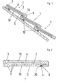
- FIG. 1 shows several roofing elements 1 which overlap one another in the manner of conventional roof tiles and are fastened to the roof battens 10 of a roof.
- the roofing elements have inside a hollow channel 2 with an inlet opening 3 directed against the upper boundary plane 18 and an outlet opening 4 directed against the lower boundary plane 19.
- the inlet and outlet openings abut one another in such a way that a continuous channel system is created.
- a heat transfer liquid is supplied to this channel system from the roof ridge, not shown. This flows downwards without overpressure and heats up as a result of the sun's rays falling on the roof or the ambient heat.
- the entry and exit openings are arranged in such a way that the liquid can flow downward under the action of gravity.
- the heated transmission fluid is collected again with a collecting device, not shown, and fed, for example, to a heat pump. After the energy stored in the liquid has been withdrawn, the transmission liquid is pumped back to the top of the roof in order to run through the channel system again.
- the roofing element consists of a lower half 5 and an upper half 6 with different thermal properties.
- the lower half 5 has poor thermal conductivity and acts as an insulator, which can be achieved, for example, with cavities 7 which are distributed over the entire lower half.
- the upper half 6 has good conductivity, which can be achieved by adding suitable materials.
- the hollow channel 2 is arranged in the upper half 6, so that the liquid only comes into contact with the thermally highly conductive material half.
- the diameter of the inlet opening 3 is advantageously larger than the diameter of the outlet opening 4.
- the outlet opening 4 is also arranged in a slightly protruding nose 8. The nose 8 projects into the inlet opening 3 below, so that a safe transition of the liquid from element to element is ensured.
- the diameter of the nose 8 is advantageously chosen to be somewhat smaller than the diameter of the inlet opening 3, so that the nose has some play and can move freely when the elements are shifted, for example under snow load.
- the cross-section of the inlet and outlet openings is also selected so that no disturbing splashing noises can occur.
- a flow restrictor 20 is arranged in the region of the outlet opening 4, which causes the hollow channel 2 to always remain filled and the flow along the inner wall not to tear off. The dimensioning of the flow restrictor depending on pressure, quantity and flow resistance in the hollow channel is the subject man easily possible and is therefore not described here.
- FIG. 3 shows roofing elements 1, which are arranged in a cross layer.
- the elements each have two approximately parallel hollow channels 2, which are arranged such that a right channel 11 of an upper element opens into a left channel 12 of a lower element.
- the hollow channels are also arranged in a zigzag shape.
- a thermally highly conductive intermediate layer 21 is arranged between the two halves 5 and 6.
- the walls of the hollow channels 2 are surrounded on all sides by good heat-conducting material.
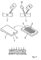
- different starting materials 13 and 14 are used for the two halves of the roofing element.
- a readily combustible or fusible substance 15 is added to the starting material 13 for the lower half.
- a substance 16 which increases the thermal conductivity is added to the starting material 14 for the upper half exposed to the sun's rays.
- Color pigments 17 are also advantageously added, which additionally increase the absorbency.
- the halves are pressed as preforms from the two starting materials, the outlet openings 4 being pressed in the lower half 5 and the inlet openings 3 and the hollow channels 2 being pressed in the upper half 6.
- the two halves 5 and 6 are then placed on top of one another and sintered under the action of pressure and heat.
- the two halves bake together to form a compact unit and form a stable roof tile that has hollow channels on the inside and is provided with inlet and outlet openings.
- the admixture 15 also melts, burns or evaporates in the lower half, so that a porous structure rich in voids is formed in the lower half.
Landscapes
- Engineering & Computer Science (AREA)
- Architecture (AREA)
- Civil Engineering (AREA)
- Structural Engineering (AREA)
- Physics & Mathematics (AREA)
- Life Sciences & Earth Sciences (AREA)
- Sustainable Development (AREA)
- Sustainable Energy (AREA)
- Thermal Sciences (AREA)
- Chemical & Material Sciences (AREA)
- Combustion & Propulsion (AREA)
- Mechanical Engineering (AREA)
- General Engineering & Computer Science (AREA)
- Building Environments (AREA)
- Roof Covering Using Slabs Or Stiff Sheets (AREA)
Applications Claiming Priority (2)
| Application Number | Priority Date | Filing Date | Title |
|---|---|---|---|
| CH558080 | 1980-07-22 | ||
| CH5580/80 | 1980-07-22 |
Publications (1)
| Publication Number | Publication Date |
|---|---|
| EP0044811A1 true EP0044811A1 (fr) | 1982-01-27 |
Family
ID=4295956
Family Applications (1)
| Application Number | Title | Priority Date | Filing Date |
|---|---|---|---|
| EP81810287A Withdrawn EP0044811A1 (fr) | 1980-07-22 | 1981-07-16 | Elément de couverture pour le transport d'un liquide échangeur de chaleur et son procédé de construction |
Country Status (1)
| Country | Link |
|---|---|
| EP (1) | EP0044811A1 (fr) |
Cited By (5)
| Publication number | Priority date | Publication date | Assignee | Title |
|---|---|---|---|---|
| EP0348822A1 (fr) * | 1988-06-30 | 1990-01-03 | Heinz Wacker | Couverture de toit composée par des panneaux de recouvrement se chevauchant longitudinalement et transversalement |
| FR2689157A1 (fr) * | 1992-03-31 | 1993-10-01 | Entre Prises | Tuile à captation solaire. |
| EP1128135A3 (fr) * | 2000-02-24 | 2003-11-26 | Schaller, Joachim, Prof. Dr.-Ing. habil. | Tuile creuse pour la préparation d'eau chaude |
| CN100392330C (zh) * | 2004-09-16 | 2008-06-04 | 杨家华 | 采集太阳能的方法及其加热装置 |
| US9927524B2 (en) | 2010-09-17 | 2018-03-27 | Iee International Electronics & Engineering S.A. | Lidar imager |
Citations (9)
| Publication number | Priority date | Publication date | Assignee | Title |
|---|---|---|---|---|
| CH459524A (de) * | 1966-02-08 | 1968-07-15 | Braas & Co Gmbh | Betondachstein |
| DE2529095A1 (de) * | 1975-06-30 | 1977-01-27 | Geb Nirschl Erna Mari Daeumler | Hohles, auf daechern oder anderen sonnenbestrahlten flaechen anbringbares plattenelement |
| DE2604019A1 (de) * | 1976-02-03 | 1977-08-11 | Philips Patentverwaltung | Selektiver absorber fuer strahlung aus dem bereich des sonnenspektrums |
| FR2364414A1 (fr) * | 1976-09-14 | 1978-04-07 | Bergeon Et Cie | Dispositif pour le captage de l'energie solaire |
| FR2383403A1 (fr) * | 1977-03-11 | 1978-10-06 | Rolland Alain De | Ardoises, tuiles, carrelages scolaires |
| DE2724933A1 (de) * | 1977-06-02 | 1978-12-07 | Schneider Gmbh & Co | Dachziegel und verfahren zu seiner herstellung |
| FR2399631A1 (fr) * | 1977-08-01 | 1979-03-02 | Euratom | Elements modulaires en forme de tuiles ayant fonction de capteurs d'energie solaire |
| FR2421348A1 (fr) * | 1978-03-28 | 1979-10-26 | Legros Jean | Dispositif de tuile constituant un capteur solaire |
| DE2820536A1 (de) * | 1978-05-11 | 1979-11-15 | Werner Dick | Solar-kollektor-dachziegel |
-
1981
- 1981-07-16 EP EP81810287A patent/EP0044811A1/fr not_active Withdrawn
Patent Citations (9)
| Publication number | Priority date | Publication date | Assignee | Title |
|---|---|---|---|---|
| CH459524A (de) * | 1966-02-08 | 1968-07-15 | Braas & Co Gmbh | Betondachstein |
| DE2529095A1 (de) * | 1975-06-30 | 1977-01-27 | Geb Nirschl Erna Mari Daeumler | Hohles, auf daechern oder anderen sonnenbestrahlten flaechen anbringbares plattenelement |
| DE2604019A1 (de) * | 1976-02-03 | 1977-08-11 | Philips Patentverwaltung | Selektiver absorber fuer strahlung aus dem bereich des sonnenspektrums |
| FR2364414A1 (fr) * | 1976-09-14 | 1978-04-07 | Bergeon Et Cie | Dispositif pour le captage de l'energie solaire |
| FR2383403A1 (fr) * | 1977-03-11 | 1978-10-06 | Rolland Alain De | Ardoises, tuiles, carrelages scolaires |
| DE2724933A1 (de) * | 1977-06-02 | 1978-12-07 | Schneider Gmbh & Co | Dachziegel und verfahren zu seiner herstellung |
| FR2399631A1 (fr) * | 1977-08-01 | 1979-03-02 | Euratom | Elements modulaires en forme de tuiles ayant fonction de capteurs d'energie solaire |
| FR2421348A1 (fr) * | 1978-03-28 | 1979-10-26 | Legros Jean | Dispositif de tuile constituant un capteur solaire |
| DE2820536A1 (de) * | 1978-05-11 | 1979-11-15 | Werner Dick | Solar-kollektor-dachziegel |
Cited By (5)
| Publication number | Priority date | Publication date | Assignee | Title |
|---|---|---|---|---|
| EP0348822A1 (fr) * | 1988-06-30 | 1990-01-03 | Heinz Wacker | Couverture de toit composée par des panneaux de recouvrement se chevauchant longitudinalement et transversalement |
| FR2689157A1 (fr) * | 1992-03-31 | 1993-10-01 | Entre Prises | Tuile à captation solaire. |
| EP1128135A3 (fr) * | 2000-02-24 | 2003-11-26 | Schaller, Joachim, Prof. Dr.-Ing. habil. | Tuile creuse pour la préparation d'eau chaude |
| CN100392330C (zh) * | 2004-09-16 | 2008-06-04 | 杨家华 | 采集太阳能的方法及其加热装置 |
| US9927524B2 (en) | 2010-09-17 | 2018-03-27 | Iee International Electronics & Engineering S.A. | Lidar imager |
Similar Documents
| Publication | Publication Date | Title |
|---|---|---|
| DE2811829A1 (de) | Dachbelag | |
| DE2607740A1 (de) | Sammler fuer sonnenenergie | |
| DE2529095C2 (de) | Plattenelement für Dächer und andere sonnenbestrahlte Flächen zum Gewinnen der einstrahlenden Sonnenenergie | |
| DE69112209T2 (de) | Verbesserung für dächer mit solarwärmekollektor. | |
| DE69217654T2 (de) | Temperaturregulierung verschiedener gebäudeteile des hauses | |
| EP0044811A1 (fr) | Elément de couverture pour le transport d'un liquide échangeur de chaleur et son procédé de construction | |
| DE2818475A1 (de) | Dachziegel und dazugehoerige anordnung fuer die gewinnung der sonnenenergie | |
| DE831596C (de) | Raumtemperierungsanlage | |
| CH665870A5 (de) | Fassadenverkleidung an einem gebaeude. | |
| DE3032163A1 (de) | Flaechenheizvorrichtung fuer einen fussboden, sowie estrichwerkstoff hierfuer und verfahren zu dessen herstellung | |
| DE2802682A1 (de) | Dachziegel und zugehoerige anordnung fuer die gewinnung der sonnenenergie | |
| DE2939768A1 (de) | Bauelement, insbesondere fuer wandkonstruktionen, und ziegel als vorfabrikat zu dessen herstellung | |
| CH671060A5 (fr) | ||
| DE876322C (de) | Waermeisoliertes Gebaeudedach | |
| DE19644317A1 (de) | Wabenverstärkte Baukonstruktion und Verfahren zu deren Herstellung und Transport | |
| CH688449A5 (de) | Zweischaliges Mauerwerk in Waermedaemmbauweise, sowie Ziegel fuer das Vormauerwerk hierfuer. | |
| EP0976886B1 (fr) | Elément de construction pour revêtement de toiture et/ou de façade et son procédé de fabrication | |
| DE4333868C2 (de) | Dachkonstruktion | |
| DE4031614A1 (de) | Gebaeude | |
| DE3210607A1 (de) | Dach aus vorgefertigten betonplatten | |
| AT332078B (de) | Hohlblockstein | |
| DE102015105765B4 (de) | Bodentreppe im in einer Geschossdecke eingebauten Zustand | |
| DE2640539B2 (de) | Beheizbarer Unterboden | |
| DE3238237A1 (de) | Selbsttragendes vorgefertigtes bauelement fuer die herstellung von bedachungen | |
| DE2936015A1 (de) | Solardachanordnung |
Legal Events
| Date | Code | Title | Description |
|---|---|---|---|
| PUAI | Public reference made under article 153(3) epc to a published international application that has entered the european phase |
Free format text: ORIGINAL CODE: 0009012 |
|
| AK | Designated contracting states |
Designated state(s): AT BE CH DE FR GB IT LI LU NL SE |
|
| STAA | Information on the status of an ep patent application or granted ep patent |
Free format text: STATUS: THE APPLICATION IS DEEMED TO BE WITHDRAWN |
|
| 18D | Application deemed to be withdrawn |
Effective date: 19830707 |
|
| RIN1 | Information on inventor provided before grant (corrected) |
Inventor name: HEIERLI, WERNER |