EP0044883B1 - Dispositif pour l'ancrage de fils métalliques à des structures au moyen de résines époxydes - Google Patents
Dispositif pour l'ancrage de fils métalliques à des structures au moyen de résines époxydes Download PDFInfo
- Publication number
- EP0044883B1 EP0044883B1 EP80106457A EP80106457A EP0044883B1 EP 0044883 B1 EP0044883 B1 EP 0044883B1 EP 80106457 A EP80106457 A EP 80106457A EP 80106457 A EP80106457 A EP 80106457A EP 0044883 B1 EP0044883 B1 EP 0044883B1
- Authority
- EP
- European Patent Office
- Prior art keywords
- tensioning elements
- tubes
- box
- strand
- concrete structure
- Prior art date
- Legal status (The legal status is an assumption and is not a legal conclusion. Google has not performed a legal analysis and makes no representation as to the accuracy of the status listed.)
- Expired
Links
- 238000004873 anchoring Methods 0.000 title claims description 14
- 239000003822 epoxy resin Substances 0.000 title claims description 9
- 239000002184 metal Substances 0.000 title claims description 9
- 229920000647 polyepoxide Polymers 0.000 title claims description 9
- 239000004567 concrete Substances 0.000 claims description 30
- 229920005989 resin Polymers 0.000 claims description 8
- 239000011347 resin Substances 0.000 claims description 8
- 239000011372 high-strength concrete Substances 0.000 claims description 2
- 238000010276 construction Methods 0.000 description 4
- 238000010008 shearing Methods 0.000 description 4
- 238000002347 injection Methods 0.000 description 3
- 239000007924 injection Substances 0.000 description 3
- 238000000034 method Methods 0.000 description 3
- 239000011150 reinforced concrete Substances 0.000 description 3
- 238000005266 casting Methods 0.000 description 2
- 238000011161 development Methods 0.000 description 2
- 230000018109 developmental process Effects 0.000 description 2
- LNEPOXFFQSENCJ-UHFFFAOYSA-N haloperidol Chemical compound C1CC(O)(C=2C=CC(Cl)=CC=2)CCN1CCCC(=O)C1=CC=C(F)C=C1 LNEPOXFFQSENCJ-UHFFFAOYSA-N 0.000 description 2
- 238000009434 installation Methods 0.000 description 2
- 239000000463 material Substances 0.000 description 2
- 238000012856 packing Methods 0.000 description 2
- 230000002787 reinforcement Effects 0.000 description 2
- 230000001464 adherent effect Effects 0.000 description 1
- 239000003831 antifriction material Substances 0.000 description 1
- 230000000903 blocking effect Effects 0.000 description 1
- 239000003054 catalyst Substances 0.000 description 1
- 239000011248 coating agent Substances 0.000 description 1
- 238000000576 coating method Methods 0.000 description 1
- 230000006835 compression Effects 0.000 description 1
- 238000007906 compression Methods 0.000 description 1
- 238000005260 corrosion Methods 0.000 description 1
- 230000007797 corrosion Effects 0.000 description 1
- 238000006073 displacement reaction Methods 0.000 description 1
- 230000000694 effects Effects 0.000 description 1
- 238000010438 heat treatment Methods 0.000 description 1
- 239000007769 metal material Substances 0.000 description 1
- 238000012797 qualification Methods 0.000 description 1
- 238000011160 research Methods 0.000 description 1
- 239000000243 solution Substances 0.000 description 1
Images

Classifications
-
- E—FIXED CONSTRUCTIONS
- E04—BUILDING
- E04C—STRUCTURAL ELEMENTS; BUILDING MATERIALS
- E04C5/00—Reinforcing elements, e.g. for concrete; Auxiliary elements therefor
- E04C5/08—Members specially adapted to be used in prestressed constructions
- E04C5/12—Anchoring devices
- E04C5/125—Anchoring devices the tensile members are profiled to ensure the anchorage, e.g. when provided with screw-thread, bulges, corrugations
Definitions
- This application relates to anchoring systems for tensioning elements, such as strands, bundles of metal strands or cables with concrete structures or the like, as in works of civil engineering, for example precompressed reinforced concrete structures, structure anchoring stayings, wind- bracings, etc.
- the prior art anchoring systems between tensioning elements and concrete structures are in most cases friction systems; a first type of anchoring system uses metal wedges blocking any slipping between one or more strands and an anchoring plate; in a second system metal rings are forced about the strand head (in case with the interposition of elements such as springs, coils, etc.) so that such a ring and strand will "seize” and no more relative slipping will occur after forcing.
- FR-A-1 328 971 foresees a device comprising a block of concrete where tubes are imbedded.
- the tensioning elements inserted in these tubes are fixed at their outer end by means of fastening devices. No provision is made for destributing the tension along the extremity of each element. Thus the tension remains constant throughout the element which eventually breaks at the zone where other stresses add up to the tension, that is where the fastening devices are applied.
- the tensioning element for brevity hereinafter merely referred to as "strand" is free, that is not adhering to the concrete (or other structures) along the development thereof.
- the changes in tension therein caused by changes in loads (wind, casual variable factors) are transmitted as such to the anchorage.
- the change in strain is the same as that of the free strand, and a further location very close to said first mentioned location, but at the anchorage area, where the changes in strain are much more complex, due to the simultaneous provision of high strains orthogonal to the strand axis, shearing stresses, and strain concentrations at the contact locations between strand and anchorage.
- FR-A 1.551.829 discloses a device for anchoring a plurality of tensioning elements to a structure comprising tubes capable of receiving the tensioning elements; and also a plate placed at the free end of the tubes for securing the tensioning elements and distributing means for receiving the other end of the tubes.
- Fr-A-1.379.706 proposes to fill up a space with epoxy resin containing the strands. In this case the most dangerous zone becomes that corresponding to where each strand leaves the space where epoxy resin is contained. So no complete solution has been reached yet.
- the aim a) and b) is achieved by claim 1, while the additional aims c) and d) are achieved by claim 2 and 3 relating to further preferred developments of the device of claim 1.
- anchorages are provided between strands and structures, in which an improved load condition is obtained in the strand (avoiding strain concentrations and reducing the fatigue phenomena); the strength characteristics of the materials are better taken advantage of with respect to the anchorages of the prior art; and accordingly the total carrying section of the strands can be reduced for a same stress; moreover, the tensioning process can be easily carried out and does not require any particular skill.
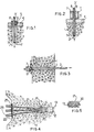
- Fig. 1 shows a concrete structure 1 having a sheath 2 for the passage of strand 3 therethrough. The latter is accommodated with clearance within said sheath 2 and anchored to said structure 1 by a load distributing plate 4 shaped with a countersunk or flared hole 5.
- Three or more wedge elements 6 are arranged about the head 3' of said strand 3 and have the surfaces facing said strand suitable not to slide thereon. When the strand has applied thereto an axial force outline by the arrow shown in Fig. 1, said wedge elements 6 move near one another by contact with the walls of hole 5 and clamp said strand 3 therebetween.
- reference numeral 1 still designates the concrete structure and reference numeral 3 designates the strand as freely accommodated within said sheath 2.
- the load distributing plate 4 has a hole 5' for the passage of the strand head 3' and about said strand head a metal ring 7 is forced with the interposition of a spring 8 between said ring and strand.
- the strand (or in other cases the bundle of strands) is/are free, that is to say not adherent to the concrete in its length.
- the change in strain at A is equal to the change in strain in the free strand.
- the changes in strain are very complex, as above mentioned, due to the simultaneous presence of high strains orthogonal to the strand axis, shearing stresses and strain concentrations at the contact location between said strand and anchorage.
- FIG. 4 A first embodiment of an anchorage according to the present invention is shown in Figs. 4 and 5.
- a sheath 12 freely receives a bundle of strands shown by broken line and carrying the reference numeral 13.
- the concrete structure incorporates a box-like element, designated as a whole at 20, which has open or perforated opposite bases and is of sufficient inner size for the passage of said strands 13 without any contact with the walls, and further has an outer configuration for preventing the box from sliding relative to the concrete.
- said box 20 has a substantially frustoconical or truncated pyramid shape; other boxes could be cylindrical, but have a corrugated surface.
- said box 20 is generally made of metal sheet.
- the concrete structure further incorporates a bundle of tube-like elements 21, generally but not necessarily one for each strand, arranged between said box 20 and the concrete surface 22.
- Each of said tubes 21 have an inner diameter slightly larger than the diameter of strand 13 and have a corrugated surface, as best shown in Fig. 5, such a corrugation of the surface being at the outside in order to promote adherence to the concrete and at the inside in order to promote adherence to a packing with epoxy resins, as hereinafter explained.
- the novel anchorage also comprises a load distributing plate 25, conventionally perforated to receive the ends of strands 13 exiting from said tubes 21, which ends are clamped to the plate in any known manner or by any conventional means, such as those shown in Figs. 1 and 2. Such means have not been shown in detail and are designated by reference numeral 26.
- the novel anchorage further comprise a packing of epoxy resin, generally carried out by injection and shown at 30, about the strands in said tubes and box.
- the shape taken by the resin on filling up the prearranged free spaces or gap is such that a larger mass of resin exists at the side where the strands gather and then proceed at free state (that is in the box), whereas the resin mass is more finely distributed about the strand at the side where the strands join the anchoring plate (tubes).
- the epoxy resins used for injection are of the type at present commercially available, and having the following characteristics:
- a coating or lining of antifriction material has been provided on the inner face of the tubes at the sections of major curvature thereof, so as to allow a good slipping for the strand in case of contact.
- the above described device or assembly for the anchorage of a bundle of strands could also be used for anchorage of a cable.
- the cable distribution of the various strands or wires comprising it is carried out within the box (for example, the box 20 of Fig. 4).
- the individual separated strands or wires then proceed in the tubes, such as 21 of Fig. 4, to reach the anchorages 26, just as shown and described in Fig. 4.
- the novel anchorage is carried out by preassembling said box 20 with said tubes 21 and plate 25 and placing the assembly together with the reinforcement 11' in the caisson intended to receive said concrete structure 1.
- the concrete is then cast and cured.
- the strands may be threaded into the box and tubes at the preassembling step, or after casting and curing of the concrete.
- the required pretension may be applied thereto.
- the epoxy resin is injected by per se well known techniques to fill up the spaces or gaps within said tubes 21 and box 20.
- the clamping means (such as wedges, ring, etc.) 26 transmit to the metal plate 25 (and the latter to concrete) the whole amount of initial pretension to which the strands are subjected. They also transmit the changes in tension successively occurring in the strand at the plate level. However, it should be noted that they are a very small amount of the changes in tension occurring in the free strand, that is at the side opposite to anchorage.
- the box 20 transmits a large amount of the tension of the free strand to concrete, essentially biasing to shearing effect the resin with which it is filled up. It should be noted that considerable relative displacements will occur also between the box walls integral with the concrete and strand; therefore no direct contact should arise between the latter and the rigid walls of the box. Should this occur, a particular fatigue phenomenon of the strand, commonly referred to as “fretting corrosion” or fretting fatigue, would be developed.
- the resin filling up said tubes 21 will reduce almost to zero the relative movements between the strand and concrete, thus resulting in reduction almost to zero for the change in tension in the strand at the plate level and reduction of the fretting fatigue between said strand and inner wall of the tube.
- FIG. 6 A second embodiment of the invention is shown in Fig. 6, in which strands 13 are shown as anchored in a per se known manner by devices, generally designated by reference numeral 26, to a load distributing plate 45.
- a strong box 40 of metal material which has a front flange 41 and a side screw thread 42, on which a ring nut 43 is screwed down, the latter transmitting the strain to said plate 45 which transfers the loads onto the concrete structure 11.
- Said box 40 has tubes 21 exiting therefrom, but in this case said tubes are incorporated in a separate block 50 of very high strength concrete rather than in said concrete 11.
- This embodiment would both provide for adjustment by operating a jack between said flange 41 and plate 45, so as to remove any strain between said ring nut 43 and plate 45, then screwing down said screw nut 43 to the desired position and releasing the jack so that the strain is released through said ring nut 43 onto said plate 45.
- This structure can also be completely replaced in that, without breaking the concrete 11 of the main casting, the strands 13 can be cut, so that both said box 40 and block 50 along with any thing contained therein can be removed and replaced with other new elements.
Landscapes
- Engineering & Computer Science (AREA)
- Architecture (AREA)
- Civil Engineering (AREA)
- Structural Engineering (AREA)
- Reinforcement Elements For Buildings (AREA)
- Piles And Underground Anchors (AREA)
Claims (3)
caractérisé par le fait que:
Applications Claiming Priority (2)
| Application Number | Priority Date | Filing Date | Title |
|---|---|---|---|
| IT23774/80A IT1198345B (it) | 1980-07-29 | 1980-07-29 | Dispositivo e procedimento per eseguire l'ancoraggio tra trefoli metallici e strutture in generale per mezzo di resine epossidiche |
| IT2377480 | 1980-07-29 |
Publications (3)
| Publication Number | Publication Date |
|---|---|
| EP0044883A2 EP0044883A2 (fr) | 1982-02-03 |
| EP0044883A3 EP0044883A3 (en) | 1982-07-28 |
| EP0044883B1 true EP0044883B1 (fr) | 1986-08-27 |
Family
ID=11209858
Family Applications (1)
| Application Number | Title | Priority Date | Filing Date |
|---|---|---|---|
| EP80106457A Expired EP0044883B1 (fr) | 1980-07-29 | 1980-10-23 | Dispositif pour l'ancrage de fils métalliques à des structures au moyen de résines époxydes |
Country Status (6)
| Country | Link |
|---|---|
| EP (1) | EP0044883B1 (fr) |
| AR (1) | AR224037A1 (fr) |
| BR (1) | BR8007663A (fr) |
| DE (1) | DE3071726D1 (fr) |
| ES (1) | ES502743A0 (fr) |
| IT (1) | IT1198345B (fr) |
Families Citing this family (1)
| Publication number | Priority date | Publication date | Assignee | Title |
|---|---|---|---|---|
| CN105401697B (zh) * | 2015-12-08 | 2017-11-28 | 天津市力胜通预应力工程有限公司 | 一种预应力钢绞线锚固件 |
Family Cites Families (5)
| Publication number | Priority date | Publication date | Assignee | Title |
|---|---|---|---|---|
| FR1328971A (fr) * | 1962-04-21 | 1963-06-07 | Stup Procedes Freyssinet | Dispositif de mise en tension et d'ancrage de câbles de précontrainte formés d'ungrand nombre de fils ou de torons |
| FR1379706A (fr) * | 1963-09-26 | 1964-11-27 | Carves Simon Ltd | Dispositif d'ancrage de câbles perfectionné |
| DE1684393A1 (de) * | 1967-02-08 | 1971-04-08 | Paul & Soehne Maschinenfabrik | Spannglied-Anordnung fuer Spannbetonkonstruktionen |
| GB1216343A (en) * | 1967-10-05 | 1970-12-16 | Ccl Systems Ltd | Improvements in or relating to a method and means for anchoring prestressing cables |
| FR2118861B3 (fr) * | 1970-12-24 | 1973-08-10 | Soc Gen Entreprises |
-
1980
- 1980-07-29 IT IT23774/80A patent/IT1198345B/it active
- 1980-10-23 EP EP80106457A patent/EP0044883B1/fr not_active Expired
- 1980-10-23 DE DE8080106457T patent/DE3071726D1/de not_active Expired
- 1980-11-07 AR AR283168A patent/AR224037A1/es active
- 1980-11-10 ES ES502743A patent/ES502743A0/es active Granted
- 1980-11-21 BR BR8007663A patent/BR8007663A/pt unknown
Also Published As
| Publication number | Publication date |
|---|---|
| AR224037A1 (es) | 1981-10-15 |
| IT8023774A0 (it) | 1980-07-29 |
| DE3071726D1 (en) | 1986-10-02 |
| ES8204093A1 (es) | 1982-04-01 |
| IT1198345B (it) | 1988-12-21 |
| EP0044883A3 (en) | 1982-07-28 |
| BR8007663A (pt) | 1982-07-27 |
| ES502743A0 (es) | 1982-04-01 |
| EP0044883A2 (fr) | 1982-02-03 |
Similar Documents
| Publication | Publication Date | Title |
|---|---|---|
| US4442646A (en) | Device for anchoring tensioning elements | |
| US6715176B2 (en) | Device and method for fixing together a construction element and structural cable | |
| EP1629154B9 (fr) | Procede d'ancrage de cables metalliques paralleles | |
| KR100671437B1 (ko) | 지반 앵커리지 | |
| US4640068A (en) | Anchoring and coupling device for tendons in prestressed concrete | |
| US4594827A (en) | Tension member, particularly for use as a diagonal cable in a stayed girder bridge | |
| JP3917369B2 (ja) | ケーブルに荷重伝達部材を取り付ける方法及び装置並びに該装置を備えた吊り橋 | |
| US2737802A (en) | Composite prestressing reinforcement | |
| US5024032A (en) | Post-tensioning anchor | |
| US4977715A (en) | Reinforced-concrete building element | |
| KR101346344B1 (ko) | 콘크리트 내부에 긴장재 고정 정착부를 구비한 비부착식 psc i 빔 및 그 제조 방법 | |
| US6487757B1 (en) | System for connecting a structural cable to a building work structure | |
| EP4118360B1 (fr) | Agencement de limitation de courbure de câble et combinaison d'un agencement de limitation de courbure de câble avec un câble, un ancrage, une unité pince de compactage et un tuyau creux | |
| US9315998B1 (en) | Cable lock-off block for repairing a plurality of post-tensioned tendons | |
| EP4265863A1 (fr) | Outil de fixation et béton précontraint | |
| JPH07189427A (ja) | Frp補強材の端末定着構造 | |
| EP0044883B1 (fr) | Dispositif pour l'ancrage de fils métalliques à des structures au moyen de résines époxydes | |
| GB2255354A (en) | Strand anchorage | |
| JPH11323823A (ja) | 建設構造物用の吊り下げ装置 | |
| US4538940A (en) | Arrangement for force transfer between longitudinally stressed members | |
| KR200494644Y1 (ko) | 강연선 클램핑용 더미 구조체 | |
| WO1998006913A1 (fr) | Fabrication de structures en beton | |
| JP2023155566A (ja) | 緊張材の定着構造およびプレストレストコンクリート構造物の製作方法 | |
| KR100912365B1 (ko) | 분절가능한 프리스트레스 콘크리트 부재 | |
| HK1035220B (en) | Ground anchorage |
Legal Events
| Date | Code | Title | Description |
|---|---|---|---|
| PUAI | Public reference made under article 153(3) epc to a published international application that has entered the european phase |
Free format text: ORIGINAL CODE: 0009012 |
|
| AK | Designated contracting states |
Designated state(s): CH DE FR GB |
|
| PUAL | Search report despatched |
Free format text: ORIGINAL CODE: 0009013 |
|
| AK | Designated contracting states |
Designated state(s): CH DE FR GB |
|
| 17P | Request for examination filed |
Effective date: 19821230 |
|
| GRAA | (expected) grant |
Free format text: ORIGINAL CODE: 0009210 |
|
| AK | Designated contracting states |
Kind code of ref document: B1 Designated state(s): CH DE FR GB LI |
|
| REF | Corresponds to: |
Ref document number: 3071726 Country of ref document: DE Date of ref document: 19861002 |
|
| ET | Fr: translation filed | ||
| PLBE | No opposition filed within time limit |
Free format text: ORIGINAL CODE: 0009261 |
|
| STAA | Information on the status of an ep patent application or granted ep patent |
Free format text: STATUS: NO OPPOSITION FILED WITHIN TIME LIMIT |
|
| 26N | No opposition filed | ||
| PGFP | Annual fee paid to national office [announced via postgrant information from national office to epo] |
Ref country code: FR Payment date: 19921028 Year of fee payment: 13 Ref country code: CH Payment date: 19921028 Year of fee payment: 13 |
|
| PGFP | Annual fee paid to national office [announced via postgrant information from national office to epo] |
Ref country code: GB Payment date: 19921102 Year of fee payment: 13 |
|
| PGFP | Annual fee paid to national office [announced via postgrant information from national office to epo] |
Ref country code: DE Payment date: 19921216 Year of fee payment: 13 |
|
| PG25 | Lapsed in a contracting state [announced via postgrant information from national office to epo] |
Ref country code: GB Effective date: 19931023 |
|
| PG25 | Lapsed in a contracting state [announced via postgrant information from national office to epo] |
Ref country code: LI Effective date: 19931031 Ref country code: CH Effective date: 19931031 |
|
| GBPC | Gb: european patent ceased through non-payment of renewal fee |
Effective date: 19931023 |
|
| PG25 | Lapsed in a contracting state [announced via postgrant information from national office to epo] |
Ref country code: FR Effective date: 19940630 |
|
| REG | Reference to a national code |
Ref country code: CH Ref legal event code: PL |
|
| PG25 | Lapsed in a contracting state [announced via postgrant information from national office to epo] |
Ref country code: DE Effective date: 19940701 |
|
| REG | Reference to a national code |
Ref country code: FR Ref legal event code: ST |