EP0044896A1 - Vorrichtung zum Erstellen einer Gebäudewand aus Bausteinen - Google Patents
Vorrichtung zum Erstellen einer Gebäudewand aus Bausteinen Download PDFInfo
- Publication number
- EP0044896A1 EP0044896A1 EP80401117A EP80401117A EP0044896A1 EP 0044896 A1 EP0044896 A1 EP 0044896A1 EP 80401117 A EP80401117 A EP 80401117A EP 80401117 A EP80401117 A EP 80401117A EP 0044896 A1 EP0044896 A1 EP 0044896A1
- Authority
- EP
- European Patent Office
- Prior art keywords
- vertical
- guide
- panels
- formwork
- elements
- Prior art date
- Legal status (The legal status is an assumption and is not a legal conclusion. Google has not performed a legal analysis and makes no representation as to the accuracy of the status listed.)
- Withdrawn
Links
- 238000009415 formwork Methods 0.000 claims abstract description 73
- 239000011449 brick Substances 0.000 claims abstract description 6
- 230000000284 resting effect Effects 0.000 claims abstract 3
- 238000009416 shuttering Methods 0.000 claims description 14
- 238000004873 anchoring Methods 0.000 claims description 10
- 239000004570 mortar (masonry) Substances 0.000 claims description 10
- 238000000465 moulding Methods 0.000 claims description 9
- 125000006850 spacer group Chemical group 0.000 claims description 7
- 239000002023 wood Substances 0.000 claims description 6
- 238000009432 framing Methods 0.000 claims description 5
- 239000000463 material Substances 0.000 claims description 5
- 230000000712 assembly Effects 0.000 claims description 3
- 238000000429 assembly Methods 0.000 claims description 3
- 230000000295 complement effect Effects 0.000 claims description 2
- 238000010276 construction Methods 0.000 description 15
- 238000009434 installation Methods 0.000 description 4
- 229910052751 metal Inorganic materials 0.000 description 3
- 239000002184 metal Substances 0.000 description 3
- 238000000034 method Methods 0.000 description 3
- 239000011464 hollow brick Substances 0.000 description 2
- 238000004519 manufacturing process Methods 0.000 description 2
- 238000005192 partition Methods 0.000 description 2
- 238000002360 preparation method Methods 0.000 description 2
- 229920002994 synthetic fiber Polymers 0.000 description 2
- CWYNVVGOOAEACU-UHFFFAOYSA-N Fe2+ Chemical compound [Fe+2] CWYNVVGOOAEACU-UHFFFAOYSA-N 0.000 description 1
- 229910000746 Structural steel Inorganic materials 0.000 description 1
- 239000000969 carrier Substances 0.000 description 1
- 239000000470 constituent Substances 0.000 description 1
- 239000011229 interlayer Substances 0.000 description 1
- 229910001234 light alloy Inorganic materials 0.000 description 1
- 229910001095 light aluminium alloy Inorganic materials 0.000 description 1
- 230000002787 reinforcement Effects 0.000 description 1
- 238000007789 sealing Methods 0.000 description 1
- 239000007787 solid Substances 0.000 description 1
- 238000000638 solvent extraction Methods 0.000 description 1
Images




Classifications
-
- E—FIXED CONSTRUCTIONS
- E04—BUILDING
- E04G—SCAFFOLDING; FORMS; SHUTTERING; BUILDING IMPLEMENTS OR AIDS, OR THEIR USE; HANDLING BUILDING MATERIALS ON THE SITE; REPAIRING, BREAKING-UP OR OTHER WORK ON EXISTING BUILDINGS
- E04G21/00—Preparing, conveying, or working-up building materials or building elements in situ; Other devices or measures for constructional work
- E04G21/14—Conveying or assembling building elements
- E04G21/16—Tools or apparatus
- E04G21/20—Tools or apparatus for applying mortar
-
- E—FIXED CONSTRUCTIONS
- E04—BUILDING
- E04G—SCAFFOLDING; FORMS; SHUTTERING; BUILDING IMPLEMENTS OR AIDS, OR THEIR USE; HANDLING BUILDING MATERIALS ON THE SITE; REPAIRING, BREAKING-UP OR OTHER WORK ON EXISTING BUILDINGS
- E04G21/00—Preparing, conveying, or working-up building materials or building elements in situ; Other devices or measures for constructional work
- E04G21/14—Conveying or assembling building elements
- E04G21/16—Tools or apparatus
- E04G21/18—Adjusting tools; Templates
- E04G21/1841—Means for positioning building parts or elements
- E04G21/1858—Templates for window or door openings, e.g. in a masonry wall
Definitions
- the invention relates to an apparatus for realizing building masonry comprising concrete posts and walls made of building blocks such as hollow bricks, solid bricks, concrete blocks ...
- each of the rows of building blocks is horizontal, which implies that the interlayers of mortar are of equal thickness from one end to the other of the wall.
- the concrete posts are generally shuttered by means of pieces of wood assembled by nailing and the preparation of these shutters constitutes a long and delicate operation.
- An objective of the invention is to eliminate these drawbacks and to provide an apparatus making it possible to produce, at the same time, the walls, partitions, and posts of a construction.
- the vertical formwork elements are first fixed on the building infrastructure according to the location of the posts to be provided.
- the means for fixing these shuttering elements may advantageously include tie rods of adjustable length, which are connected to said elements and make it possible to adjust the verticality thereof, and anchoring parts suitable for being embedded in the infrastructure at the time of realization thereof; these anchoring parts allow the fixing, in the lower part, of the tie rods and of the vertical formwork elements on said infrastructure.
- the operator arranges the building guide between two forms, the sliding means making it possible to bring this guide to slide vertically relative to the formwork elements, while the stop means ensure the maintaining the guide at each row of building blocks.
- the above-mentioned sliding means comprise, on the one hand, profiles, fixed vertically at the edge of the vertical shuttering elements and provided with a guide rebate, on the other hand, slides carried laterally by the panels of the building guide and adapted to engage and slide in the aforementioned rebates.
- stop means may advantageously comprise, on the one hand, a plurality of support pieces fixed at adjustable height at the bottom of the rebates of the profiles subject to the vertical shuttering elements, on the other hand, an associated retractable cleat to elastic means and carried by each end of each panel of the guide
- each retractable cleat being provided with a horizontal lower flank allowing it to rest on a support piece and an upper flank at an angle allowing it to retract during an upward movement.
- the panels of the guide to be built have a height slightly greater than the height of a building block increased by the thickness of the two horizontal joints to be produced between blocks.
- the building guide is then moved vertically after completion of each row; for each of them, it serves, on the one hand, as a formwork for the mortar bed poured on the previous row, on the other hand, as a guide for the establishment of building blocks, then as formwork for the joints vertical between bricks, finally formwork for the upper mortar bed above which the next row will be placed. Once these operations have been completed, the guide is moved to build a new row.
- the switchgear can be used in two ways.
- each additional formwork has a shaped section. of U and is arranged to be fixed in a horizontal direction with adjustable height between two vertical bay forms.
- each box has a thickness substantially equal to the distance separating the two panels in order to be disposed between them to form a stop guide at the edge of the bay.
- the two ways of operating can be combined, the building blocks being stopped at an edge of the opening by a box and at the other edge, by a vertical framing formwork.
- each vertical formwork element and each panel of the building guide have a similar sandwich structure, composed of a core covered with two surface plates and bordered, on a longitudinal edge, by a profile forming an internal housing opening on one face of the element and, on the other longitudinal edge, of another profile forming, on the one hand, an internal housing opening on one face of the element, on the other hand, a rebate opening on the edge of the element.
- each element or panel is advantageously made of a wood-based material, the surface plates being formed by laminated sheets of a wood-based material; the profiles can be metallic for example light alloy or ferrous metal. Of course, other materials can be used and in particular synthetic materials.
- the apparatus is completed by junction assemblies allowing the assembly of several formwork elements or guide panels, either end to end, or at 90 °; each junction assembly comprises an internal retaining part capable of fitting into the rebate or the internal housing of the profiles, an external connecting part capable of ensuring the connection between the elements or panels to be assembled and means for clamping the parts support and connecting piece.
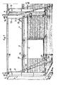
- this apparatus essentially comprises a building guide 1, capable of sliding vertically, by means which will be described later, between two vertical column formwork, in the example a corner formwork 2 and a connecting formwork 3 with a cross wall.
- the building guide comprises two parallel panels 4 and 5 arranged in vertical planes and extending in a horizontal direction, while the column forms are composed of vertical elements, such as 6 and 7 for the corner formwork, and 9, 10 and 11 for the intermediate formwork, which are assembled together to form molding volumes adapted to the posts to be poured.
- the panels 4 and 5 of the guide are connected by handles such as 12 which allow them to be maneuvered simultaneously, for example by means of operating means comprising cables such as 13, return pulleys such as 14 and a winch 15 .
- the guide 1 is equipped with two boxes 16 interposed between its two panels, to make an opening.
- Each box 16 is fixed to the panels 4 and 5 of the guide by means of legs in the shape of an inverted U such as 17, welded to said box; these tabs overlap the panels 4 and 5 and are fixed thereon by retaining pieces which cooperate with longitudinal housings 31 which the panels comprise (and which will be described later).
- the vertical elements of the same formwork (2 or 3) are interconnected by spacers such as 18 distributed over their height.
- bracing crosspieces such as 19.
- the elements corresponding to the external face are joined by said sleepers; if necessary, these crosspieces can also be provided between the internal elements of the neighboring forms.
- the vertical forms are fixed to the building infrastructure, on the one hand, at their base by anchoring parts such as 20 embedded in said infrastructure, on the other hand, by tie rods 21 provided with turnbuckles such that 22 to allow the length to be adjusted; these tie rods are themselves fixed at their base to the infrastructure by anchoring parts such as 23.
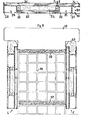
- Figure 2 shows in section the structure of a guide panel to build or a vertical formwork element.
- This structure essentially comprises a wooden core 24, covered by surface plates 25 and 26 formed by laminated wooden sheets; in addition, metal profiles 27 and 28, for example of light aluminum alloy, are fixed on the two longitudinal edges of the element or panel.
- the surface plate 26 completely covers said profiles in order to form a continuous flat face, the core 24 and the other surface plate 25 stopping against said profiles as shown in FIG. 2.
- One of the profiles 27 forms, on the one hand, a rebate 29 opening on the edge of the element with two small returns partially partitioning the bottom of the rebate, on the other hand, an internal housing 31 opening on one face of the element by an opening bordered by two small returns 32.
- the other profile 28 forms an internal housing 33 identical to the housing 31.
- the profiles On the edge of the element, the profiles have wings such as 34 which overlap the edges of the surface plate 26 and protect them; opposite the wings 34, said sections have extensions 35 which protect the edges of the surface plate 25 and allow them to be fixed by countersunk head screws on the panel.
- Figure 3 shows in detail the building guide 1 whose two panels 4 and 5 have the sandwich structure described above. As this figure shows, the height of each panel is slightly greater than the height of a building block (in the example, a hollow brick 36) increased by the thickness of the two horizontal mortar beds 37 and 38 to be produced. .
- a building block in the example, a hollow brick 36
- the building guide is moved vertically to bring it up to a row (36) when the lower bed 37 is produced. Thanks to the above-mentioned height of the guide panels, this still fresh bed 37 remains boxed during the installation of the construction elements of the row 36.
- the upper bed 38 is then produced, by placing the mortar above the row between the upper edges of the panels 4 and 5 and by leveling off the upper surface by means of a squeegee 39 which the operator moves horizontally in abutment on wooden beams 40 inserted in the rebates 29 of the profiles 27.
- a regular bed 38 is thus obtained, of constant thickness, while the faces of the wall, guided and shuttered by the continuous faces of the two panels 4 and 5 of the guide are perfectly flat and vertical.
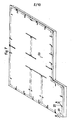
- Figure 4 shows in perspective corner formwork, intermediate formwork, connecting formwork with cross wall and bay frame formwork.
- the elements 6 and 7 of the angle formwork are. composed of two panels assembled at 90 ° as we will see later.
- Each spacer 18 may be constituted by a cylindrical bar fixed at each end by bolts arranged in the internal housings of the formwork elements which are drilled for this purpose. Each bar is surrounded by a sleeve, in particular of synthetic material, which remains in place after the concrete has been poured and which makes it possible to remove the cylindrical bar.
- a sleeve in particular of synthetic material, which remains in place after the concrete has been poured and which makes it possible to remove the cylindrical bar.
- metal spacers intended to remain in the concrete, each composed of two rods provided with a nut at their end, these rods slightly bent in the middle offering the possibility of varying the length of the spacer.
- Connection formwork with cross wall is composed of three vertical elements 9, 10, 11 which define a T-shaped molding volume.
- Elements 10 and 11 are composed of two panels assembled at 90 °. The same system of spacers distributed over the height of the elements ensures a rigid connection between elements.
- FIG. 4 also presents a connecting formwork comprising two vertical planar elements 41 and 42 and a bay framing formwork comprising a vertical element 44 composed of 3 panels assembled at 90 ° to form a rectangular molding volume open on one face .
- Figures 5 and 6 show in section, the corner formwork to illustrate a 90 ° method of assembly of the panels that form it.
- the two panels of the external element 7 are assembled by means of angle brackets 45 which are bolted against the profiles 28 of the panels as shown in the figures.
- the panels of the internal element 6, which are narrower, have only a profile 27 and a surface plate 26 and are assembled in the example by pieces of wood 46 inserted between the wings 35 of the profiles and screwed onto these wings.
- other assembly methods can be used depending on the applications.
- a fixing fitting 47 formed of 3 integral plates, located in orthogonal planes two by two. This fitting 47 is fixed on the profile 27 of each panel of the internal element 6 by means of holding pieces (not shown) inserted in the internal housing of each profile and bolted to the fitting 47.
- the base plate of the fitting is bolted to the anchoring parts already mentioned, which can be seen at 20 in FIGS. 11 and 12.
- These anchoring parts 20 each consisting of a nut secured to a sealing lug are embedded in the floor (or platform) of the construction infrastructure (referenced 50 in these figures); their position is planned in advance according to the location of the posts.
- anchoring parts formed by rails such as 23 are embedded in the floor or platform 50 in order to allow fixing by bolting of the tie-rod feet 21.
- Each rail 23 has a C-shaped section and the bolting of the tie-rod can be carried out in an adjustable position by pinching the horizontal returns that have said rails.
- the external elements of the vertical forms are fixed as shown in Figures 8 and 10, by anchor pieces 56 embedded in the base wall (or possibly in the bottom chaining); these parts 56 allow fixing on the vertical face of this base wall, the lower parts of the external formwork which, for this purpose, extend at the level of this base.
- FIG. 9 shows an anchor piece 43 embedded at the bottom of the top floor chaining in order to play a role similar to that of the pieces 56 in the floors.
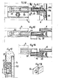
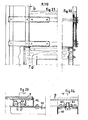
- FIGS. 14, 15, 16, 17. and 18 show the sliding means and stop means between a guide panel 4 and a shuttering element 6.
- the panel 4 is provided with two slide carriers such as 51, one located in the lower part at the level of the profile 28 of the panel, the other in the upper part at the level of the profile 27.
- Each holder slide 51 is mounted in a sheath 52 inserted and fixed in the internal housing of the profile 27 or 28 of the panel.
- a spring 53 is associated with this slide carrier to urge it outwards and give it a projecting position relative to the end edge of the panel 4.
- the slide carrier 51 carries at the end a slide 54, of a shape adapted to be housed in the rebate of the profile of the formwork 6 and a stop cleat 55 fixed in said slide carrier which is hollowed out for this purpose.
- Each cleat is retractable by the play of the elasticity of the spring 53 and is provided with a horizontal lower flank 55a and an upper flank 54b at an angle to allow it to retract.
- the formwork element 6 is further equipped at the bottom of the rebate of its profile with a plurality of support pieces such as 56 fixed by a pressure screw. adjustable height; these parts are previously positioned and fixed by the operator at each row to be produced, depending on the height of the building blocks. They can be biased in the lower part to facilitate the retraction of the cleat 55 when it comes to bear against the support piece.
- each slide 54 and cleat 55 are arranged to be able to have at least two positions offset from one another in the direction of the thickness of the wall in order to allow adjustment of the distance separating the two. panels 4 and 5 of the building guide.
- this offset is allowed by a double housing that comprises the slide holder 51, which allows to have the slide 54 and its cleat 55, either in one of the housings directly in face of profile 27 of panel 4, ( Figure 15) or in the other housing in the offset position ( Figure 16).
- the operator has the possibility of removing the panels 4 and 5 from the guide, either by shifting the slides and stops of one of the guide panels, or by shifting the slides and stops of the two panels if the blocks are oversized.
- FIGS. 19 and 20 illustrate the end-to-end assembly of two guide panels to be built, for example in order to produce a very long wall (without intermediate post).
- Such panel assemblies are carried out by means of internal retaining pieces 57 inserted in the internal housings of the panel profiles, elongated connecting pieces 58 applied to the outside on said sections and clamping screws 59 making it possible to secure these pieces and block the profiles by pinching.
- the ends of the screws 59 are fitted into blind holes provided in said panels at the bottom of the housings of their profiles.
- Figures 21 and 22 illustrate a similar assembly but in which the panels are arranged at 90 °.
- the assembly system is similar, the external connecting pieces being crossed relative to the holding pieces of one of the panels.
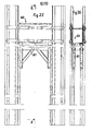
- FIGS 23 and 24 show the assembly of a brace cross 19 on a vertical formwork element 7. This assembly is achieved by means of a retaining piece 62 inserted in the internal housing of the profile of the formwork element 7.
- the brace 19 is formed by two L-shaped profiles arranged in a U with a spacing slightly greater than the diameter of a clamping screw 63. These two profiles are connected by plates welded thereon and distributed over their length.
- the head of the screw 63 provided with a washer allows the tightening of the crosspiece against the profile of the formwork.
- an angle iron 64 is fixed vertically on the crosspiece 19 bearing against the edge of each formwork element 7. This angle serves to adjust the vertical parallelism of the formwork.
- Figures 25 and 26 illustrate the realization of a window frame using the assembly of Figure 21.
- This frame comprises two vertical U-shaped shuttering elements as already described and a horizontal shuttering element 60 of similar section open upwards.
- the panels located in vertical planes are assembled as already described, with the option of adjusting the height of the horizontal formwork element along the vertical elements.
- Reinforcement brackets such as 61 are also provided for holding the horizontal panel of the horizontal formwork element.
Landscapes
- Engineering & Computer Science (AREA)
- Architecture (AREA)
- Mechanical Engineering (AREA)
- Civil Engineering (AREA)
- Structural Engineering (AREA)
- Forms Removed On Construction Sites Or Auxiliary Members Thereof (AREA)
Priority Applications (1)
| Application Number | Priority Date | Filing Date | Title |
|---|---|---|---|
| EP80401117A EP0044896A1 (de) | 1980-07-29 | 1980-07-29 | Vorrichtung zum Erstellen einer Gebäudewand aus Bausteinen |
Applications Claiming Priority (1)
| Application Number | Priority Date | Filing Date | Title |
|---|---|---|---|
| EP80401117A EP0044896A1 (de) | 1980-07-29 | 1980-07-29 | Vorrichtung zum Erstellen einer Gebäudewand aus Bausteinen |
Publications (1)
| Publication Number | Publication Date |
|---|---|
| EP0044896A1 true EP0044896A1 (de) | 1982-02-03 |
Family
ID=8187387
Family Applications (1)
| Application Number | Title | Priority Date | Filing Date |
|---|---|---|---|
| EP80401117A Withdrawn EP0044896A1 (de) | 1980-07-29 | 1980-07-29 | Vorrichtung zum Erstellen einer Gebäudewand aus Bausteinen |
Country Status (1)
| Country | Link |
|---|---|
| EP (1) | EP0044896A1 (de) |
Cited By (7)
| Publication number | Priority date | Publication date | Assignee | Title |
|---|---|---|---|---|
| AU697602B2 (en) * | 1994-07-26 | 1998-10-15 | John Toth | Brick laying apparatus |
| WO2005010298A1 (en) * | 2003-07-23 | 2005-02-03 | Preston Holdings Pty Ltd | Machine for bricklaying |
| GB2422400A (en) * | 2005-01-25 | 2006-07-26 | Edson Da Silva Rosa | Bricklaying apparatus |
| US7495089B2 (en) | 1995-10-23 | 2009-02-24 | The Children's Medical Center Corporation | Therapeutic antiangiogenic endostatin compositions |
| CN113195836A (zh) * | 2018-12-20 | 2021-07-30 | 方思德有限责任公司 | 使用由振动或敲击而嵌入的板材来制造立柱的基础的方法和套件 |
| CN114412050A (zh) * | 2022-02-25 | 2022-04-29 | 浙江亚厦装饰股份有限公司 | 一种装配式吊顶与钢梁连接处的连接件及安装方法 |
| US20250369237A1 (en) * | 2024-06-03 | 2025-12-04 | Dan Mills | Door Trim Installation System And Method Therefor |
Citations (1)
| Publication number | Priority date | Publication date | Assignee | Title |
|---|---|---|---|---|
| DE460542C (de) * | 1924-07-12 | 1928-05-30 | Ludwig Liedler | Schalung |
-
1980
- 1980-07-29 EP EP80401117A patent/EP0044896A1/de not_active Withdrawn
Patent Citations (1)
| Publication number | Priority date | Publication date | Assignee | Title |
|---|---|---|---|---|
| DE460542C (de) * | 1924-07-12 | 1928-05-30 | Ludwig Liedler | Schalung |
Cited By (9)
| Publication number | Priority date | Publication date | Assignee | Title |
|---|---|---|---|---|
| AU697602B2 (en) * | 1994-07-26 | 1998-10-15 | John Toth | Brick laying apparatus |
| US7495089B2 (en) | 1995-10-23 | 2009-02-24 | The Children's Medical Center Corporation | Therapeutic antiangiogenic endostatin compositions |
| US7867975B2 (en) | 1995-10-23 | 2011-01-11 | The Children's Medical Center Corporation | Therapeutic antiangiogenic endostatin compositions |
| WO2005010298A1 (en) * | 2003-07-23 | 2005-02-03 | Preston Holdings Pty Ltd | Machine for bricklaying |
| GB2422400A (en) * | 2005-01-25 | 2006-07-26 | Edson Da Silva Rosa | Bricklaying apparatus |
| CN113195836A (zh) * | 2018-12-20 | 2021-07-30 | 方思德有限责任公司 | 使用由振动或敲击而嵌入的板材来制造立柱的基础的方法和套件 |
| CN113195836B (zh) * | 2018-12-20 | 2023-02-21 | 方思德有限责任公司 | 使用由振动或敲击而嵌入的板材来制造立柱的基础的方法和套件 |
| CN114412050A (zh) * | 2022-02-25 | 2022-04-29 | 浙江亚厦装饰股份有限公司 | 一种装配式吊顶与钢梁连接处的连接件及安装方法 |
| US20250369237A1 (en) * | 2024-06-03 | 2025-12-04 | Dan Mills | Door Trim Installation System And Method Therefor |
Similar Documents
| Publication | Publication Date | Title |
|---|---|---|
| EP0199978A2 (de) | Bauelementensatz zur Errichtung von Bauwerken | |
| EP0017630B1 (de) | Schalungssystem für das Schütten von Mauern oder Wänden aus Beton und Verfahren zum Zusammensetzen dieses Systems | |
| EP3179010A1 (de) | Vertikale verschalung, die eine tür umfasst | |
| FR2664319A1 (fr) | Dispositif de coffrage comportant des panneaux et des pieces de liaison pour assembler ces panneaux. | |
| FR2958873A1 (fr) | Moule de prefabrication transportable | |
| FR2620153A1 (fr) | Panneau de construction, notamment panneau de bardage, a isolation thermique integree | |
| FR2745837A1 (fr) | Un dispositif de contraction de forme pour un montage de forme de plancher | |
| EP0093030B1 (de) | Tiefraum, insbesondere ein Keller und Einrichtungsverfahren desselben | |
| FR2487411A2 (fr) | Appareillage perfectionne pour realiser une maconnerie de batiment a partir de blocs de construction | |
| EP0112199A1 (de) | Rahmen in Öffnungen bestehend aus Metallprofilen mit unterbrochenen Wärmebrücken und Pressgerät für das Bearbeiten dieser Profile | |
| WO2005116355A1 (fr) | Procede de construction d'une maison en bois | |
| FR2590294A1 (fr) | Ensemble con | |
| EP0321321B1 (de) | Gebäude mit vorgefertigten Elementen | |
| FR3096709A1 (fr) | Système de coffrage d’un ensemble comprenant un mur de soutènement, un mur de parement et un soubassement et procédé de coffrage | |
| FR2962475A1 (fr) | Structure de menuiserie a poser au niveau d'une baie de batiment | |
| FR2483981A1 (fr) | Elements modulaires et leur procede d'assemblage pour la construction de maisonnettes notamment en bois | |
| FR2576355A1 (fr) | Coffrage pour la realisation de tunnels | |
| FR2634238A1 (fr) | Elements de construction prefabriques et procede pour la realisation economique de mur isotherme | |
| CH491267A (fr) | Dispositif de coffrage pour mur en béton | |
| FR2650611A1 (fr) | Ossature en bois pour la realisation de murs ou parois d'une construction et construction obtenue a partir de ladite ossature | |
| WO2005017271A2 (fr) | Jeu de panneaux semi-ouverts et manuportables et de pièces de liaison pour construire une maison à ossature bois | |
| FR2578278A1 (fr) | Procede de construction de batiments par assemblage mecanique d'elements de construction prefabriques et elements correspondants | |
| FR2712906A1 (fr) | Procédé d'assemblage d'éléments modulaires préfabriqués et construction résultante. | |
| FR2533959A1 (fr) | Dispositif de bardage rapporte | |
| WO1991006727A1 (fr) | Element de construction standardise modulable et procede d'utilisation |
Legal Events
| Date | Code | Title | Description |
|---|---|---|---|
| PUAI | Public reference made under article 153(3) epc to a published international application that has entered the european phase |
Free format text: ORIGINAL CODE: 0009012 |
|
| AK | Designated contracting states |
Designated state(s): AT BE CH DE GB IT LU NL SE |
|
| STAA | Information on the status of an ep patent application or granted ep patent |
Free format text: STATUS: THE APPLICATION IS DEEMED TO BE WITHDRAWN |
|
| 18D | Application deemed to be withdrawn |
Effective date: 19830111 |