EP0044918A1 - Circuit pour l'établissement et la libération d'une liaison de données - Google Patents
Circuit pour l'établissement et la libération d'une liaison de données Download PDFInfo
- Publication number
- EP0044918A1 EP0044918A1 EP81104055A EP81104055A EP0044918A1 EP 0044918 A1 EP0044918 A1 EP 0044918A1 EP 81104055 A EP81104055 A EP 81104055A EP 81104055 A EP81104055 A EP 81104055A EP 0044918 A1 EP0044918 A1 EP 0044918A1
- Authority
- EP
- European Patent Office
- Prior art keywords
- circuit arrangement
- arrangement according
- line
- connection
- office
- Prior art date
- Legal status (The legal status is an assumption and is not a legal conclusion. Google has not performed a legal analysis and makes no representation as to the accuracy of the status listed.)
- Granted
Links
- 238000004140 cleaning Methods 0.000 title 1
- 230000015654 memory Effects 0.000 claims abstract description 10
- 230000005540 biological transmission Effects 0.000 claims abstract description 8
- 238000012544 monitoring process Methods 0.000 claims abstract 2
- 230000000977 initiatory effect Effects 0.000 claims description 6
- 230000003111 delayed effect Effects 0.000 claims 1
- 238000000034 method Methods 0.000 description 6
- 239000003990 capacitor Substances 0.000 description 5
- 238000004088 simulation Methods 0.000 description 3
- 230000006870 function Effects 0.000 description 2
- 239000004065 semiconductor Substances 0.000 description 2
- 230000015556 catabolic process Effects 0.000 description 1
- 238000010586 diagram Methods 0.000 description 1
- 238000004146 energy storage Methods 0.000 description 1
- 230000005284 excitation Effects 0.000 description 1
- 230000005669 field effect Effects 0.000 description 1
- 238000002955 isolation Methods 0.000 description 1
- 230000007257 malfunction Effects 0.000 description 1
- 239000011159 matrix material Substances 0.000 description 1
- 210000000056 organ Anatomy 0.000 description 1
- 230000001960 triggered effect Effects 0.000 description 1
Images

Classifications
-
- H—ELECTRICITY
- H04—ELECTRIC COMMUNICATION TECHNIQUE
- H04M—TELEPHONIC COMMUNICATION
- H04M1/00—Substation equipment, e.g. for use by subscribers
- H04M1/26—Devices for calling a subscriber
- H04M1/27—Devices whereby a plurality of signals may be stored simultaneously
- H04M1/272—Devices whereby a plurality of signals may be stored simultaneously with provision for storing only one subscriber number at a time, e.g. by keyboard or dial
- H04M1/2725—Devices whereby a plurality of signals may be stored simultaneously with provision for storing only one subscriber number at a time, e.g. by keyboard or dial using electronic memories
-
- H—ELECTRICITY
- H04—ELECTRIC COMMUNICATION TECHNIQUE
- H04M—TELEPHONIC COMMUNICATION
- H04M11/00—Telephonic communication systems specially adapted for combination with other electrical systems
- H04M11/06—Simultaneous speech and data transmission, e.g. telegraphic transmission over the same conductors
-
- H—ELECTRICITY
- H04—ELECTRIC COMMUNICATION TECHNIQUE
- H04M—TELEPHONIC COMMUNICATION
- H04M11/00—Telephonic communication systems specially adapted for combination with other electrical systems
- H04M11/08—Telephonic communication systems specially adapted for combination with other electrical systems specially adapted for optional reception of entertainment or informative matter
- H04M11/085—Telephonic communication systems specially adapted for combination with other electrical systems specially adapted for optional reception of entertainment or informative matter using a television receiver, e.g. viewdata system
Definitions
- the invention relates to a circuit arrangement for setting up or clearing down a connection with the aid of a data transmission device according to the preamble of the main claim.
- Such screen text modems which are provided with an automatic dialing device, together with a television set which is set up for screen text reception, allow the owner or user of a telephone connection to consume the new service screen text via his telephone connection line, whereby telephone and screen text reception are only possible.
- the on-screen text modems have to have a mains-independent power supply due to a requirement of the German Federal Post Office, they are therefore fed via the telephone connection line.
- the object of the invention is therefore to provide a circuit arrangement of the type mentioned above which, with little effort, allows the connection to be successfully continued after supply current interruptions or a new structure to be started automatically.
- the solution according to the invention offers the advantages that, with little effort, bypassing a voluminous energy store, the establishment of a data connection is successfully completed or restarted in the shortest possible time in an energy-saving manner after interruptions of the feeding loop current, without central switching devices being occupied unnecessarily long are.
- the dash-dotted block of FIG. 1 comprises a screen text modem which is also suitable for use in private branch exchanges and which is connected to the wires a, b of the telephone connection line FAL and possibly earth, which is connected to the telephone set 1 via the wires a ', b' and which is connected via the four lines of control and power supply S, received data ED, transmitted data SD and return line E to the data terminal device DEE (here screen text device).
- DEE here screen text device
- the screen text modem contains the line connection device 5, which is fed by the screen text device, and the following function blocks, which are fed via the telephone connection line FAL: speech loop test device 2, reverse polarity protection and selector switch 8, 9, switch 11, power supply circuit 13 for obtaining the supply voltage from the loop current, sequence control with Tomatical selector 10, 10a, demodulator DEMOD, modulator MOD, multiplex MUX facility as well as identification and telephone number memory. Further blocks that are not essential to the invention are not shown in FIG. 1.
- the storage device (22) according to the invention for storing the operating states of the data transmission device is connected to the controller 10 via a rectifier g and a charging capacitor C2 to the output of the power supply 13 and via the control lines NW, NW and reset.
- the circuit works as follows. If a connection is to be established by actuating the "Select" button on the remote control transmitter of the data terminal DEE, supply voltage is applied to the line interface device 5 via the line S, which is thus connected by means of a speech loop test device 2, the output of which by means of an optocoupler to the line leading to the input of the line interface device 5 3 is connected, can determine whether the telephone line is busy or not. If the connection is busy, a signal is generated by the speech loop test circuit 2 within 1.5 seconds after S is set, which signal is transmitted from the line interface device 5 to the data terminal device DEE, evaluated there and leads to the shutdown of S.
- the modem is switched on by energizing a changeover relay U of the line switching device 5 and connecting the wire a via the changeover contact u of the said relay to the loop input of the reverse polarity protection 8 or the selector contact device nsi (9).
- the connection establishment procedure takes place, after a short waiting time by the controller 10 or by the dialing device 10a the digits of one or, if necessary, a number of ten-digit telephone numbers are provided from the telephone number memory and dialing pulses are generated for the nsi contact.
- various audible tones as well as modem IDs and code words are inserted between the selected screen text Central and on-screen text modem exchanged and data transfer possible after a positive test result.
- the sequence controller 10 sets the relevant operating state memory in the memory device 22 via the line NW.
- the sequence controller 10 is then put into a defined basic state by the memory device 22 via the reset line in order to prevent malfunctions as a result of the voltage breakdown on the capacitor C1 or on the sequence controller 10.
- the signal reset is canceled again by the memory device 22.
- the operating state memory of the memory device 22 is queried by the sequence controller 10 and the former is returned to the stored initial operating state.
- the charging capacitor C2 and corresponding switching means at the input of the memory device 22, which advantageously consists of CMOS circuits, are dimensioned such that the operating state memories are automatically reset to the initial operating state when a certain adjustable line interruption time (for example 10 seconds) is exceeded , which enables a new connection to be established.
- a certain adjustable line interruption time for example 10 seconds
- a selection arrangement 20 is provided for the selection and setting of the corresponding official initiation procedure.
- This selection arrangement can advantageously be implemented as a selection matrix with wire jumpers or switches.
- the sequence controller 10 is connected to this selection arrangement 20 and generates the corresponding operating state steps when a data connection is requested.
- the controller 10 is advantageously implemented as a microprocessor controller with PROM or EPROM memory, as a result of which the power consumption of the modem can be kept very low.
- a memory 21 is provided for storing code number sequences or pause sequences.
- the code number or pause sequences can also be stored in the memory for telephone numbers which is already available per se, as a result of which only a few additional operating state steps are required in the sequence control 10, since the code number can then be dialed in the same way as the dialing of the telephone number of the remote subscriber .
- the relay contact solution is therefore a semiconductor structure, for example a self-blocking field effect transistor or preferred to a VMOS element, because firstly the relay contact is an ideal short-circuit contact with a resistance of ⁇ 1 ⁇ , secondly the problem of additional lightning protection for the semiconductor elements is eliminated and thirdly because a relay simultaneously brings the necessary galvanic isolation with it if there is Excitation current from the line interface unit 5 and thus from the on-screen text device is not supplied by the office, so that an additional optocoupler between the office loop and the line interface unit 5 can be omitted.
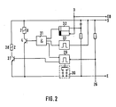
- FIG. 2 shows the line switching device 5 according to FIG. 1 in more detail. It contains in. essentially a flip-flop 32, two monoflops 33 and 29, an AND gate 31, the three inputs of which are connected to the output of the flip-flop 32 and to the negated outputs of the two monoflops 33 and 29, the relay U , 7, with a switching transistor 4 connected in series, the base of which is driven by the output of the AND gate 31, and the relay Z, 28 with a transistor 27, also connected in series, the base of which is driven by the standard output of the second monoflop 29.
- the circuit works as follows. If a connection is to be set up, voltage is applied to the line connection device via the control and power supply line S or the return line E. There the flip-flop 32 is set and the monoflop 33 is triggered. If the connection is busy, a pulse is generated by the speech loop test circuit 2 within 1.5 seconds after S is set, which pulse resets the flip-flop 32 via 3. If, on the other hand, the connection is free, the third input of the AND gate 31 is also set after the mono-flop 33 time has elapsed, as a result of which the switching transistor 4 is turned on by the output of the AND gate 31 and the changeover relay U is excited.
- the relay Z is switched off again and the changeover relay U is switched on accordingly.
- the arrangement according to the invention does not remain limited to a single earth key simulation, but, if the sequence control 10 is set accordingly, two earth key simulations separated by a defined pause can also be carried out for an outside office.
Landscapes
- Engineering & Computer Science (AREA)
- Signal Processing (AREA)
- Computer Networks & Wireless Communication (AREA)
- Telephonic Communication Services (AREA)
- Sub-Exchange Stations And Push- Button Telephones (AREA)
- Road Signs Or Road Markings (AREA)
- Working Measures On Existing Buildindgs (AREA)
- Monitoring And Testing Of Exchanges (AREA)
- Adhesive Tapes (AREA)
- Data Exchanges In Wide-Area Networks (AREA)
- Coupling Device And Connection With Printed Circuit (AREA)
- Communication Control (AREA)
Priority Applications (1)
| Application Number | Priority Date | Filing Date | Title |
|---|---|---|---|
| AT81104055T ATE6894T1 (de) | 1980-07-25 | 1981-05-27 | Schaltungsanordnung zum auf- bzw. abbau einer datenverbindung. |
Applications Claiming Priority (2)
| Application Number | Priority Date | Filing Date | Title |
|---|---|---|---|
| DE19803028236 DE3028236A1 (de) | 1980-07-25 | 1980-07-25 | Schaltungsanordnung zum auf- bzw. abbau einer datenverbindung |
| DE3028236 | 1980-07-25 |
Publications (2)
| Publication Number | Publication Date |
|---|---|
| EP0044918A1 true EP0044918A1 (fr) | 1982-02-03 |
| EP0044918B1 EP0044918B1 (fr) | 1984-03-28 |
Family
ID=6108104
Family Applications (1)
| Application Number | Title | Priority Date | Filing Date |
|---|---|---|---|
| EP81104055A Expired EP0044918B1 (fr) | 1980-07-25 | 1981-05-27 | Circuit pour l'établissement et la libération d'une liaison de données |
Country Status (6)
| Country | Link |
|---|---|
| US (1) | US4434326A (fr) |
| EP (1) | EP0044918B1 (fr) |
| AT (1) | ATE6894T1 (fr) |
| CA (1) | CA1173181A (fr) |
| DE (2) | DE3028236A1 (fr) |
| DK (1) | DK156867C (fr) |
Cited By (1)
| Publication number | Priority date | Publication date | Assignee | Title |
|---|---|---|---|---|
| FR2591835A1 (fr) * | 1985-12-16 | 1987-06-19 | Ricoh Kk | Systeme de transmission de donnees avec limitation dans le temps |
Families Citing this family (8)
| Publication number | Priority date | Publication date | Assignee | Title |
|---|---|---|---|---|
| US4591663A (en) * | 1983-11-17 | 1986-05-27 | Trad, Inc. | Servo-linearized opto-electronic analog interface |
| US4640988A (en) * | 1984-04-03 | 1987-02-03 | Robinton Products, Inc. | Telephone interrupter |
| US4571463A (en) * | 1984-06-01 | 1986-02-18 | Code-A-Phone Corporation | Method and system for automatically inserting at least one pause into means for memorizing a dialing sequence |
| US4654482A (en) * | 1984-10-15 | 1987-03-31 | Deangelis Lawrence J | Home merchandise ordering telecommunications terminal |
| US4698757A (en) * | 1984-11-15 | 1987-10-06 | International Business Machines Corp. | Terminal procedure for utilizing host processor log on and log off prompts |
| JPS62104356A (ja) * | 1985-10-31 | 1987-05-14 | Ricoh Co Ltd | フアクシミリ装置 |
| KR930001641A (ko) * | 1991-06-17 | 1993-01-16 | 정용문 | 키텔레폰 시스템의 리스타트시 통화로 복구 방법 |
| JP3046229B2 (ja) * | 1995-10-04 | 2000-05-29 | キヤノン株式会社 | 電話装置 |
Citations (4)
| Publication number | Priority date | Publication date | Assignee | Title |
|---|---|---|---|---|
| US3959778A (en) * | 1973-09-05 | 1976-05-25 | Compagnie Honeywell Bull (Societe Anonyme) | Apparatus for transferring data from a volatile main memory to a store unit upon the occurrence of an electrical supply failure in a data processing system |
| DE2536200A1 (de) * | 1975-08-13 | 1977-02-24 | Standard Elektrik Lorenz Ag | Schaltungsanordnung zur ueberwachung einer sprechader in fernsprechapparaten |
| DE2814837B1 (de) * | 1978-04-06 | 1979-05-17 | Standard Elek K Lorenz Ag | Datenmodem,insbesondere fuer Bildschirmtextbetrieb |
| EP0023695A1 (fr) * | 1979-08-02 | 1981-02-11 | Siemens Aktiengesellschaft | Circuit de surveillance d'une tension d'entrée |
Family Cites Families (6)
| Publication number | Priority date | Publication date | Assignee | Title |
|---|---|---|---|---|
| DE2719827A1 (de) | 1977-05-04 | 1978-11-09 | Licentia Gmbh | System zur auswahl und wiedergabe von bildschirmtext |
| DE2823283C2 (de) | 1978-05-27 | 1984-02-02 | ANT Nachrichtentechnik GmbH, 7150 Backnang | Verfahren zum Auf- bzw. Abbau einer Verbindung zwischen einem Fernsehgerät und einer Bildschirmtextdatenbank |
| DE2840845C2 (de) | 1978-09-20 | 1985-05-23 | ANT Nachrichtentechnik GmbH, 7150 Backnang | Verfahren zum Auf- bzw. Abbau einer Verbindung zwischen einem Fernsehgerät und einer Bildschirmtextdatenbank |
| DE2931529A1 (de) | 1979-08-03 | 1981-02-19 | Standard Elektrik Lorenz Ag | Teilnehmerseitiges datenuebertragungsgeraet, insbesondere fuer bildschirmtextbetrieb |
| DE2942441C2 (de) | 1979-10-20 | 1986-11-20 | ANT Nachrichtentechnik GmbH, 7150 Backnang | Zusatzeinrichtung zum Auf- bzw. Abbau einer Verbindung zwischen einem Fernsehgerät und einer Bildschirmtextdatenbank |
| US4291200A (en) | 1979-10-31 | 1981-09-22 | Bell Telephone Laboratories, Incorporated | Voice and data switching arrangement |
-
1980
- 1980-07-25 DE DE19803028236 patent/DE3028236A1/de not_active Withdrawn
-
1981
- 1981-05-27 EP EP81104055A patent/EP0044918B1/fr not_active Expired
- 1981-05-27 DE DE8181104055T patent/DE3162861D1/de not_active Expired
- 1981-05-27 AT AT81104055T patent/ATE6894T1/de not_active IP Right Cessation
- 1981-07-10 DK DK307581A patent/DK156867C/da not_active IP Right Cessation
- 1981-07-24 US US06/286,584 patent/US4434326A/en not_active Expired - Fee Related
- 1981-07-24 CA CA000382549A patent/CA1173181A/fr not_active Expired
Patent Citations (4)
| Publication number | Priority date | Publication date | Assignee | Title |
|---|---|---|---|---|
| US3959778A (en) * | 1973-09-05 | 1976-05-25 | Compagnie Honeywell Bull (Societe Anonyme) | Apparatus for transferring data from a volatile main memory to a store unit upon the occurrence of an electrical supply failure in a data processing system |
| DE2536200A1 (de) * | 1975-08-13 | 1977-02-24 | Standard Elektrik Lorenz Ag | Schaltungsanordnung zur ueberwachung einer sprechader in fernsprechapparaten |
| DE2814837B1 (de) * | 1978-04-06 | 1979-05-17 | Standard Elek K Lorenz Ag | Datenmodem,insbesondere fuer Bildschirmtextbetrieb |
| EP0023695A1 (fr) * | 1979-08-02 | 1981-02-11 | Siemens Aktiengesellschaft | Circuit de surveillance d'une tension d'entrée |
Non-Patent Citations (2)
| Title |
|---|
| CONTROL ENGINEERING, Band 25, Nr. 12, Dezember 1978, Seiten 84,85 New York, U.S.A. BEASTON: " Automatically restarting a microprocessor after power failure" * |
| TECHNISCHE MITTEILUNGEN AEG-TELE-FUNKEN, Band 69, Nr. 4, 1979, Seiten 136-140 Berlin, DE. BAMBACH et al.: "Bildschirmtext-Beschreibung des Teilnehmergerätesund der Datenübertragungseinrichtung" * |
Cited By (1)
| Publication number | Priority date | Publication date | Assignee | Title |
|---|---|---|---|---|
| FR2591835A1 (fr) * | 1985-12-16 | 1987-06-19 | Ricoh Kk | Systeme de transmission de donnees avec limitation dans le temps |
Also Published As
| Publication number | Publication date |
|---|---|
| DE3162861D1 (en) | 1984-05-03 |
| CA1173181A (fr) | 1984-08-21 |
| DK156867B (da) | 1989-10-09 |
| DK156867C (da) | 1990-02-26 |
| DK307581A (da) | 1982-01-26 |
| US4434326A (en) | 1984-02-28 |
| ATE6894T1 (de) | 1984-04-15 |
| EP0044918B1 (fr) | 1984-03-28 |
| DE3028236A1 (de) | 1982-03-18 |
Similar Documents
| Publication | Publication Date | Title |
|---|---|---|
| DE69531052T2 (de) | Telekommunikationsverfahren und eine zu seiner Durchführung geeignete Vorrichtung | |
| DE1762969B2 (de) | Schaltungsanordnung zum anzeigen der berechtigungsklasse in fernmeldevermittlungsanlagen | |
| EP0044918B1 (fr) | Circuit pour l'établissement et la libération d'une liaison de données | |
| DE19630456B4 (de) | ISDN-Telefon | |
| DE10253308B4 (de) | Verfahren zur Inbetriebnahme einer Hauskommunikationsanlage sowie mit diesem Verfahren in Betrieb zu nehmende Hauskommunikationsanlage | |
| DE416087C (de) | Schaltungsanordnung fuer Fernsprechanlagen mit Waehlerbetrieb, bei welchen Register von einer anrufenden Stelle eingestellt werden | |
| DE1924096C3 (de) | Schaltungsanordnung zur Herstellung von Verbindungen in einer Fernsprechanlage | |
| DE1292169B (de) | Schaltungsanordnung einer Aussenstelle zur UEbermittlung von binaeren Daten zwischen einer Zentralstelle und einer Mehrzahl dieser in einer Nachrichtenschleife angeordneten Aussenstationen | |
| DE3213217A1 (de) | Verfahren und schaltungsanordnung zur fernbedienung elektrischer geraete | |
| EP0066668B1 (fr) | Procédé pour exploiter une installation téléphonique | |
| DE2740876A1 (de) | Kanalsucher fuer ein funktelefon und verfahren zu deren betrieb | |
| DE878227C (de) | Selbsttaetige Fernsprechanlage, in welcher die Waehlereinstellung von Markierwaehlern gesteuert wird | |
| DE635284C (de) | Anordnung fuer selbsttaetige Fernsprechanlagen | |
| DE2912744C2 (de) | Verfahren für Fernsprech- und Fernsprechnebenstellenanlagen mit zyklischem Abtasten von Verbindungsleitungen unter Zuhilfenahme eines zentral angeordneten Speichers | |
| DE2743623C3 (de) | Elektronisch gesteuertes Fernsprechsystem mit einer elektronische Koppelpunkte aufweisenden Sprechwegedurchschalte- und Tonanschaltekoppelmatrix, sowie mit diesen zugeordneten Haltesätzen | |
| DE1256265C2 (de) | Schaltungsanordnung fuer fernmeldevermittlungsanlagen, insbesondere fernsprechanlagen, mit einem koppelfeld, einrichtungen fuer die aufnahme und weitergabe von wahlkennzeichen und einem zentralen markierer | |
| DE3310608A1 (de) | Schaltungsanordnung fuer eine kleine waehlnebenstellenanlage | |
| DE1512062A1 (de) | Nachrichtenuebertragungssystem | |
| DE3604753A1 (de) | Schaltungsanordnung fuer einen elektronischen rundsteuerempfaenger | |
| DE1512100A1 (de) | Nachrichtenvermittlungsanlage mit Steuersignal-Verzoegerungseinrichtung | |
| DE3325676A1 (de) | Schaltungsanordnung zum anschliessen eines mit einem modem verbundenen datenendgeraetes und einer automatischen waehleinrichtung an eine anschlussleitung einer waehlvermittlungsanlage, insbesondere einer fernsprech-waehlvermittlungsanlage | |
| DE3610730A1 (de) | Einrichtung fuer eine zweit-nebenstellenanlage | |
| DE2748560C2 (de) | Schaltungsanordnung für Fernmeldevermittlungsanlagen, insbesondere Fernsprechvermittlungsanlagen, mit verbindungsindividuellen Schalteinrichtungen und ihnen zugeordneten teilzentralen Steuereinrichtungen | |
| DE965134C (de) | Schaltungsanordnung fuer Zahlengeber zur Einstellung von Waehlern in Fernmelde-, insbesondere Fernsprechanlagen | |
| EP0120459B1 (fr) | Montage pour une petite installation d'abonné avec postes supplémentaires comportant un dispositif de couplage à points de couplage électroniques |
Legal Events
| Date | Code | Title | Description |
|---|---|---|---|
| PUAI | Public reference made under article 153(3) epc to a published international application that has entered the european phase |
Free format text: ORIGINAL CODE: 0009012 |
|
| AK | Designated contracting states |
Designated state(s): AT BE CH DE FR GB LI LU NL SE |
|
| 17P | Request for examination filed |
Effective date: 19820225 |
|
| RAP1 | Party data changed (applicant data changed or rights of an application transferred) |
Owner name: AEG - TELEFUNKEN NACHRICHTENTECHNIK GMBH |
|
| RAP1 | Party data changed (applicant data changed or rights of an application transferred) |
Owner name: ANT NACHRICHTENTECHNIK GMBH |
|
| GRAA | (expected) grant |
Free format text: ORIGINAL CODE: 0009210 |
|
| AK | Designated contracting states |
Designated state(s): AT BE CH DE FR GB LI LU NL SE |
|
| REF | Corresponds to: |
Ref document number: 6894 Country of ref document: AT Date of ref document: 19840415 Kind code of ref document: T |
|
| REF | Corresponds to: |
Ref document number: 3162861 Country of ref document: DE Date of ref document: 19840503 |
|
| ET | Fr: translation filed | ||
| PLBE | No opposition filed within time limit |
Free format text: ORIGINAL CODE: 0009261 |
|
| STAA | Information on the status of an ep patent application or granted ep patent |
Free format text: STATUS: NO OPPOSITION FILED WITHIN TIME LIMIT |
|
| 26N | No opposition filed | ||
| R20 | Corrections of a patent specification |
Effective date: 19880406 |
|
| PGFP | Annual fee paid to national office [announced via postgrant information from national office to epo] |
Ref country code: GB Payment date: 19930511 Year of fee payment: 13 |
|
| PGFP | Annual fee paid to national office [announced via postgrant information from national office to epo] |
Ref country code: FR Payment date: 19930518 Year of fee payment: 13 |
|
| PGFP | Annual fee paid to national office [announced via postgrant information from national office to epo] |
Ref country code: SE Payment date: 19930527 Year of fee payment: 13 Ref country code: AT Payment date: 19930527 Year of fee payment: 13 |
|
| PGFP | Annual fee paid to national office [announced via postgrant information from national office to epo] |
Ref country code: NL Payment date: 19930531 Year of fee payment: 13 |
|
| PGFP | Annual fee paid to national office [announced via postgrant information from national office to epo] |
Ref country code: BE Payment date: 19930601 Year of fee payment: 13 |
|
| PGFP | Annual fee paid to national office [announced via postgrant information from national office to epo] |
Ref country code: LU Payment date: 19930602 Year of fee payment: 13 |
|
| PGFP | Annual fee paid to national office [announced via postgrant information from national office to epo] |
Ref country code: CH Payment date: 19930617 Year of fee payment: 13 |
|
| EPTA | Lu: last paid annual fee | ||
| PG25 | Lapsed in a contracting state [announced via postgrant information from national office to epo] |
Ref country code: LU Free format text: LAPSE BECAUSE OF NON-PAYMENT OF DUE FEES Effective date: 19940527 Ref country code: GB Effective date: 19940527 Ref country code: AT Effective date: 19940527 |
|
| PG25 | Lapsed in a contracting state [announced via postgrant information from national office to epo] |
Ref country code: SE Effective date: 19940528 |
|
| PG25 | Lapsed in a contracting state [announced via postgrant information from national office to epo] |
Ref country code: LI Effective date: 19940531 Ref country code: CH Effective date: 19940531 Ref country code: BE Effective date: 19940531 |
|
| PGFP | Annual fee paid to national office [announced via postgrant information from national office to epo] |
Ref country code: DE Payment date: 19940707 Year of fee payment: 14 |
|
| BERE | Be: lapsed |
Owner name: ANT NACHRICHTENTECHNIK G.M.B.H. Effective date: 19940531 |
|
| PG25 | Lapsed in a contracting state [announced via postgrant information from national office to epo] |
Ref country code: NL Effective date: 19941201 |
|
| NLV4 | Nl: lapsed or anulled due to non-payment of the annual fee | ||
| GBPC | Gb: european patent ceased through non-payment of renewal fee |
Effective date: 19940527 |
|
| EUG | Se: european patent has lapsed |
Ref document number: 81104055.9 Effective date: 19941210 |
|
| PG25 | Lapsed in a contracting state [announced via postgrant information from national office to epo] |
Ref country code: FR Effective date: 19950131 |
|
| REG | Reference to a national code |
Ref country code: CH Ref legal event code: PL |
|
| EUG | Se: european patent has lapsed |
Ref document number: 81104055.9 |
|
| REG | Reference to a national code |
Ref country code: FR Ref legal event code: ST |
|
| PG25 | Lapsed in a contracting state [announced via postgrant information from national office to epo] |
Ref country code: DE Effective date: 19960201 |