EP0045014B1 - Anlage zum Härten von mit Harz versehenen Bändern mittels Elektronen - Google Patents
Anlage zum Härten von mit Harz versehenen Bändern mittels Elektronen Download PDFInfo
- Publication number
- EP0045014B1 EP0045014B1 EP81105605A EP81105605A EP0045014B1 EP 0045014 B1 EP0045014 B1 EP 0045014B1 EP 81105605 A EP81105605 A EP 81105605A EP 81105605 A EP81105605 A EP 81105605A EP 0045014 B1 EP0045014 B1 EP 0045014B1
- Authority
- EP
- European Patent Office
- Prior art keywords
- web
- radiation
- chamber
- radiation resistant
- target area
- Prior art date
- Legal status (The legal status is an assumption and is not a legal conclusion. Google has not performed a legal analysis and makes no representation as to the accuracy of the status listed.)
- Expired
Links
Images


Classifications
-
- B—PERFORMING OPERATIONS; TRANSPORTING
- B24—GRINDING; POLISHING
- B24D—TOOLS FOR GRINDING, BUFFING OR SHARPENING
- B24D11/00—Constructional features of flexible abrasive materials; Special features in the manufacture of such materials
- B24D11/001—Manufacture of flexible abrasive materials
- B24D11/005—Making abrasive webs
-
- G—PHYSICS
- G21—NUCLEAR PHYSICS; NUCLEAR ENGINEERING
- G21K—HANDLING OF PARTICLES OR IONISING RADIATION NOT OTHERWISE PROVIDED FOR; IRRADIATION DEVICES; GAMMA RAY OR X-RAY MICROSCOPES
- G21K5/00—Irradiation devices
- G21K5/10—Irradiation devices with provision for relative movement of beam source and object to be irradiated
Definitions
- the invention relates to an apparatus for electron irradiation of a resin coating applied onto a web material
- a source of high energy electron radiation being disposed inside a radiation resistant chamber having openings for said web entering and exiting said chamber, first means externally of the chamber for guiding said web along a pathway from said entrance opening into a target area of said electron radiation source and further receiving said web from said target area at the exit opening, said web being guided such that its coated side is maintained out of contact with any object during its movement at least to a position where it leaves said target area.
- binders are for example glutelin glue, phenolic resins and, if waterproof papers are desired, polyurethane resins, epoxy resins and alkyd resins, possibly in combination with melamine resins. Special requirements as related to technique, apparatus and time are necessary for the curing process. To avoid destruction of the substrates usually consisting of polyester or cellulose, curing should be effected at a maximum temperature of 120° to 130°C.
- the drying of the coated material sufficient to be rolled for curing generally requires several hours, and is therefore carried out in a festoon oven.
- the festoon oven through which the coated web material is passing enable a long drying or partial cure process, but there are also disadvantages, such as the formation of defects where the material is suspended, sagging of the binder and changing of the grain position due to the vertical suspension, variation of temperature and the resulting inconsistent crosslinking of the binder produced by the necessary slow air circulation.
- After removal from the festoon oven it is then necessary to completely cure the rolls of partially cured abrasives by slowly heating in an auxiliary oven. Slow heating is necessary to prevent an uneven cure caused by widely different temperatures between the outside and inside of the rolls.
- abrasives by coating a substrate using a photopolymerizable curable synthetic resin as well as abrasive grains and by subsequently curing the applied layer by means of infrared radiation.
- the relatively long curing period of the synthetic resin is a disadvantage of this processing method. Owing to the long curing period and the elevated temperature the substrate is also strongly attacked. Furthermore the processing speed is low during the production of abrasives.
- the major areas of production may be considered as first the cloth treatment to prepare resin treated base cloth for application of abrasives and second the making of the coated abrasives using the previously prepared base cloth.
- the base cloth is coated with at least one backing coat of resin which impregnates the cloth with resin and fills interstices in the back of the cloth.
- the backing cloth is also coated with at least one face coat that fills interstices of the cloth on the side where abrasive grain is placed.
- the face coat(s) of the backing cloth also aids in adhesion of the coats containing the grains onto the cloth.
- the second major area of coated abrasive formation is the drying or partial curing of the make coat which contains the grain and drying or partial cure of the size coat which is an overcoat placed onto the coated abrasive after the grain is at least partially cured and adhered onto the backing of the make coat.
- the partial curing of the make and size coats as set forth generally is done in a lengthy festoon dryer that requires a tremendous amount of floor space and energy. Further, both the festoon and auxiliary ovens where the curing takes place over a long period are difficult to completely control for accurate temperature. There also is the problem of the resin and grain shifting positions during curing because of the long hang times in the partially cured or uncured form. Then after removal from the festoon oven, further energy is used in the oven treatment of the rolls to obtain complete cure.
- coated abrasives When forming coated abrasives, there may be required very thick coats of resins compared with prior uses of the electron beam. The resins necessary also are very sticky prior to being completely cured. Therefore, multiple path systems such as disclosed in some prior electron beam curing systems such as US-A-3 022 543 are not satisfactory since if the resins touch a roller the system will gum-up and not perform.
- Another difficulty with the formation of abrasives with electron beam curing apparatus such as presently available is that in coated abrasive formation there is always a certain amount of abrasive grain which becomes detached from the coated abrasive during formation and can detrimentally affect the equipment if it is not possible to regularly clean and maintain the equipment.
- the equipment becomes contaminated by adhesive buildup and by material such as abrasive grit and dirt which becomes embedded in the abrasive.
- Another difficulty is that generally coated abrasives are made with multiple changes of grit size, backings and resins coatings. Therefore it is necessary to stop and start the system at relatively frequent intervals.
- the apparatus indicated at the very beginning is known from FR-A-2 101 682.
- This apparatus comprises a radiation resistant chamber in which a source of high energy electrons is installed. A web passes across this chamber adjacent to the electron source. Since guiding means for guiding the web are positioned outside the chamber it follows as a consequence that the free part of the web inside the chamber is only allowed to be relatively short because otherwise it may happen that the resin coated surface of the web touches the respective walls at the entrance and exit openings. Consequently, this chamber is not accessible by a person. Since this reference does not mention how the interior of this chamber may be accessed, it has to be assumed that several of the shielding concrete blocks have to be moved to gain access to the interior. No shielding is provided for the electron source having the consequence that the walls limiting the chamber have to be very thick and, therefore, quite heavy.
- the problem to be solved by the invention is to improve an apparatus as defined at the very beginning of this specification such that it may be easily threaded with web materials and quickly serviced.
- the apparatus according to the invention is extremely useful for electron irradiation of a resin coating applied onto a web material.
- the apparatus according to the invention allows easy access to the equipment and provides, therefore, the possibility of quickly cleaning and servicing the relative parts and devices of the apparatus. Furthermore, the apparatus may be easily threaded with webs.
- the apparatus according to the invention is extremely useful for the formation of abrasives. During the production of such a material there is always a certain amount of abrasive grains which become detached from the coated abrasive during formation and can effect the equipment detrimentally. The easy access allows quick cleaning of the apparatus resulting in only a small loss in "up" time.
- said second means for carrying said web comprises alternative carrying means allowing said web to be moved through said target area such that the side of said web bearing said resin coating faces away from or towards said source of high energy electron radiation when passing through said target area.
- Another advantageous embodiment is characterised in that said web may be carried into and through its normal path in said radiation resistant chamber while said source of high energy electron radiation is in inoperative condition and while a person in said radiation resistant chamber makes adjustment to the second means for carrying the web in said radiation resistant chamber.
- This embodiment allows adjusting and viewing of the web as it moves through the apparatus prior to activation of the electron beam.
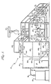
- FIG. 1 illustrates the set-up of one embodiment of the apparatus 10 of the invention illustrating the alternative pathways for the alternative uses of the apparatus.
- the apparatus 10 is composed of an unwinder 22, printer 12', coater 14, electrostatic grain applicator 16 and electron beam chamber 20. Also illustrated is the high voltage power supply 21 and winder roll 18.
- the unwinder 22 holds supply roll 23 into which may be placed a blank cloth to be treated with a backing coat, face coat or the resin treated cloth which will be treated with a make coat prior to putting grain on the cloth or a roll of abrasive which has grain on it but which is placed into the unwinder 22 for treatment with a size coat over the grain.
- the printer 12' utilizes a roll 26 to print the necessary descriptive material on the back of the cloth or paper backing.
- Such information as the grit size, recommended use of the coated abrasive and trademarks are printed on the backing.
- the print roll 26 runs against impression roll 27.
- Element 24 is a beta gauge device for measuring the weight of the web leaving roll 23.
- the coating device 14 is known in the art as is the printer 12'.
- the coating device 14 may utilize a doctor-blade coater 32 to push a resin onto the web 13 or may use a transfer rubber roll 36 in sump 37 to apply resin to the web being passed through the apparatus. Rollls 34 and 36 are utilized to carefully control the web during coating.
- Beta gauge measuring device 40 measures the weight of the coating to insure the ability to control for accurate coating. Coating thickness of about 0,51 mm may be applied in coated abrasive formation.
- Pressure supply 43 adjusts the coating roll pressure on the web during coating to control resin weight.
- the electrostatic coater comprises a system whereby abrasive grain is applied to a vibrating lower plate 42.
- a vibrating belt and grid could be used rather than plate.
- the web 13 passes against grounded plate 44 leaving a gap between the web 13 held against plate 44 and the lower electrostatically charged plate 42.
- the abrasive grains are attracted by the electrostatic charge and embed themselves in the wet resin on the web 13. By this method the points of the grains are- oriented upward away from the web surface for best cutting.
- a source of abrasive grain 46 is applied to lower plate 42 by the vibratory feeder 48. The rate of application is controlled by means not shown to provide a continuous moving layer of particles of vibratory feeder plate 42. Other electrostatic feeder arrangements may be utilized if desired.
- the web 13 enters the equipment vault 20 at 52 and if radiated by the electron beam from the wet face side exits at 54 or if subjected to the electron beam from the backside exits at 56.
- the tracking within the equipment vault 20 will be described in more detail below.
- the winder roll 64 driven by means 62 not shown in detail gathers and rolls the treated web 13 onto a roll which may be moved by overhead hoist 66. The roll if it is to be further treated is then moved down to the location of the supply roll 22 or a finished product may be stored or moved to final shipping or cutting.
- the stair and railing 68 provides access to the upper portion of the radiation equipment vault and to the winder roll.
- Guard 70 counter-balanced by weight 72 provides shielding for the exit 56.
- Access door 74 provides entry for people into the radiation equipment vault for maintenance and threading of the web through the conveyor rollers and the inerting chamber.
- the beta gauge 65 allows measuring the weight of the total weight of make coat.
- the equipment vault walls are generally of 3-inch thick steel with lead lining in critical areas as will be set forth in more detail below.
- Figures 2 and 3 illustrate the equipment vault housing the electron beam unit with special emphasis as to the shielding and service features of the equipment vault and electron beam curing apparatus system of the instant invention.
- Figure 2 is a section along line 2-2 of Figure 1 taken just above the electron beam curing unit.
- Figure 3 is a view taken along line 3-3 of Figure 2 that illustrates the mounting of the electron beam gun, shielding within the equipment vault for the electron beam unit and the multiple pathways for the web which allow curing from either face of the web.
- the radiation equipment vault generally indicated as 12 is formed of a front wall 92, back wall 96 and side walls 94 and 98. There is a door 74 in the side 98.
- Entrance through door 74 is into area 99 which constitutes an entrance-way and also is shielded by partition 118, commonly referred to as a maze.
- Partition 118 and all four sides of the equipment vault 12 as shown are formed of 7,6 cm thick steel. The steel is covered with lead at points of increased need for radiation control.
- the service area around the electron beam gun 108 is identified as areas 101 and 103. It is noted that areas 101 and 103 are joined above the chamber which houses the electron beam generating unit. From area 101 the target chamber 105 is entered by door 88 up stairs 84. Target chamber 105 has a floor which is at easy working level for servicing the inerting chamber 82.
- the target area steel wall is covered with about 7,6 cm of lead to provide further protection from radiation in the surrounding areas.
- Access to area 103 is up stairs 86 through door 90. It is noted that the entire enclosure of the vault is a generally square floor area. Area 103 has easy access to service the electron beam generating unit and also to aid in stringing of the webbing to be cured by the unit 108. Step 114 aids in reaching the upper portion of the chamber for web manipulation.
- the area around the apparatus during operation is at a radiation level below 0,25 millirems per hour so as to be safe without the need for radiation badging of employees in the area, the walls 92, 94, 96, 98 of the radiation resistant chamber 12 being sufficiently thick for this.
- the electron beam generating unit 108 is entirely ehclosed within the container of which the sides 106 and 104 are illustrated in Figure 2 and the upper and lower portions 107 and 109 are illustrated in Figure 3.
- This inner chamber is formed of about 2,5 cm steel panels with additional radiation absorbing material comprising about 3,8 cm of lead on all four sides of about the third of the chamber towards the inerting box, about 2,5 cm of addition lead on the middle third of the chamber and about 1,3 cm additional lead on the rear portion of the chamber.
- the electron beam generating unit may be adjusted and moved for service along suspending steel rods 112. Tubes 120 and 122 bring cooling gases into the equipment cavity for cooling of the electron beam window.
- Inerting gas as is known, is necessary for the effective electron beam curing of resins as oxygen interferes with the curing.
- the inerting gas normally nitrogen, enter the inerting chamber 82 from storage tanks (not shown) outside the chamber by pipes (not shown).
- the ceiling 132 of the equipment vault 12 contains additional lead shielding material.
- the ceiling has 6,4 cm of lead over the 2,5 cm steel plate ceiling at the portion directly above the inerting chamber. Extending on each side of the 6,4 cm thick portion are 2,5 thicknesses of lead 136 and 138. Then further lead of about 1,3 cm thickness extends to the edge of the roof 132.
- additional lead shielding 180 and 188 of 2,5 cm thickness on the shield 182 and 184 for which also carry rollers 160 and 154, respectively.
- the shields 182 and 184 themselves are of 2,5 cm steel.
- the equipment vault sits on the ground floor and therefore does not need additional radiation absorbing materials on the bottom portion.
- a surface with a radiation measuring device is carried out for any areas of higher radiation than .25 millirems per hour. Then, additional shielding is added to any areas of higher radiation.
- the enclosure may be large enough that the entrances and exists for the webs are more than the about 2,4 m required to dissipate the electron type radiation given off.
- the x-rays given off are the type of rays requiring the most shielding as they do not dissipate quickly with distance.
- the need for shielding has prevented previous web devices from being suitable for cloth finishing where thick coats of resin were placed on the cloth, or where cleaning of contamination needs to be carried out frequently.
- the up time of the equipment is rapidly reduced if contamination can not be easily, quickly and rapidly removed.
- the possibility of allowing cleaning, service and web stringing by a person who is entirely within the radiation chamber is an advantage of the instant invention.
- the large chamber with 2,4 to 3,0 m from the electron beam source to the web exits and web entrances is another advantage.
- the large entrance and exits holes for the web from the vault also are believed novel in the art.
- the holes for the web are about 5,8 cm up to about 10 cm in height. Holes of about 10 cm are preferred for ease of stringing the web.
- the large entrance holes ease the task of stringing the web and also minimize the chance of contact by the web surface which would harm the product.
- the holes may be angled where passing through the wall to aid radiation control.
- the arrangement of conveyor rollers within the apparatus of the invention that allows adjustment such that the electron beam may impinge on either the resin wet face or the back surface of a web passing through the device will now be explained with reference to Figures 4 and 5.
- the web enters at 52 after passing under roll 142.
- the wet resin side here faces downward.
- roller 144 controls movement of the resin treated material for its movement to roller 146.
- the web material passes to roller 148, upward to roller 150 and then downward past out of contact roller 156 and through the inerting chamber 82 where electron beam curing takes place.
- the cured web Exiting from the inerting chamber the cured web is now contacted on the cured resin side by roller 152, it then passes to conveyor rollers 154 and 157 prior to exiting through opening 54 over roller 143.
- the cured web then is led by appropriate rollers or other guide means to winder 64.
- the instance of a web to be cured by exposure to the electron beam from the side opposite to where the wet resin coat is located is illustrated by Figure 4.
- the track followed within the chamber would be entry through aperture 52 followed by passing over rollers 144 and 146 then to roller guide 152 for passage directly upward through inerting chamber 82 and over roller 156 prior to exiting by passing over rollers 160 and 162 as the web passes through aperture 56.
- the web then moves to take up roller 64 passing through beta gauge 85 and over roller 163.
- the sealing device 166 where power cable 76 enters the vault is packed with lead packing material to minimize radiation.
- the radiation chamber is protected with interlock devices that do not allow activation of the electron beam until all doors are closed and all guards and covers are in place.
- the chamber also has internal alarms and shut offs to prevent injury by trapping a person inside the vault.
- the side of the inner box or chamber that houses the electron beam unit is formed with three bolted panels on sides 104. and 106. Removal of the panels permits easy access for servicing and adjustment of the electron beam unit.
- the side panels are of 2,5 cm steel with additional thicknesses of lead towards the end of the gun adjacent the inerting chamber.
- the service area below the chamber for the gun is also accessed by hinged or sliding steel panels 119 for threading of the web through the device of the invention.
- the source of high energy electrons 108 may be any commercial available electron beam unit capable of generating energy of about 175,000 to about 1,000,000 volts.
- the unit may be either a curtain or scanning electron beam. In one instance it was successfully found that a scanning electron beam unit of a capacity of 500 kw was suitable. A unit of about 300 kw to about 500 kw is suitable for the instant coatings and speeds of up to about 122 m per minute.
- the source of high energy radiation could be a nuclear source, but it is not preferred since nuclear control is much more difficult than the electron beam.
- Any suitable resins may be utilized for the backing and make coat layers of the invention.
- the length of cure and amount of radiation needed for cure are a variable depending on the speed of the web, amount of resin and purity of inserting gas in the inerting chamber 82. It is anticipated that web speeds of up to about 122 m per minute are feasible for electron beam curing.
- the thickness of the radiation protection material may be varied depending on the strength of the electron beam gun utilized in the chamber.
- the simplified access and stringing abilities of the chamber could be utilized without the possibility of multiple ways of exposing the material.
- the radiation vault could be only used for coated abrasive formation rather than also being used for cloth finishing.
- a series of radiation vaults each treating a specific layer i.e., size coat, make coat, face coat, back coat
- the apparatus of the invention could be utilized to produce materials other than coated abrasives such as plastic coated fabrics or floor coverings.
- the apparatus of the invention is particularly suitable for any use wherein an electron beam curable resin is coated onto a floppy backing material of cloth, paper or foil and where the thickness of the coating or added particles on the coating create the likelihood that the machine will require constant adjustment and frequent cleaning and access for threading or repairing broken webs.
- the vault could be formed with more compartments or other radiation absorbing materials, such as cement or the use of more lead lining and thinner steel.
- the web could be partly carried by conveyors or edge grippers rather than rollers. The paths of webs could be varied depending on location of the coating applicator and the electrostatic grain coats for applying abrasive grains.
- the apparatus according to the invention is also suited to treat thick resin coating on web backings for other purposes, such as floor covers, wallpaper and artificial leather.
Landscapes
- Engineering & Computer Science (AREA)
- Manufacturing & Machinery (AREA)
- Mechanical Engineering (AREA)
- Physics & Mathematics (AREA)
- General Engineering & Computer Science (AREA)
- High Energy & Nuclear Physics (AREA)
- Application Of Or Painting With Fluid Materials (AREA)
- Coating Apparatus (AREA)
- Laminated Bodies (AREA)
- Chemical Or Physical Treatment Of Fibers (AREA)
- Paper (AREA)
Claims (9)
Applications Claiming Priority (2)
| Application Number | Priority Date | Filing Date | Title |
|---|---|---|---|
| US06/172,722 US4345545A (en) | 1980-07-28 | 1980-07-28 | Apparatus for electron curing of resin coated webs |
| US172722 | 2002-06-14 |
Publications (2)
| Publication Number | Publication Date |
|---|---|
| EP0045014A1 EP0045014A1 (de) | 1982-02-03 |
| EP0045014B1 true EP0045014B1 (de) | 1985-05-29 |
Family
ID=22628926
Family Applications (1)
| Application Number | Title | Priority Date | Filing Date |
|---|---|---|---|
| EP81105605A Expired EP0045014B1 (de) | 1980-07-28 | 1981-07-16 | Anlage zum Härten von mit Harz versehenen Bändern mittels Elektronen |
Country Status (5)
| Country | Link |
|---|---|
| US (1) | US4345545A (de) |
| EP (1) | EP0045014B1 (de) |
| JP (1) | JPS5766959A (de) |
| CA (1) | CA1171383A (de) |
| DE (1) | DE3170706D1 (de) |
Families Citing this family (13)
| Publication number | Priority date | Publication date | Assignee | Title |
|---|---|---|---|---|
| US4410560A (en) * | 1981-10-09 | 1983-10-18 | Album Graphics, Inc. | Continuous web printing apparatus, process and product thereof |
| US4652274A (en) * | 1985-08-07 | 1987-03-24 | Minnesota Mining And Manufacturing Company | Coated abrasive product having radiation curable binder |
| US4927431A (en) * | 1988-09-08 | 1990-05-22 | Minnesota Mining And Manufacturing Company | Binder for coated abrasives |
| CA2058700C (en) * | 1991-01-08 | 2000-04-04 | David E. Williams | Polymer backed material with non-slip surface |
| US5435816A (en) * | 1993-01-14 | 1995-07-25 | Minnesota Mining And Manufacturing Company | Method of making an abrasive article |
| US5433979A (en) * | 1993-05-17 | 1995-07-18 | Norton Company | Method of producing a non-slip sheet |
| US5514028A (en) * | 1994-01-07 | 1996-05-07 | Ali; Christopher A. | Single sheet sandpaper delivery system and sandpaper sheet therefor |
| DE19882252T1 (de) | 1997-03-26 | 2000-05-18 | Electron Processing Systems In | Technik zur Innensterilisation eines Behälters mit offener Öffnung mittels Elektronen |
| US6127687A (en) * | 1998-06-23 | 2000-10-03 | Titan Corp | Article irradiation system having intermediate wall of radiation shielding material within loop of conveyor system that transports the articles |
| US6698412B2 (en) | 2001-01-08 | 2004-03-02 | Catalytica Energy Systems, Inc. | Catalyst placement in combustion cylinder for reduction on NOx and particulate soot |
| JP2006114884A (ja) * | 2004-09-17 | 2006-04-27 | Ebara Corp | 基板洗浄処理装置及び基板処理ユニット |
| JP5207444B2 (ja) * | 2007-11-22 | 2013-06-12 | 日本ミクロコーティング株式会社 | 研磨シート及び研磨シートの製造方法 |
| JP5209284B2 (ja) * | 2007-11-28 | 2013-06-12 | 日本ミクロコーティング株式会社 | 研磨シートおよび研磨シートの製造方法 |
Family Cites Families (20)
| Publication number | Priority date | Publication date | Assignee | Title |
|---|---|---|---|---|
| US2741704A (en) * | 1953-06-22 | 1956-04-10 | High Voltage Engineering Corp | Irradiation method and apparatus |
| US2956904A (en) * | 1954-11-04 | 1960-10-18 | Minnesota Mining & Mfg | Pressure-sensitive adhesive tapes |
| BE544324A (de) * | 1955-01-11 | |||
| US3022543A (en) * | 1958-02-07 | 1962-02-27 | Grace W R & Co | Method of producing film having improved shrink energy |
| US3081485A (en) * | 1958-11-20 | 1963-03-19 | Steigerwald Karl Heinz | Process and apparatus for treating synthetic plastic materials |
| US3418155A (en) | 1965-09-30 | 1968-12-24 | Ford Motor Co | Electron discharge control |
| GB1168641A (en) | 1966-05-19 | 1969-10-29 | British Iron Steel Research | Formation of Polymer Coatings on Substrates. |
| US3433947A (en) * | 1966-06-02 | 1969-03-18 | High Voltage Engineering Corp | Electron beam accelerator with shielding means and electron beam interlocked |
| US3564238A (en) * | 1967-05-08 | 1971-02-16 | Deering Milliken Res Corp | Irradiation apparatus in combination web handling means |
| US3628987A (en) * | 1967-07-12 | 1971-12-21 | Sekisui Chemical Co Ltd | Pressure sensitive adhesive film |
| US3676249A (en) * | 1967-12-18 | 1972-07-11 | Jerome H Lemelson | Irradiation method for production of fiber-reinforced polymeric composites |
| SE356469B (de) * | 1969-06-13 | 1973-05-28 | Conservatome | |
| CA893392A (en) * | 1970-02-06 | 1972-02-15 | R. Green William | Irradiation apparatus |
| GB1353831A (en) * | 1970-07-15 | 1974-05-22 | Armco Steel Corp | Apparatus and process for radiation curing of coated strip-like material |
| US4047903A (en) * | 1972-09-26 | 1977-09-13 | Hoechst Aktiengesellschaft | Process for the production of abrasives |
| US3925671A (en) * | 1972-11-07 | 1975-12-09 | Bell Telephone Labor Inc | Irradiating strand material |
| GB1509069A (en) | 1974-06-17 | 1978-04-26 | Chitouras C | Method of curing particle-coated substrates |
| CA1055421A (en) | 1974-12-09 | 1979-05-29 | Samuel V. Nablo | Process and apparatus for the curing of coatings on sensitive substrates by electron irradiation |
| DE2501381C2 (de) | 1975-01-15 | 1982-06-24 | Karl-Heinz 6233 Kelkheim Tetzlaff | Verfahren zur Bestrahlung von Gegenständen oder Gütern in einer Gamma-Bestrahlungsanlage |
| US4252413A (en) | 1978-10-05 | 1981-02-24 | Energy Sciences Inc. | Method of and apparatus for shielding inert-zone electron irradiation of moving web materials |
-
1980
- 1980-07-28 US US06/172,722 patent/US4345545A/en not_active Expired - Lifetime
-
1981
- 1981-07-16 DE DE8181105605T patent/DE3170706D1/de not_active Expired
- 1981-07-16 EP EP81105605A patent/EP0045014B1/de not_active Expired
- 1981-07-23 CA CA000382414A patent/CA1171383A/en not_active Expired
- 1981-07-27 JP JP56116517A patent/JPS5766959A/ja active Pending
Also Published As
| Publication number | Publication date |
|---|---|
| US4345545A (en) | 1982-08-24 |
| EP0045014A1 (de) | 1982-02-03 |
| JPS5766959A (en) | 1982-04-23 |
| DE3170706D1 (en) | 1985-07-04 |
| CA1171383A (en) | 1984-07-24 |
Similar Documents
| Publication | Publication Date | Title |
|---|---|---|
| GB2087263A (en) | Resin systems for high energy electron curable resin coated webs | |
| EP0045014B1 (de) | Anlage zum Härten von mit Harz versehenen Bändern mittels Elektronen | |
| CA1256397A (en) | Method and apparatus for electron curing on a cooled drum | |
| US4246297A (en) | Process and apparatus for the curing of coatings on sensitive substrates by electron irradiation | |
| US3741155A (en) | Apparatus for particulate coating of an elongate article | |
| US4385239A (en) | Inerting chamber for electron curing of resin coated webs | |
| US20020033134A1 (en) | Method and apparatus for processing coatings, radiation curable coatings on wood, wood composite and other various substrates | |
| US4308296A (en) | Method of curing particle-coated substrates | |
| US5178679A (en) | Paint spray booth with longitudinal air flow | |
| EP0236616B1 (de) | Verfahren und Vorrichtung zum Härten von beschichteten porösen und anderen Bahnstrukturen mit Elektronenstrahl | |
| US4020354A (en) | Treatment of tire making components | |
| EP1725341A2 (de) | Strahlungsgerät sowie pulverauftragsstation und anordnung zur beschichtung von temperatursensiblen materialien und zugehöriges verfahren | |
| KR20140105843A (ko) | 기판을 처리하기 위한 시스템 및 방법들 | |
| EP0023754B1 (de) | Apparat und Verfahren zur elektrostatischen Aufzeichnung | |
| RU2743076C1 (ru) | Способ и устройство нанесения покрытия на одну и/или обе стороны металлической подложки в форме полосы | |
| IL62179A (en) | Method and apparatus for fabricating and surface treating of an abrasion resistant sheet from crystallizable polypropylene | |
| JPS6037151B2 (ja) | 粒子被覆基板を硬化する方法 | |
| EP0427753A1 (de) | Beschichtungsapparat mit abdeckvorrichtung. | |
| UA129378C2 (uk) | Спосіб виготовлення декоративної панелі, що включає нанесення плівки на підкладку методом електростатичного заряджання | |
| US3745846A (en) | Conveyor belt construction | |
| US6517909B1 (en) | Method for using a patterned backing roller for curtain coating a liquid composition to a web | |
| US6313444B1 (en) | Radiant oven | |
| CA1065795A (en) | Treatment of tire making components | |
| US6242051B1 (en) | Coating method using electrostatic assist | |
| US3565662A (en) | Strip coating method and apparatus |
Legal Events
| Date | Code | Title | Description |
|---|---|---|---|
| PUAI | Public reference made under article 153(3) epc to a published international application that has entered the european phase |
Free format text: ORIGINAL CODE: 0009012 |
|
| AK | Designated contracting states |
Designated state(s): DE FR GB |
|
| 17P | Request for examination filed |
Effective date: 19820802 |
|
| RAP1 | Party data changed (applicant data changed or rights of an application transferred) |
Owner name: KENNECOTT CORPORATION |
|
| GRAA | (expected) grant |
Free format text: ORIGINAL CODE: 0009210 |
|
| AK | Designated contracting states |
Designated state(s): DE FR GB |
|
| REF | Corresponds to: |
Ref document number: 3170706 Country of ref document: DE Date of ref document: 19850704 |
|
| ET | Fr: translation filed | ||
| PLBE | No opposition filed within time limit |
Free format text: ORIGINAL CODE: 0009261 |
|
| STAA | Information on the status of an ep patent application or granted ep patent |
Free format text: STATUS: NO OPPOSITION FILED WITHIN TIME LIMIT |
|
| 26N | No opposition filed | ||
| PG25 | Lapsed in a contracting state [announced via postgrant information from national office to epo] |
Ref country code: FR Free format text: LAPSE BECAUSE OF NON-PAYMENT OF DUE FEES Effective date: 19880331 |
|
| PG25 | Lapsed in a contracting state [announced via postgrant information from national office to epo] |
Ref country code: DE Effective date: 19880401 |
|
| GBPC | Gb: european patent ceased through non-payment of renewal fee | ||
| REG | Reference to a national code |
Ref country code: FR Ref legal event code: ST |
|
| PG25 | Lapsed in a contracting state [announced via postgrant information from national office to epo] |
Ref country code: GB Free format text: LAPSE BECAUSE OF NON-PAYMENT OF DUE FEES Effective date: 19881118 |