EP0045038A1 - Ensemble de fixation de l'extrémité d'un câble électrique à conducteur extérieur à ondulations droites dans le corps d'un connecteur - Google Patents
Ensemble de fixation de l'extrémité d'un câble électrique à conducteur extérieur à ondulations droites dans le corps d'un connecteur Download PDFInfo
- Publication number
- EP0045038A1 EP0045038A1 EP81105714A EP81105714A EP0045038A1 EP 0045038 A1 EP0045038 A1 EP 0045038A1 EP 81105714 A EP81105714 A EP 81105714A EP 81105714 A EP81105714 A EP 81105714A EP 0045038 A1 EP0045038 A1 EP 0045038A1
- Authority
- EP
- European Patent Office
- Prior art keywords
- connector
- outer conductor
- fixing device
- sleeve
- ring
- Prior art date
- Legal status (The legal status is an assumption and is not a legal conclusion. Google has not performed a legal analysis and makes no representation as to the accuracy of the status listed.)
- Granted
Links
- 239000004020 conductor Substances 0.000 title claims abstract description 28
- 229920001971 elastomer Polymers 0.000 claims description 7
- 239000002184 metal Substances 0.000 claims description 6
- 239000000806 elastomer Substances 0.000 claims description 4
- 238000004873 anchoring Methods 0.000 claims description 2
- 230000007704 transition Effects 0.000 abstract 2
- 208000031968 Cadaver Diseases 0.000 description 2
- 241001080024 Telles Species 0.000 description 1
- 238000004026 adhesive bonding Methods 0.000 description 1
- 230000000694 effects Effects 0.000 description 1
- 238000003754 machining Methods 0.000 description 1
- 239000000463 material Substances 0.000 description 1
- 238000000034 method Methods 0.000 description 1
- 238000003801 milling Methods 0.000 description 1
- 230000002093 peripheral effect Effects 0.000 description 1
- 239000004033 plastic Substances 0.000 description 1
- -1 polytetrafluoroethylene Polymers 0.000 description 1
- 229920001343 polytetrafluoroethylene Polymers 0.000 description 1
- 239000004810 polytetrafluoroethylene Substances 0.000 description 1
- 230000001681 protective effect Effects 0.000 description 1
Images
Classifications
-
- H—ELECTRICITY
- H01—ELECTRIC ELEMENTS
- H01R—ELECTRICALLY-CONDUCTIVE CONNECTIONS; STRUCTURAL ASSOCIATIONS OF A PLURALITY OF MUTUALLY-INSULATED ELECTRICAL CONNECTING ELEMENTS; COUPLING DEVICES; CURRENT COLLECTORS
- H01R24/00—Two-part coupling devices, or either of their cooperating parts, characterised by their overall structure
- H01R24/38—Two-part coupling devices, or either of their cooperating parts, characterised by their overall structure having concentrically or coaxially arranged contacts
- H01R24/40—Two-part coupling devices, or either of their cooperating parts, characterised by their overall structure having concentrically or coaxially arranged contacts specially adapted for high frequency
- H01R24/56—Two-part coupling devices, or either of their cooperating parts, characterised by their overall structure having concentrically or coaxially arranged contacts specially adapted for high frequency specially adapted to a specific shape of cables, e.g. corrugated cables, twisted pair cables, cables with two screens or hollow cables
- H01R24/564—Corrugated cables
-
- H—ELECTRICITY
- H01—ELECTRIC ELEMENTS
- H01R—ELECTRICALLY-CONDUCTIVE CONNECTIONS; STRUCTURAL ASSOCIATIONS OF A PLURALITY OF MUTUALLY-INSULATED ELECTRICAL CONNECTING ELEMENTS; COUPLING DEVICES; CURRENT COLLECTORS
- H01R2103/00—Two poles
Definitions
- the present invention relates to the connection between an outer conductor cable with straight undulations and a connector.
- connection can be made in the case of a helical corrugation by means of a hollow metal part with a thread inside the profile of the corrugation.
- a part is used which has numerous peripheral slots allowing, by elasticity effect, to thread the part into a groove in the straight groove.
- This arrangement requires an expensive milling operation.
- the object of the present invention is to provide a connection which does not require a long and expensive machining operation.
- an elastic ring having a slot is placed in one of the grooves of the right corrugation, this ring being able to be produced from a round wire, or be constituted by a circlip, or be made with a any external shape, as long as its elasticity remains sufficient to cause it to pass the first ridge of undulation and cause it to fall into the first groove.
- the rings can be made of metal or plastic.
- the fixing assembly comprises a sleeve 5 threaded onto the end of the external conductor 3, leaving at least one terminal corrugation protruding, here two corrugations.
- This sleeve 5 is screwed into the body of the connector, the end portion of which is tapped, it is also fixed, for example glued, to the end of an outer sheath 9 for protecting the cable.
- the play take-up piece 7 can be advantageously a seal, made of rubber or other material such as polytetrafluoroethylene.
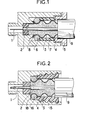
- FIG. 2 another example of fixing the cable end in the body of the connector is illustrated.
- the preceding references 1 to 4 designate the above-mentioned elements of the cable and of the connector
- the reference 9 designates the cable protection sheath.
- the fixing assembly always includes a sleeve reference 15, threaded onto the end of the outer conductor 3 with straight undulations, leaving here, a single terminal undulation, cooperating directly with an elastic ring 16 forcibly inserted at the bottom. of this terminal ripple.
- the sleeve 15 is advantageously a large molded rubber seal having externally a large thread and on which the body of the connector is directly screwed.
- the sleeve is also fixed, for example by gluing, on the end of the protective sheath 9.
- the sleeve 15 is fixed by snap-fastening in the body of the connector.
- the ring 6 or 16 may have a slit and be made from a round wire, or be formed by a circlip, or be made with any external shape as long as its elasticity remains sufficient to make it pass the first ridge of ripple and make it fall to the bottom of the first groove and as long as in position at the bottom of the ripple it comes into contact with the internal wall of the connector body without leaving the groove .
- the fixing assembly can comprise several rings such as 6 or 16, threaded to the bottom of the consecutive end corrugations left free by the sleeve coming to cooperate, directly or by means of an annular piece of longitudinal backlash covering one or more undulations, with the sleeve fixed in the body of the connector.
- the ring or rings used can be made of metal or elastomer.
- the play take-up piece can also be made of metal or elastomer or be a joint.
- the binding according to the invention is inexpensive, easy to produce and easy to assemble.
- the ring can also be constituted by a flat spring similar to the rings used in certain key rings and which are threaded by rotation while advancing the first turn of the spring after having moved it aside.
Landscapes
- Connector Housings Or Holding Contact Members (AREA)
- Coupling Device And Connection With Printed Circuit (AREA)
- Details Of Connecting Devices For Male And Female Coupling (AREA)
Abstract
Description
- La présente invention est relative au raccordement entre un câble à conducteur extérieur à ondulations droites et un connecteur.
- Il est connu de longue date que le raccordement peut se faire dans le cas d'une ondulation hélicoïdale au moyen d'une pièce métallique creuse avec un pas de vis intérieur au profil de l'ondulation.
- Dans le cas des câbles à conducteur extérieur à ondulations droites, il n'est plus possible d'utiliser cette disposition et on est obligé de réaliser deux demi-pièces fendues qui sont ensuite maintenues par une bague extérieure. Ce procédé, s'il est efficace, se montre relativement cher.
- Dans une autre disposition, on utilise une pièce présentant de nombreuses fentes périphériques permettant par effet d'élasticité, d'enfiler la pièce dans une gorge de la cannelure droite. Cette disposition nécessite une opération de fraisage chère.
- Le but de la présente invention est de procurer un raccordement ne nécessitant pas d'opération d'usinage longue et onéreuse.
- Elle a pour objet, un ensemble de fixation de l'extrémité d'un câble électrique à conducteur extérieur à ondulations droites dans le corps d'un connecteur, caractérisé en ce qu'il comporte
- - un manchon enfilé sur l'extrémité du conducteur extérieur à ondulations droites laissant dépasser au moins une ondulation terminale et se fixant dans le corps du connecteur
- - et au moins un anneau élastique inséré à force au fond d'une ondulation terminale et présentant une épaisseur telle que dans cette position il vienne au contact de la paroi interne du corps du connecteur lorsque l'extrémité du conducteur extérieur du câble est insérée dans le connecteur, ledit anneau servant de pièce d'appui au manchon pour assurer l'ancrage de l'extrémité du conducteur extérieur au fond du connecteur.
- Ainsi, conformément à la présente invention, on place dans l'une des gorges de l'ondulation droite un anneau élastique présentant une fente, cet anneau pouvant être réalisé à partir d'un fil rond, ou être constitué par un circlips, ou être réalisé avec un forme extérieure quelconque, du moment que son élasticité reste suffisante pour lui faire passer la première crête d'ondulation et le faire tomber dans la première gorge.
- On peut aussi placer deux ou plusieurs anneaux dans des gorges successives et, le cas échéant une pièce annulaire couvrant une, deux ou plusieurs pas de l'ondulation droite.
- Les anneaux peuvent être en métal ou en matière plastique.
- Deux exemples non limitatifs de fixation selon l'invention sont décrits ci-après et représentés dans les figures 1 et 2 du dessin annexé.
- Dans la figure 1, on a illustré l'extrémité d'un câble coaxial, dont on a représenté le conducteur central en 1 avec sa gaine 2 et le conducteur extérieur à ondulations droites ou soufflet en 3, fixé dans le corps d'un connecteur 4.
- L'ensemble de fixation comporte un manchon 5 enfilé sur l'extrémité du conducteur extérieur 3 en laissant dépasser au moins une ondulation terminale, ici deux ondulations. Ce manchon 5 est vissé dans le corps du connecteur dont la partie d'extrémité est taraudée, il est par ailleurs fixé, par exemple collé, sur l'extrémité d'une gaine extérieure 9 de protection du câble.
- Il comporte, en outre, un anneau élastique 6 inséré à force au fond de la première ondulation terminale et une pièce annulaire 7 de rattrapage de jeu en profondeur disposée autour du conducteur extérieur 3 entre l'anneau 6 et le manchon 5 venant avec l'anneau et la partie vissée du manchon se loger dans le corps du connecteur.
- L'anneau 6 est choisi d'épaisseur telle que positionné au fond de la première gorge terminale il vienne en contact avec la paroi interne du corps du connecteur lorsque l'extrémité de la gaine 3 est insérée dans le corps du connecteur, ledit anneau servant alors, par l'intermédiaire de la pièce 7 de rattrapage de jeu, de pièce d'appui au manchon 5 pour assurer l'ancrage de l'extrémité du conducteur extérieur 3 au fond du connecteur.
- Cette disposition permet un excellent contact électrique entre le corps du connecteur et le conducteur extérieur ondulé du câble coaxial, au point 8. La pièce de rattrapage de jeu 7, peut être avantageusement un joint d'étanchéité, en caoutchouc ou autre matériau tel que le polytétrafluoréthylène.
- Dans la figure 2 on a illustré un autre exemple de fixation de l'extrémité de câble dans le corps du connecteur.
- Dans cette figure les références précédentes 1 à 4 désignent les éléments cités ci-avant du câble et du connecteur, la référence 9 désigne la gaine de protection du câble. Dans ce cas l'ensemble de fixation comporte toujours un manchon référence 15, enfilé sur l'extrémité du conducteur extérieur 3 à ondulations droites en laissant dépasser, ici, une seule ondulation terminale, coopérant directement avec un anneau élastique 16 inséré à force au fond de cette ondulation terminale. Le manchon 15 est avantageusement un gros joint en caoutchouc moulé présentant extérieurement un gros pas de vis et sur lequel le corps du connecteur vient directement se visser. Le manchon est par ailleurs fixé, par exemple par collage, sur l'extrémité de la gaine de protection 9.
- En variante, le manchon 15 se fixe par encliquetage dans le corps du connecteur.
- Dans cette figure 2, au point d'ancrage de l'extrémité du conducteur extérieur 3 au fond du connecteur, référence 18, le fond du connecteur a été représenté droit. Il peut être bien entendu de toute autre forme convenable, telle que conique, ainsi qu'il est bien connu dans les connecteurs pour favoriser le meilleur contact possible. Il peut également être réalisé par collet battu ou repoussé.
- Dans chacun de ces deux exemples, l'anneau 6 ou 16 peut présenter une fente et être réalisé à partir d'un fil rond, ou être constitué par un circlips, ou être réalisé avec une forme extérieure quelconque du moment que son élasticité reste suffisante pour lui faire passer la première crête d'ondulation et le faire tomber au fond de la première gorge et du moment qu'en position au fond de l'ondulation il vienne en contact avec la paroi interne du corps de connecteur sans sortir de la gorge.
- En variante non illustrée,on comprendre aisément que l'ensemble de fixation peut comporter plusieurs anneaux tels que 6 ou 16, enfilés au fond des ondulations terminales consécutives laissées libres par le manchon venant coopérer, directement ou par l'intermédiaire d'une pièce annulaire de rattrapage de jeu longitudinal couvrant une ou plusieurs ondulations, avec le manchon fixé dans le corps du connecteur.
- Le ou les anneaux utilisés peuvent être en métal ou en élastomère. La pièce de rattrapage de jeu peut également être en métal ou en élastomère ou être un joint.
- La fixation selon l'invention est bon marché, aisée à réaliser et facile à monter.
- L'anneau peut aussi être constitué par un ressort plat analogue aux anneaux utilisés dans certains porte-clés et qui s'enfilent par rotation en faisant avancer la première spire du ressort après l'avoir écartée.
Claims (11)
Applications Claiming Priority (2)
| Application Number | Priority Date | Filing Date | Title |
|---|---|---|---|
| FR8016437 | 1980-07-25 | ||
| FR8016437A FR2487591A1 (fr) | 1980-07-25 | 1980-07-25 | Ensemble de fixation de l'extremite d'un cable electrique a gaine exterieure a ondulations droites dans le corps d'un connecteur |
Publications (2)
| Publication Number | Publication Date |
|---|---|
| EP0045038A1 true EP0045038A1 (fr) | 1982-02-03 |
| EP0045038B1 EP0045038B1 (fr) | 1985-10-23 |
Family
ID=9244544
Family Applications (1)
| Application Number | Title | Priority Date | Filing Date |
|---|---|---|---|
| EP19810105714 Expired EP0045038B1 (fr) | 1980-07-25 | 1981-07-21 | Ensemble de fixation de l'extrémité d'un câble électrique à conducteur extérieur à ondulations droites dans le corps d'un connecteur |
Country Status (4)
| Country | Link |
|---|---|
| EP (1) | EP0045038B1 (fr) |
| JP (1) | JPS5760681A (fr) |
| DE (1) | DE3172708D1 (fr) |
| FR (1) | FR2487591A1 (fr) |
Cited By (6)
| Publication number | Priority date | Publication date | Assignee | Title |
|---|---|---|---|---|
| US4464000A (en) * | 1982-09-30 | 1984-08-07 | The Bendix Corporation | Electrical connector assembly having an anti-decoupling device |
| ES2074960A2 (es) * | 1992-12-18 | 1995-09-16 | Bosch Gmbh Robert | Dispositivo de descarga de traccion para un cable electrico recubierto por extrusion. |
| EP0936703A3 (fr) * | 1998-02-17 | 2000-12-27 | Teracom Components Ab | Dispositif de contact |
| WO2006047907A1 (fr) * | 2004-11-08 | 2006-05-11 | Huber+Suhner Ag | Fiche de cable coaxial et procede pour monter une fiche de ce type |
| RU2677227C2 (ru) * | 2016-10-18 | 2019-01-16 | Акционерное общество "Ордена Трудового Красного Знамени Всероссийский научно-исследовательский институт радиоаппаратуры" (АО "ВНИИРА") | Соединитель высоковольтный |
| RU2715377C1 (ru) * | 2019-09-20 | 2020-02-27 | Российская Федерация, от имени которой выступает Государственная корпорация по атомной энергии "Росатом" (Госкорпорация "Росатом") | Разъемный соединитель |
Citations (5)
| Publication number | Priority date | Publication date | Assignee | Title |
|---|---|---|---|---|
| FR1094387A (fr) * | 1953-11-16 | 1955-05-20 | Conducto | Raccord étanche pour tuyaux et gaines métalliques flexibles |
| FR1234776A (fr) * | 1959-05-19 | 1960-10-19 | Dispositif de retenue d'une bague ou d'un raccord sur un tube annelé | |
| DE2252026A1 (de) * | 1972-10-24 | 1974-05-02 | Siemens Ag | Anschlusseinrichtung fuer koaxialkabel |
| FR2240540A1 (en) * | 1973-08-08 | 1975-03-07 | Bunker Ramo | Coaxial connector snaps together and has split ring - initially compressed into deep groove riding into shallow groove to lock halves together |
| BE825163A (fr) * | 1974-02-04 | 1975-08-04 | Dispositif de contact pour connexions de cables |
Family Cites Families (2)
| Publication number | Priority date | Publication date | Assignee | Title |
|---|---|---|---|---|
| JPS5592289U (fr) * | 1978-12-20 | 1980-06-26 | ||
| JPS5592288U (fr) * | 1978-12-20 | 1980-06-26 |
-
1980
- 1980-07-25 FR FR8016437A patent/FR2487591A1/fr active Granted
-
1981
- 1981-07-21 EP EP19810105714 patent/EP0045038B1/fr not_active Expired
- 1981-07-21 DE DE8181105714T patent/DE3172708D1/de not_active Expired
- 1981-07-24 JP JP56116315A patent/JPS5760681A/ja active Granted
Patent Citations (6)
| Publication number | Priority date | Publication date | Assignee | Title |
|---|---|---|---|---|
| FR1094387A (fr) * | 1953-11-16 | 1955-05-20 | Conducto | Raccord étanche pour tuyaux et gaines métalliques flexibles |
| FR1234776A (fr) * | 1959-05-19 | 1960-10-19 | Dispositif de retenue d'une bague ou d'un raccord sur un tube annelé | |
| DE2252026A1 (de) * | 1972-10-24 | 1974-05-02 | Siemens Ag | Anschlusseinrichtung fuer koaxialkabel |
| FR2240540A1 (en) * | 1973-08-08 | 1975-03-07 | Bunker Ramo | Coaxial connector snaps together and has split ring - initially compressed into deep groove riding into shallow groove to lock halves together |
| BE825163A (fr) * | 1974-02-04 | 1975-08-04 | Dispositif de contact pour connexions de cables | |
| DE2405241A1 (de) * | 1974-02-04 | 1975-08-14 | Siemens Ag | Kontakteinrichtung fuer kabelanschluesse |
Cited By (12)
| Publication number | Priority date | Publication date | Assignee | Title |
|---|---|---|---|---|
| US4464000A (en) * | 1982-09-30 | 1984-08-07 | The Bendix Corporation | Electrical connector assembly having an anti-decoupling device |
| ES2074960A2 (es) * | 1992-12-18 | 1995-09-16 | Bosch Gmbh Robert | Dispositivo de descarga de traccion para un cable electrico recubierto por extrusion. |
| EP0936703A3 (fr) * | 1998-02-17 | 2000-12-27 | Teracom Components Ab | Dispositif de contact |
| AU737231B2 (en) * | 1998-02-17 | 2001-08-16 | Teracom Components Ab | Contact device |
| WO2006047907A1 (fr) * | 2004-11-08 | 2006-05-11 | Huber+Suhner Ag | Fiche de cable coaxial et procede pour monter une fiche de ce type |
| US7462069B2 (en) | 2004-11-08 | 2008-12-09 | Huber+Suhner Ag | Cable plug for a coaxial cable and method for mounting a cable plug of this type |
| AU2005301003B2 (en) * | 2004-11-08 | 2009-09-17 | Huber+Suhner Ag | Cable plug for a coaxial cable and method for mounting a cable plug of this type |
| RU2383091C2 (ru) * | 2004-11-08 | 2010-02-27 | Хубер+Зунер АГ | Кабельный соединитель для коаксиального кабеля и способ крепления такого кабельного соединения |
| CN101048918B (zh) * | 2004-11-08 | 2013-06-26 | 胡贝尔和茹纳股份公司 | 同轴电缆的电缆插头和这样的电缆插头的组装方法 |
| RU2677227C2 (ru) * | 2016-10-18 | 2019-01-16 | Акционерное общество "Ордена Трудового Красного Знамени Всероссийский научно-исследовательский институт радиоаппаратуры" (АО "ВНИИРА") | Соединитель высоковольтный |
| RU2715377C1 (ru) * | 2019-09-20 | 2020-02-27 | Российская Федерация, от имени которой выступает Государственная корпорация по атомной энергии "Росатом" (Госкорпорация "Росатом") | Разъемный соединитель |
| RU2715377C9 (ru) * | 2019-09-20 | 2020-04-29 | Российская Федерация, от имени которой выступает Государственная корпорация по атомной энергии "Росатом" (Госкорпорация "Росатом") | Разъемный соединитель |
Also Published As
| Publication number | Publication date |
|---|---|
| EP0045038B1 (fr) | 1985-10-23 |
| DE3172708D1 (en) | 1985-11-28 |
| FR2487591A1 (fr) | 1982-01-29 |
| JPS5760681A (en) | 1982-04-12 |
| JPH0216552B2 (fr) | 1990-04-17 |
| FR2487591B1 (fr) | 1983-10-21 |
Similar Documents
| Publication | Publication Date | Title |
|---|---|---|
| EP0196931B1 (fr) | Commande mécanique à câble à réglage automatique | |
| CA1329420C (fr) | Connecteur electrique | |
| US6994588B2 (en) | Compression connector for coaxial cable and method of installation | |
| FR2612343A1 (fr) | Connecteur pour une ligne coaxiale a conducteur exterieur ondule ou pour un guide d'ondes a tube ondule | |
| EP1203431B1 (fr) | Dispositif de retenue axiale d'un l ment cylindrique et plus particuli rement un c ble | |
| EP0663706A1 (fr) | Connecteur coaxial microminiature à verrouillage par encliquetage | |
| FR2513821A1 (fr) | ||
| FR2638290A1 (fr) | Raccord pour cable coaxial | |
| FR2673332A1 (fr) | Perfectionnements apportes aux connecteurs. | |
| EP0045038A1 (fr) | Ensemble de fixation de l'extrémité d'un câble électrique à conducteur extérieur à ondulations droites dans le corps d'un connecteur | |
| EP0037313B1 (fr) | Perfectionnements aux dispositifs permettant l'étanchéité des connecteurs électriques | |
| FR2662772A1 (fr) | Temoin d'usure pour garniture de friction. | |
| FR2579837A1 (fr) | Serre-cable pour installations electriques | |
| EP0206896A1 (fr) | Presse-étoupe modulaire et adaptable à la traversée d'une paroi par une canalisation cylindrique | |
| EP0862801B1 (fr) | Piece de raccordement electrique | |
| FR2777711A1 (fr) | Capuchon de connexion pour bougie d'allumage et procede pour sa fabrication | |
| FR2543369A2 (fr) | Dispositif d'etancheite pour connecteur electrique | |
| FR2594205A1 (fr) | Raccord terminal de tuyau souple | |
| CA2238260C (fr) | Piece de raccordement electrique | |
| FR2584476A1 (fr) | Raccord de conduit | |
| FR2729010A1 (fr) | Antenne pour vehicule automobile susceptible de recevoir un adaptateur actif d'impedance et ensemble adaptateur actif d'impedance pour une telle antenne | |
| FR2545206A1 (fr) | Dispositif d'amorcage electrique a percussion pour cones de combat | |
| EP0328467A1 (fr) | Cosse de connexion électrique | |
| EP1854178B1 (fr) | Connecteur universel pour cable coaxial | |
| EP0683556A1 (fr) | Structure de liaison électrique d'un manchon protecteur avec une extrémité d'un écran semi-conducteur d'un câble électrique |
Legal Events
| Date | Code | Title | Description |
|---|---|---|---|
| PUAI | Public reference made under article 153(3) epc to a published international application that has entered the european phase |
Free format text: ORIGINAL CODE: 0009012 |
|
| AK | Designated contracting states |
Designated state(s): BE CH DE FR GB IT NL SE |
|
| 17P | Request for examination filed |
Effective date: 19820723 |
|
| ITF | It: translation for a ep patent filed | ||
| GRAA | (expected) grant |
Free format text: ORIGINAL CODE: 0009210 |
|
| AK | Designated contracting states |
Designated state(s): BE CH DE FR GB IT LI NL SE |
|
| REF | Corresponds to: |
Ref document number: 3172708 Country of ref document: DE Date of ref document: 19851128 |
|
| PLBE | No opposition filed within time limit |
Free format text: ORIGINAL CODE: 0009261 |
|
| STAA | Information on the status of an ep patent application or granted ep patent |
Free format text: STATUS: NO OPPOSITION FILED WITHIN TIME LIMIT |
|
| 26N | No opposition filed | ||
| ITTA | It: last paid annual fee | ||
| EAL | Se: european patent in force in sweden |
Ref document number: 81105714.0 |
|
| PGFP | Annual fee paid to national office [announced via postgrant information from national office to epo] |
Ref country code: CH Payment date: 19950428 Year of fee payment: 15 |
|
| PGFP | Annual fee paid to national office [announced via postgrant information from national office to epo] |
Ref country code: SE Payment date: 19950524 Year of fee payment: 15 |
|
| PGFP | Annual fee paid to national office [announced via postgrant information from national office to epo] |
Ref country code: FR Payment date: 19950529 Year of fee payment: 15 Ref country code: DE Payment date: 19950529 Year of fee payment: 15 |
|
| PGFP | Annual fee paid to national office [announced via postgrant information from national office to epo] |
Ref country code: BE Payment date: 19950602 Year of fee payment: 15 |
|
| PGFP | Annual fee paid to national office [announced via postgrant information from national office to epo] |
Ref country code: GB Payment date: 19950615 Year of fee payment: 15 |
|
| PGFP | Annual fee paid to national office [announced via postgrant information from national office to epo] |
Ref country code: NL Payment date: 19950728 Year of fee payment: 15 |
|
| PG25 | Lapsed in a contracting state [announced via postgrant information from national office to epo] |
Ref country code: GB Effective date: 19960721 |
|
| PG25 | Lapsed in a contracting state [announced via postgrant information from national office to epo] |
Ref country code: SE Effective date: 19960722 |
|
| PG25 | Lapsed in a contracting state [announced via postgrant information from national office to epo] |
Ref country code: LI Effective date: 19960731 Ref country code: CH Effective date: 19960731 Ref country code: BE Effective date: 19960731 |
|
| BERE | Be: lapsed |
Owner name: LES CABLES DE LYON Effective date: 19960731 |
|
| PG25 | Lapsed in a contracting state [announced via postgrant information from national office to epo] |
Ref country code: NL Effective date: 19970201 |
|
| GBPC | Gb: european patent ceased through non-payment of renewal fee |
Effective date: 19960721 |
|
| REG | Reference to a national code |
Ref country code: CH Ref legal event code: PL |
|
| PG25 | Lapsed in a contracting state [announced via postgrant information from national office to epo] |
Ref country code: FR Effective date: 19970328 |
|
| NLV4 | Nl: lapsed or anulled due to non-payment of the annual fee |
Effective date: 19970201 |
|
| PG25 | Lapsed in a contracting state [announced via postgrant information from national office to epo] |
Ref country code: DE Effective date: 19970402 |
|
| EUG | Se: european patent has lapsed |
Ref document number: 81105714.0 |
|
| REG | Reference to a national code |
Ref country code: FR Ref legal event code: ST |