EP0045043A2 - Kanalanschlusssteuerung - Google Patents
Kanalanschlusssteuerung Download PDFInfo
- Publication number
- EP0045043A2 EP0045043A2 EP81105745A EP81105745A EP0045043A2 EP 0045043 A2 EP0045043 A2 EP 0045043A2 EP 81105745 A EP81105745 A EP 81105745A EP 81105745 A EP81105745 A EP 81105745A EP 0045043 A2 EP0045043 A2 EP 0045043A2
- Authority
- EP
- European Patent Office
- Prior art keywords
- control
- data
- multiplex
- channel
- memory
- Prior art date
- Legal status (The legal status is an assumption and is not a legal conclusion. Google has not performed a legal analysis and makes no representation as to the accuracy of the status listed.)
- Granted
Links
Images


Classifications
-
- G—PHYSICS
- G06—COMPUTING OR CALCULATING; COUNTING
- G06F—ELECTRIC DIGITAL DATA PROCESSING
- G06F13/00—Interconnection of, or transfer of information or other signals between, memories, input/output devices or central processing units
- G06F13/10—Program control for peripheral devices
- G06F13/12—Program control for peripheral devices using hardware independent of the central processor, e.g. channel or peripheral processor
- G06F13/122—Program control for peripheral devices using hardware independent of the central processor, e.g. channel or peripheral processor where hardware performs an I/O function other than control of data transfer
Definitions
- the invention relates to a multiplex channel connection controller according to the preamble of the main claim.
- Peripheral devices are operated by device controls which, in a known manner, have a direct connection to a multiplex channel via a channel interface.
- Such controls can either be a single device or one of several connected devices in single operation, i.e. Operate selector mode or multiple devices simultaneously in multiplex mode.
- the multiplex channel required for this is connected, for example, via a central bus to a preferably micro-programmed input / output processor, in which the input and output operations common to all peripheral devices run. In particular, this relates to the communication with the central processor in which the work program runs, the continuation of chaining operations and the conclusion of traffic.
- the multiplex channel essentially performs a switching function and adapts to the channel interface for these operations.
- the present invention is based on the knowledge that the control for data transport takes comparatively less time than the interface.
- the object of the invention is therefore to show a way in which the overall data throughput of a multiplex channel can be optimized as far as possible.
- a total data throughput should be achieved in a multiplex channel with simultaneous operation of several or all devices, which is higher than could be achieved by stringing together the individual interface cycles.
- the traffic over the individual interface connections should be able to run selectively and independently of the traffic on the other connections in the selector or multiplex mode.
- Such a multiplex channel connection controller has the advantage that the channel controller can be released before the interface cycle expires for the handling of a data transport. As a result, a total data rate can be achieved with a common device controller, which is higher than would be achieved with a reservation of the controller for a full interface cycle in each case.
- the data processing system consists of a central processor, not shown in the drawing, which is connected to an input / output processor IOP via control lines, and a central working memory AS, which in addition to the programs for the central processor and input / output processor, communication cells for transferring information between the two Contains processors.
- the input / output processor IOP is in turn connected to a multiplex channel MUX, possibly further devices EG of the same or similar type and to a memory traffic control ZUW, which handles the traffic with the working memory AS for the input / output processor IOP and its additional devices.
- An input / output processor IOP, multiplex channel MUX, memory traffic control ZUW and any additional devices are connected via a central bus, which consists of a control part C-BUS and a data part D-BUS.
- the bus becomes connected Allocated facilities on request from a central administration located in the I / O processor for a processing cycle.
- the MUX multiplex channel is connected via individual cable connections to a number of device controls GS1 ... GS8, to which the peripheral devices P1 ... PZ are connected.
- the device controls can belong to any of the three basic types. In the exemplary embodiment shown, the device controller GS8 is a single device controller to which only one device is connected. This device control therefore only works in selector mode.
- the device control GS2 has two devices Px and Py, one of which is selected when the traffic is initiated, ie is selected and is in operation until the traffic is closed. This device control GS2 therefore also works in selector mode.
- the device controller GS1 is a multiple controller in which several devices P1 ... Pn can be in operation at the same time. Data from a wide variety of devices therefore flow via the channel interface in an arbitrary mixture corresponding to the device types. For each data character, possibly also for a group of characters belonging together, the identification of the associated device is therefore necessary, which takes place in an additional addressing cycle via the interface.
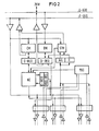
- the multiplex channel MUX has a fast control memory CM. Two control words are provided in it for each connection. The first control word is used for ongoing traffic. The second control word is set up if the transport capacity of the first control word is insufficient for the relevant input / output command or if a further section is immediate to be chained. After the first control word has been processed, the channel then switches directly to the second and, as a precaution, requests further control information from the input / output processor IOP, so that there are no operating gaps even with high data rates of a device.
- the data transmitted via the channel interface are temporarily stored in a data buffer DM belonging to the relevant connection, which in the exemplary embodiment has a capacity of four bytes, corresponding to the width of the central data bus D-BUS.
- the memory traffic control ZUW requests another data word which has been fetched from the main memory by a so-called prefetch operation.
- a full data buffer word is transferred to the memory traffic control, which buffers this data and transfers it to the main memory after a storage condition has been reached.
- the memory traffic control also ensures that there is a minimum supply of data for forwarding to the multiplex channel MUX, so that requests from the multiplex channel can be met directly from this supply.
- a pre-fetch operation is used to replenish the stock.
- Data transport requests can arrive from several or all connected device controls at the same time. According to a predetermined ranking or priority, a request is selected by a priority and selection control PAS and the relevant control word is read out.
- An address pointer selects the respectively active control word from the two possible control words, which is transferred to the control register C REG.
- the control word contains, among other things, the device address, a section length counter, an address pointer for the respectively valid byte position in the data buffer DM, a coded display for writing, reading forwards and reading backwards, as well as positions for the registration of detected errors.
- a bit position contains a validity indicator that is deleted from the channel when the last byte for this control word is transmitted. When it is output, the data byte identified by the address pointer is transmitted via the interface, together with the control signals defined for the interface.
- the incoming byte is entered in the register position identified by the address pointer and execution is acknowledged by transferring the appropriate interface signals to the device control.
- the section length counter is decremented in each case and the address pointer for the data buffer DM is reset. The control word and data word are then written back to the memory.
- the channel initiates an access to the memory traffic control in order to pick up a new word and to enter it in the buffer memory or to feed the input data word into the memory traffic control transmitted before the control word and data word are written back to their corresponding storage stations.
- An additional operation is performed when the section length counter is exhausted. If the control word indicates that no further transmission follows, an END identifier is transmitted to the device control together with the other interface signals. If further data transports are to follow, the tax word address pointer switched so that the alternative control word is activated for the next data transport.
- a data word is additionally obtained from the storage traffic control ZUW on the basis of the new control word, so that valid data is already available when the next data request is made.
- further control information is requested from the input / output processor IOP so that it can be reloaded by the input / output processor IOP in good time before switching again. For the request, a status word with the corresponding identification is generated by the channel controller KC and entered into the status memory STM, from which it is read out by the input / output processor.
- the processing of the data requests for the channel control KC ends with the write-back in the control and data memory CM, DM. Due to the signaling conventions for the interface, the signals have to be maintained for some time. So that a high overall data rate can be achieved, the channel control KC is released after the write-back, so that a request from another connection can be taken over for processing.
- the interface-specific signaling is carried out by an adapter circuit provided for each connection, which ensures correct signal measurement.
- FIG. 3 The overlapping mode of operation possible due to the premature release of the channel control KC is shown in FIG. 3 for three connections, for example. It shows in each case for a connection A, 1, A2, to the time TSP1, 2 ... n for the synchronization and priority selection, furthermore the time TIS1, 2 ... n for the interface signal measurement, also the respective occupancy time TBA1, 2 ... n of the channel control per connection and finally the time of release (upward arrowhead) for the selection of a new request and the respective End of channel control assignment per connection (see the arrow pointing downwards). From this representation it can be seen that the processing of a request on another connection is already released while the signaling cycle on the first connection is still ongoing.
- the described direct processing of data traffic with the peripheral devices is possible for one device per device control. If another device is to be put into operation by a device controller, the relevant connection is switched over by the input / output processor IOP to multiplex mode. For this purpose, a control bit is provided in a multiplex mode register MUX-REG, which can be set and erased and determines the operating mode of the connection concerned.
- the cycle interfaces retrieves the associated in an additional device address of the device controller and compares it with the 'address that is registered in the control memory CM for that terminal. If both addresses match, the data transport is handled directly, as described above. If the addresses do not match, the data transport request is forwarded to the input / output processor IOP, where it is processed by microprocesses. The information required for this is sent to the input / output processor IOP communicated in the form of a status statement which, in addition to the identifier for the data transport, contains the number of the connection concerned, the address of the device to be operated and the data character adopted by the interface.
- the microprogram decides whether such a data character is a valid input character based on control information.
- the status information is entered in a status memory STM and the multiplex controller C-MUX is released for a further interface process. The status can then be adopted by the input / output processor independently of the interface processes.
Landscapes
- Engineering & Computer Science (AREA)
- Theoretical Computer Science (AREA)
- Physics & Mathematics (AREA)
- General Engineering & Computer Science (AREA)
- General Physics & Mathematics (AREA)
- Data Exchanges In Wide-Area Networks (AREA)
- Use Of Switch Circuits For Exchanges And Methods Of Control Of Multiplex Exchanges (AREA)
- Time-Division Multiplex Systems (AREA)
- Vehicle Body Suspensions (AREA)
Abstract
Description
- Die Erfindung bezieht sich auf eine Multiplex-Kanalanschluß-Steuerung gemäß dem Oberbegriff des Hauptanspruchs.
- Peripheriegeräte werden von Gerätesteuerungen betrieben, die in bekannter Weise über eine Kanalschnittstelle einen direkten Anschluß zu einem Multiplex-Kanal haben. Derartige Steuerungen können dabei wahlweise ein Einzelgerät oder eines von mehreren angeschlossenen Geräten im Einzelbetrieb, d.h. Selektorbetrieb oder mehrere Geräte simultan im Multiplexbetrieb bedienen. Der hierzu benötigte Multiplexkanal ist beispielsweise über einen zentralen Bus an einen vorzugsweise mikroprogrammierten Ein/Ausgabeprozessor angeschlossen, in dem die allen Peripheriegeräten gemeinsamen Ein- und Ausgabeoperationen ablaufen. Es handelt sich dabei insbesondere um den Verkehr mit dem Zentralprozessor, in dem das Arbeitsprogramm abläuft, weiterhin um die Fortschaltung bei Kettungsoperationen und um den Verkehrsabschluß. Für diese Operationen übt der Multiplexkanal im wesentlichen eine Vermittlungsfunktion und die Anpassung an die Kanalschnittstelle aus.
- Der Datenverkehr zwischen dem Ein/Ausgabeprozessor und den einzelnen Peripheriegeräten erfolgt nun in der Weise, daß die Peripheriegeräte aufgrund von Anforderungssignalen bedient werden, die von der jeweils zugehörigen Gerätesteuerung an den Multiplexkanal gesendet werden.
- Über eine Prioritäts- und Auswahlschaltung im Kanal werden dann seine Einrichtungen für einen Schnittstellenzyklus einer Gerätesteuerung zugewiesen und anschliessend wieder freigegeben.
- Die vorliegende Erfindung geht nun von der Erkenntnis aus, daß die Steuerung für einen Datentransport vergleichsweise weniger Zeit braucht als die Schnittstelle. Der Erfindung liegt deshalb die Aufgabe zugrunde, einen Weg aufzuzeigen, wie der Gesamtdatendurchsatz eines Multiplexkanals möglichst optimiert werden kann. Unter der gegebenen Voraussetzung einer durch die Kanalschnittstelle gegebenen minimalen Bedienungs- und Ablaufdauer für einen Datentransport von einem Byte soll in einem Multiplexkanal bei gleichzeitigem Betrieb mehrerer oder aller Geräte ein Gesamtdatendurchsatz erbracht werden, der höher liegt als sich durch das Aneinanderreihen der einzelnen Schnittstellenzyklen erreichen ließe. Der Verkehr über die einzelnen Schnittstellenanschlüsse soll dabei wahlweise und unabhängig vom Verkehr auf den anderen Anschlüssen im Selektor- oder Multiplexmodus ablaufen können.
- Diese Aufgabe wird erfindungsgemäß mit den kennzeichnenden Merkmalen des Hauptanspruchs gelöst. Mit einer derartigen Multiplex-Kanalanschluß-Steuerung ergibt sich der Vorteil, daß für die Abkwicklung eines Datentransports die Kanalsteuerung bereits vor Ablauf des Schnittstellenzyklus freigegeben werden kann. Dadurch läßt sich mit einer gemeinsamen Gerätesteuerung eine Gesamtdatenrate erzielen, die höher liegt als sie mit einer Reservierung der Steuerung für jeweils einen vollen Schnittstellenzyklus zu erreichen wäre.
- Vorteilhafte Weiterbildungen der Erfindung sind in den Unteransprüchen angegeben.
- Ein Ausführungsbeispiel der Erfindung wird im folgenden anhand der Zeichnung näher erläutert.
- Dabei zeigen:
- FIG 1 den prinzipiellen Aufbau einer Datenverarbeitungsanlage mit Multiplex-Kanal anhand eines Blockschaltbildes,
- FIG 2 Einzelheiten eines Multiplex-Kanals zur Verwendung in einer Schaltung gemäß FIG 1,
- FIG 3 ' das Zeitraster für drei Anschlüsse im Falle gleichzeitig eintreffender Datentransportanforderungen.
- Die Datenverarbeitungsanlage gemäß FIG 1 besteht aus einem in der Zeichnung nicht dargestellten Zentralprozessor, der über Steuerleitungen mit einem Ein/Ausgabeprozessor IOP verbunden ist, sowie aus einem zentralen Arbeitsspeicher AS, der neben den Programmen für Zentranlprozessor und Ein/Ausgabeprozessor Kommunikationszellen zur Informationsübergabe zwischen den beiden Prozessoren enthält. Der Ein/Ausgabeprozessor IOP ist seinerseits mit einem Multiplexkanal MUX, eventuell weiteren Einrichtungen EG gleicher oder ähnlicher Art und mit einer Speicherverkehrssteuerung ZUW verbunden, die für den Ein/Ausgabeprozessor IOP und seine Zusatzeinrichtungen den Verkehr mit dem Arbeitsspeicher AS abwickelt. Ein/Ausgabeprozessor IOP,Multiplexkanal MUX, Speicherverkehrssteuerung ZUW und eventuelle Zusatzeinrichtungen sind über einen zentralen Bus verbunden, der aus einem Steuerteil C-BUS und einem Datenteil D-BUS besteht. Der Bus wird den angeschlossenen Einrichtungen auf Anforderung von einer im Ein/Ausgabeprozessor lokalisierten zentralen Verwaltung für einen Abwicklungszyklus zugeteilt. Der Multiplexkanal MUX ist über individuelle Kabelverbindungen mit einer Anzahl von Gerätesteuerungen GS1...GS8 verbunden, an die ihrerseits die Peripheriegeräte P1...PZ angeschlossen sind. Die Gerätesteuerungen können beliebig einem der drei grundsätzlichen Typen angehören. Im dargestellten Ausführungsbeispiel ist die Gerätesteuerung GS8 eine Einzelgerätesteuerung, an die nur ein Gerät angeschlossen ist. Diese Gerätesteuerung arbeitet daher ausschließlich im Selektormodus. Die Gerätesteuerung GS2 verfügt über zwei Geräte Px und Py, von denen eines bei der Verkehrseinleitung ausgewählt, d.h. selektiert wird und bis zum Verkehrsabschluß allein in Betrieb ist. Diese Gerätesteuerung GS2 arbeitet daher ebenfalls im Selektormodus. Die Gerätesteuerung GS1 ist dagegen eine Mehrfachsteuerung, bei der mehrere Geräte P1...Pn gleichzeitig in Betrieb sein können. Über die Kanalschnittstelle fließen daher in einer den Gerätetypen entsprechenden willkürlichen Mischung Daten der verschiedensten Geräte. Für jedes Datenzeichen, gegebenenfalls auch für eine Gruppe von zusammengehörigen Zeichen, ist daher die Kennzeichnung des zugehörigen Gerätes erforderlich, die in einem zusätzlichen Adressierungszyklus über die Schnittstelle erfolgt.
- Einzelheiten des Multiplexkanals MUX sind in FIG 2 dargestellt. Der Multiplexkanal MUX verfügt über einen schnellen Steuerspeicher CM. In ihm sind für jeden Anschluß zwei Steuerworte vorgesehen. Das erste Steuerwort dient dem laufenden Verkehr. Das zweite Steuerwort wird eingerichtet, wenn die Transportkapazität des ersten Steuerwortes für den betreffenden Ein/Ausgabebefehl nicht ausreicht oder wenn ein weiterer Abschnitt unmittelbar angekettet werden soll. Der Kanal schaltet dann nach Abarbeitung des ersten Steuerwortes direkt auf das zweite um und fordert vorsorglich'vom Ein/Ausgabeprozessor IOP weitere Steuerinformation an, so daß auch bei hohen Datenraten eines Gerätes keine Bedienungslücken entstehen.
- Die über die Kanalschnittstelle übertragenen Daten werden in einem zu dem betreffenden Anschluß gehörenden Datenpuffer DM zwischengespeichert, der im Ausführungsbeispiel eine Kapazität von vier Bytes hat, entsprechend der Breite des zentralen Datenbusses D-BUS. Wenn bei Ausgabeoperationen ein Pufferwort leer geworden ist, wird von der Speicherverkehrssteuerung ZUW ein weiteres Datenwort angefordert, das durch eine sogenannte Prefetch-Operation aus dem Arbeitsspeicher geholt worden ist. Bei Eingabeoperationen wird ein volles Datenpufferwort an die Speicherverkehrssteuerung übertragen, die diese Daten zwischenpuffert und nach Erreichen einer Abspeicherbedingung an den Arbeitsspeicher überträgt. Bei Ausgabeoperationen sorgt die Speicherverkehrssteuerung außerdem dafür, daß ein Mindestvorrat an Daten für die Weitergabe an den Multiplexkanal MUX vorhanden ist, so daß Anforderungen vom Multiplexkanal unmittelbar aus diesem Vorrat befriedigt werden können. Sobald der Vorrat unter eine vorgegebene Pegelmarke gesunken ist, wird mit einer Pre-fetch-Operation für das Auffüllen des Vorrates gesorgt.
- Datentransportanforderungen können von mehreren oder allen angeschlossenen Gerätesteuerungen gleichzeitig eintreffen. Nach einer vorgegebenen Rangordnung bzw. Priorität wird durch eine Prioritäts- und Auswahlsteuerung PAS eine Anforderung ausgewählt und das betreffende Steuerwort ausgelesen. Ein Adreßzeiger wählt unter den beiden möglichen Steuerworten das jeweils aktive Steuerwort aus, das in das Steuerregister C REG übernommen wird. Das Steuerwort'enthält u.a. die Geräteadresse, einen Abschnittlängenzähler, einen Adreßzeiger für die jeweils gültige Byteposition im Datenpuffer DM, eine codierte Anzeige für Schreiben, Lesen vorwärts und Lesen rückwärts, dazu Positionen für die Eintragung erkannter Fehler. Eine Bitposition enthält eine Gültigkeitsanzeige, die vom Kanal gelöscht wird, wenn das letzte Byte für dieses Steuerwort übertragen wird. Bei Ausgabe wird das vom Adreßzeiger gekennzeichnete Datenbyte über die Schnittstelle übertragen, zusammen mit den für die Schnittstelle definierten Steuersignalen.
- Bei Eingabe wird entsprechend das ankommende Byte in die vom Adreßzeiger gekennzeichnete Registerposition eingetragen und die Ausführung durch Übergabe der entsprechenden Schnittstellensignale an die Gerätesteuerung quittiert. Der Abschnittslängenzähler wird jeweils dekrementiert und der Adreßzeiger für den Datenpuffer DM neu eingestellt. Steuerwort und Datenwort werden anschliessend in die Speicher zurückgeschrieben.
- Wenn bei Ausgabe ein Datenpufferwort leer geworden ist, bzw. bei Eingabe ein Wort voll wird, leitet der Kanal einen Zugriff an die Speicher-Verkehrssteuerung ein, um ein neues Wort abzuholen und in den Pufferspeicher einzutragen bzw. das Eingabedatenwort in die Speicher- Verkehrssteuerung zu übertragen, bevor Steuerwort und Datenwort in ihre entsprechenden Speicherstationen zurückgeschrieben werden.
- Eine zusätzliche Operation wird ausgeführt, wenn der Abschnittlängenzähler erschöpft ist. Wenn im Steuerwort angezeigt ist, daß keine weitere Übertragung folgt, wird zusammen mit den übrigen Schnittstellensignalen eine ENDE-Kennung an die Gerätesteuerung übertragen. Wenn weitere Datentransporte folgen sollen, wird der Steuerwortadreßzeiger umgeschaltet, so daß für den nächsten Datentransport das alternative Steuerwort aktiviert wird. Bei Ausgabeoperationen wird zusätzlich aufgrund des neuen Steuerwortes ein Datenwort aus der Speicherverkehrssteuerung ZUW beschafft, damit bei der nächsten Datenanforderung bereits gültige Daten vorhanden sind. In beiden Fällen wird außerdem vom Ein/Ausgabeprozessor IOP weitere Steuerinformation angefordert, damit sie rechtzeitig vor dem erneuten Umschalten durch den Ein/Ausgabeprozessor IOP nachgeladen werden kann. Für die Anforderung wird von der Kanalsteuerung KC ein Statuswort mit entsprechender Kennzeichnung generiert und in den Statusspeicher STM eingetragen, aus dem es vom Ein/Ausgabeprozessor ausgelesen wird.
- In den Fällen, in denen keine Speicherverkehrssteuerungzyklen erforderlich sind, ist für die Kanalsteuerung KC die Bearbeitung der Datenanforderungen mit dem Rückschreiben in Steuer- und Datenspeicher CM, DM beendet. Aufgrund der Signalisierungskonventionen für die Schnittstelle müssen die Signale noch für einige Zeit aufrechterhalten werden. Damit eine hohe Gesamtdatenrate erreicht werden kann, wird jedoch die Kanalsteuerung KC bereits nach dem Rückschreiben.freigegeben, so daß eine Anforderung von einem anderen Anschluß zur Bearbeitung übernommen werden kann. Die schnittstellenspezifische Signalisierung wird von einer für jeden Anschluß vorgesehenen Adapterschaltung übernommen, die für eine korrekte Signalvermaßung sorgt.
- Die durch die vorzeitige Freigabe der Kanalsteuerung KC mögliche überlappende Betriebsweise ist in FIG 3 für beispielsweise drei Anschlüsse dargestellt. Sie zeigt jeweils für einen Anschluß A,1, A2, An die Zeit TSP1, 2...n für die Synchronisierung und Prioritätsauswahl, ferner die Zeit TIS1, 2...n für die Schnittstellen-Signalvermaßung, außerdem die jeweilige Belegungszeitdauer TBA1, 2...n der Kanalsteuerung pro Anschluß und schließlich den Freigabezeitpunkt (nach oben gerichtete Pfeilspitze) für die Auswahl einer neuen Anforderung sowie das jeweilige Ende der Kanalsteuerungsbelegung pro Anschluß (siehe den nach unten gerichteten Pfeil). Aus dieser Darstellung ist ersichtlich, daß die Bearbeitung einer Anforderung auf einem anderen Anschluß bereits freigegeben wird, während der Signalisierungszyklus auf dem ersten Anschluß noch andauert.
- Die beschriebene direkte Abwicklung des Datenverkehrs mit den Peripheriegeräten ist für jeweils ein Gerät pro Gerätesteuerung möglich. Wenn von einer Gerätesteuerung ein weiteres Gerät in Betrieb genommen werden soll, wird der betreffende Anschluß vom Ein/Ausgabeprozessor IOP auf Multiplexmodus umgeschaltet. Für diesen Zweck ist in einem Multiplex-Modus-Register MUX-REG ein Steuerbit vorgesehen, das setz- und löschbar ist und den Operationsmodus des betreffenden Anschlusses bestimmt.
- Im Multiplexmodus ist für jeden Datentransport die Identifizierung des betreffenden Gerätes erforderlich. Über das Multiplex-Steuerbit wird eine Steuerung C-MUX aktiviert, die in einem zusätzlichen Schnittstellen-Zyklus die zugehörige Geräteadresse aus der Gerätesteuerung abruft und mit der'Adresse vergleicht, die im Steuerspeicher CM für den betreffenden Anschluß eingetragen ist. Bei Übereinstimmung beider Adressen wird der Datentransport, wie oben beschrieben, direkt abgewickelt. Wenn die Adressen nicht übereinstimmen, wird die Datentransportanforderung an den Ein/Ausgabeprozessor IOP weitergeleitet und dort durch Mikroproabläufe abgehandelt. Die dazu benötigte Information wird dem Ein/Ausgabeprozessor IOP in Form einer Statusangabe mitgeteilt, die neben der Kennung für den Datentransport die Nummer des betreffenden Anschlusses, die Adresse des zu bedienenden Gerätes und das von der Schnittstelle übernommene Datenzeichen enthält. Ob ein solches Datenzeichen ein gültiges Eingabezeichen ist, wird aufgrund von Steuerinformationen durch das Mikroprogramm entschieden. Um die Schnittstellenabläufe von der Reaktionszeit des Ein/Ausgabeprozessors IOP zu entkoppeln, wird die Statusinformation in einen Statusspeicher STM eingetragen und die Multiplexsteuerung C-MUX für einen weiteren Schnittstellenablauf freigegeben. Die Übernahme des Status durch den Ein/Ausgabeprozessor kann dann unabhängig von den Schnittstellenabläufen erfolgen.
Claims (1)
- Multiplex-Kanalanschluß-Steuerung für eine Datenverarbeitungsanlage, bestehend aus einem Zentralprozessor, einem Arbeitsspeicher und einem mit dem Zentralprozessor über ein zentrales Bus-System verbundenen, den Datenverkehr mit mehreren Peripheriegeräten abwickelnden Ein/ Ausgabeprozessor, bei der die einzelnen Kanäle über eine Kanalschnittstelle mit entsprechend vielen Gerätesteuerungen verbunden sind, an die ihrerseits ein oder mehrere Peripheriegeräte angeschlossen sind, dadurch gekennzeichnet , daß jedem Schnittstellenkanal ein Steuerspeicher (CM) für jeweils zwei im Wechselpufferverfahren arbeitende Steuerworte und ein Datenpuffer (DM) mit einer der Breite des zentralen Datenbusses (D-Bus) entsprechenden Kapazität zugeordnet sind, daß ein Multiplex-Modus-Register (MUX-REG) vorgesehen ist, in dem ein die Umschaltung des jeweiligen Schnittstellenkanals bewirkendes Steuerbit einspeicherbar ist und daß in einer durch das Steuerbit aktivierten Multiplex-Modus-Steuerung (C-MUX) ein Vergleich zwischen der Adresse eines Peripheriegerätes mit der im Steuerspeicher für den jeweils betreffenden, zur zugehörigen Gerätesteuerung dieses Peripheriegerätes führenden Schnittstellenkanal gespeicherten Adresse stattfindet.
Priority Applications (1)
| Application Number | Priority Date | Filing Date | Title |
|---|---|---|---|
| AT81105745T ATE11970T1 (de) | 1980-07-30 | 1981-07-21 | Kanalanschlusssteuerung. |
Applications Claiming Priority (2)
| Application Number | Priority Date | Filing Date | Title |
|---|---|---|---|
| DE3028948 | 1980-07-30 | ||
| DE19803028948 DE3028948A1 (de) | 1980-07-30 | 1980-07-30 | Multiplex-kanalanschluss-steuerung |
Publications (3)
| Publication Number | Publication Date |
|---|---|
| EP0045043A2 true EP0045043A2 (de) | 1982-02-03 |
| EP0045043A3 EP0045043A3 (en) | 1982-02-17 |
| EP0045043B1 EP0045043B1 (de) | 1985-02-20 |
Family
ID=6108507
Family Applications (1)
| Application Number | Title | Priority Date | Filing Date |
|---|---|---|---|
| EP81105745A Expired EP0045043B1 (de) | 1980-07-30 | 1981-07-21 | Kanalanschlusssteuerung |
Country Status (3)
| Country | Link |
|---|---|
| EP (1) | EP0045043B1 (de) |
| AT (1) | ATE11970T1 (de) |
| DE (2) | DE3028948A1 (de) |
Cited By (2)
| Publication number | Priority date | Publication date | Assignee | Title |
|---|---|---|---|---|
| US4485468A (en) * | 1982-04-01 | 1984-11-27 | At&T Bell Laboratories | Control word generation method and source facilities for multirate data time division switching |
| EP0108413A3 (en) * | 1982-11-09 | 1987-01-07 | Siemens Aktiengesellschaft Berlin Und Munchen | Method for the control of data transfer between a data transmitter and a data receiver on a bus, using a control unit which is connected to the bus |
Family Cites Families (3)
| Publication number | Priority date | Publication date | Assignee | Title |
|---|---|---|---|---|
| US3432813A (en) * | 1966-04-19 | 1969-03-11 | Ibm | Apparatus for control of a plurality of peripheral devices |
| US3559187A (en) * | 1968-11-13 | 1971-01-26 | Gen Electric | Input/output controller with linked data control words |
| DE2606295C3 (de) * | 1976-02-17 | 1981-05-27 | Siemens AG, 1000 Berlin und 8000 München | Anordnung zur Übertragung von Zeichen zwischen über einen Multiplexkanal ansteuerbaren peripheren Einheiten und einem Arbeitsspeicher eines Zentralprozessors |
-
1980
- 1980-07-30 DE DE19803028948 patent/DE3028948A1/de not_active Withdrawn
-
1981
- 1981-07-21 DE DE8181105745T patent/DE3169040D1/de not_active Expired
- 1981-07-21 AT AT81105745T patent/ATE11970T1/de not_active IP Right Cessation
- 1981-07-21 EP EP81105745A patent/EP0045043B1/de not_active Expired
Cited By (2)
| Publication number | Priority date | Publication date | Assignee | Title |
|---|---|---|---|---|
| US4485468A (en) * | 1982-04-01 | 1984-11-27 | At&T Bell Laboratories | Control word generation method and source facilities for multirate data time division switching |
| EP0108413A3 (en) * | 1982-11-09 | 1987-01-07 | Siemens Aktiengesellschaft Berlin Und Munchen | Method for the control of data transfer between a data transmitter and a data receiver on a bus, using a control unit which is connected to the bus |
Also Published As
| Publication number | Publication date |
|---|---|
| ATE11970T1 (de) | 1985-03-15 |
| EP0045043A3 (en) | 1982-02-17 |
| DE3169040D1 (en) | 1985-03-28 |
| EP0045043B1 (de) | 1985-02-20 |
| DE3028948A1 (de) | 1982-02-11 |
Similar Documents
| Publication | Publication Date | Title |
|---|---|---|
| DE2104733C2 (de) | Eingabe/Ausgabe-Einrichtung für eine Datenverarbeitungsanlage | |
| DE2828544C2 (de) | ||
| DE2719247B2 (de) | Datenverarbeitungssystem | |
| DE1299145B (de) | Schaltungsanordnung zum Steuern von peripheren Ein- und Ausgabegeraeten von Datenverarbeitungssystemen | |
| EP0329005B1 (de) | Verfahren zum Einrichten von über Koppelvielfache einer mehrstufigen Koppelanordnung verlaufenden virtuellen Verbindungen | |
| DE2856680A1 (de) | Befehlspuffer fuer ein datenverarbeitungssystem | |
| EP0282877B1 (de) | Verfahren und Einrichtung zur Steuerung der Fehlerkorrektur innerhalb einer Datenübertragungssteuerung bei von bewegten peripheren Speichern, insbesondere Plattenspeichern, eines Datenverarbeitungssystems gelesenen Daten | |
| EP0062141B1 (de) | Schaltungsanordnung zur Eingabe von Steuerbefehlen in ein Mikrocomputersystem | |
| CH634938A5 (de) | Einrichtung fuer die weiterleitung von speicherzugriffsanforderungen. | |
| EP0045043B1 (de) | Kanalanschlusssteuerung | |
| DE69525154T2 (de) | Speichersteuerungsverfahren und vorrichtung | |
| DE2704560C2 (de) | Datenverarbeitende Anlage mit paralleler Bereitstellung und Ausführung von Maschinenbefehlen | |
| DE2810434A1 (de) | Zwischenschaltung zwischen synchronen fuehl- und steuermatrizen fuer fernmelde- schaltkennzeichen und einem rechner fuer fernmeldedaten | |
| DE3149678C2 (de) | Anordnung zur Zwischenspeicherung von zwischen zwei Funktionseinheiten in beiden Richtungen zu übertragenden Informationen in einem Pufferspeicher | |
| DE1762205B2 (de) | Schaltungsanordnung fuer ein elektronisch gesteuertes selbstwaehlamt | |
| EP0528060B1 (de) | Verfahren zur Durchführung von Ein-/Ausgabeoperationen in Datenverarbeitungssystemen | |
| DE2719282C3 (de) | Datenverarbeitungssystem | |
| DE2629800A1 (de) | Schaltungsanordnung zur erholung nach einer stoerung des verarbeiterspeichers in einer zeitmultiplex-nachrichtenvermittlungsanlage | |
| DE3136495C2 (de) | ||
| DE2831709C2 (de) | ||
| DE2551793C2 (de) | Indirekt gesteuerte Vermittlungsanlage, insbesondere Fernsprechvermittlungsanlage, und Verfahren zu deren Betrieb | |
| DE2522796C2 (de) | Kopplungsadapter | |
| EP0531559B1 (de) | Steuereinrichtung zur Steuerung der Datenübertragung zwischen einem von mehreren Ein-/Ausgabemodulen und dem Arbeitsspeicher einer Datenverarbeitungsanlage | |
| EP0285843B1 (de) | Schaltungsanordnung zum Verbinden von Teilnehmereinrichtungen | |
| EP0056078A2 (de) | Ein-/Ausgabe-Steuerung |
Legal Events
| Date | Code | Title | Description |
|---|---|---|---|
| PUAI | Public reference made under article 153(3) epc to a published international application that has entered the european phase |
Free format text: ORIGINAL CODE: 0009012 |
|
| PUAL | Search report despatched |
Free format text: ORIGINAL CODE: 0009013 |
|
| 17P | Request for examination filed |
Effective date: 19811028 |
|
| AK | Designated contracting states |
Designated state(s): AT BE CH DE FR GB IT NL SE |
|
| AK | Designated contracting states |
Designated state(s): AT BE CH DE FR GB IT NL SE |
|
| ITF | It: translation for a ep patent filed | ||
| GRAA | (expected) grant |
Free format text: ORIGINAL CODE: 0009210 |
|
| AK | Designated contracting states |
Designated state(s): AT BE CH DE FR GB IT LI NL SE |
|
| REF | Corresponds to: |
Ref document number: 11970 Country of ref document: AT Date of ref document: 19850315 Kind code of ref document: T |
|
| REF | Corresponds to: |
Ref document number: 3169040 Country of ref document: DE Date of ref document: 19850328 |
|
| ET | Fr: translation filed | ||
| PG25 | Lapsed in a contracting state [announced via postgrant information from national office to epo] |
Ref country code: AT Effective date: 19850721 |
|
| PG25 | Lapsed in a contracting state [announced via postgrant information from national office to epo] |
Ref country code: SE Effective date: 19850722 |
|
| PG25 | Lapsed in a contracting state [announced via postgrant information from national office to epo] |
Ref country code: LI Effective date: 19850731 Ref country code: CH Effective date: 19850731 Ref country code: BE Effective date: 19850731 |
|
| PLBE | No opposition filed within time limit |
Free format text: ORIGINAL CODE: 0009261 |
|
| STAA | Information on the status of an ep patent application or granted ep patent |
Free format text: STATUS: NO OPPOSITION FILED WITHIN TIME LIMIT |
|
| BERE | Be: lapsed |
Owner name: COMPUTER-G.KONSTANZ M.B.H. Effective date: 19850731 |
|
| PG25 | Lapsed in a contracting state [announced via postgrant information from national office to epo] |
Ref country code: NL Effective date: 19860201 |
|
| 26N | No opposition filed | ||
| GBPC | Gb: european patent ceased through non-payment of renewal fee | ||
| NLV4 | Nl: lapsed or anulled due to non-payment of the annual fee | ||
| REG | Reference to a national code |
Ref country code: CH Ref legal event code: PL |
|
| PG25 | Lapsed in a contracting state [announced via postgrant information from national office to epo] |
Ref country code: FR Free format text: LAPSE BECAUSE OF NON-PAYMENT OF DUE FEES Effective date: 19860328 |
|
| PG25 | Lapsed in a contracting state [announced via postgrant information from national office to epo] |
Ref country code: DE Effective date: 19860402 |
|
| REG | Reference to a national code |
Ref country code: FR Ref legal event code: ST |
|
| PG25 | Lapsed in a contracting state [announced via postgrant information from national office to epo] |
Ref country code: GB Effective date: 19881118 |
|
| EUG | Se: european patent has lapsed |
Ref document number: 81105745.4 Effective date: 19860730 |