EP0045152A1 - Conteneur pliable et érigible - Google Patents
Conteneur pliable et érigible Download PDFInfo
- Publication number
- EP0045152A1 EP0045152A1 EP19810303213 EP81303213A EP0045152A1 EP 0045152 A1 EP0045152 A1 EP 0045152A1 EP 19810303213 EP19810303213 EP 19810303213 EP 81303213 A EP81303213 A EP 81303213A EP 0045152 A1 EP0045152 A1 EP 0045152A1
- Authority
- EP
- European Patent Office
- Prior art keywords
- panels
- panel
- strap
- band
- container
- Prior art date
- Legal status (The legal status is an assumption and is not a legal conclusion. Google has not performed a legal analysis and makes no representation as to the accuracy of the status listed.)
- Granted
Links
- 239000000463 material Substances 0.000 claims description 12
- 230000015572 biosynthetic process Effects 0.000 claims description 7
- 230000000295 complement effect Effects 0.000 claims description 7
- 238000005755 formation reaction Methods 0.000 claims description 7
- 230000000750 progressive effect Effects 0.000 claims description 5
- 239000004033 plastic Substances 0.000 description 8
- 229920003023 plastic Polymers 0.000 description 8
- 239000000853 adhesive Substances 0.000 description 3
- 230000001070 adhesive effect Effects 0.000 description 3
- 239000000123 paper Substances 0.000 description 3
- 239000002390 adhesive tape Substances 0.000 description 2
- 230000000717 retained effect Effects 0.000 description 2
- 239000002023 wood Substances 0.000 description 2
- 241000353097 Molva molva Species 0.000 description 1
- 239000004677 Nylon Substances 0.000 description 1
- 239000004698 Polyethylene Substances 0.000 description 1
- 239000004411 aluminium Substances 0.000 description 1
- 229910052782 aluminium Inorganic materials 0.000 description 1
- XAGFODPZIPBFFR-UHFFFAOYSA-N aluminium Chemical compound [Al] XAGFODPZIPBFFR-UHFFFAOYSA-N 0.000 description 1
- 238000005452 bending Methods 0.000 description 1
- 239000011093 chipboard Substances 0.000 description 1
- 230000000694 effects Effects 0.000 description 1
- 230000001788 irregular Effects 0.000 description 1
- 230000014759 maintenance of location Effects 0.000 description 1
- 229910052751 metal Inorganic materials 0.000 description 1
- 239000002184 metal Substances 0.000 description 1
- 238000000034 method Methods 0.000 description 1
- 238000012986 modification Methods 0.000 description 1
- 230000004048 modification Effects 0.000 description 1
- 229920001778 nylon Polymers 0.000 description 1
- 238000012856 packing Methods 0.000 description 1
- -1 polyethylene Polymers 0.000 description 1
- 229920000573 polyethylene Polymers 0.000 description 1
- 238000005096 rolling process Methods 0.000 description 1
- 238000007789 sealing Methods 0.000 description 1
- 230000003313 weakening effect Effects 0.000 description 1
Images


Classifications
-
- B—PERFORMING OPERATIONS; TRANSPORTING
- B65—CONVEYING; PACKING; STORING; HANDLING THIN OR FILAMENTARY MATERIAL
- B65D—CONTAINERS FOR STORAGE OR TRANSPORT OF ARTICLES OR MATERIALS, e.g. BAGS, BARRELS, BOTTLES, BOXES, CANS, CARTONS, CRATES, DRUMS, JARS, TANKS, HOPPERS, FORWARDING CONTAINERS; ACCESSORIES, CLOSURES, OR FITTINGS THEREFOR; PACKAGING ELEMENTS; PACKAGES
- B65D7/00—Containers having bodies formed by interconnecting or uniting two or more rigid, or substantially rigid, components made wholly or mainly of metal
- B65D7/12—Containers having bodies formed by interconnecting or uniting two or more rigid, or substantially rigid, components made wholly or mainly of metal characterised by wall construction or by connections between walls
- B65D7/24—Containers having bodies formed by interconnecting or uniting two or more rigid, or substantially rigid, components made wholly or mainly of metal characterised by wall construction or by connections between walls collapsible, e.g. with all parts detachable
- B65D7/26—Containers having bodies formed by interconnecting or uniting two or more rigid, or substantially rigid, components made wholly or mainly of metal characterised by wall construction or by connections between walls collapsible, e.g. with all parts detachable with all parts hinged together
-
- B—PERFORMING OPERATIONS; TRANSPORTING
- B65—CONVEYING; PACKING; STORING; HANDLING THIN OR FILAMENTARY MATERIAL
- B65D—CONTAINERS FOR STORAGE OR TRANSPORT OF ARTICLES OR MATERIALS, e.g. BAGS, BARRELS, BOTTLES, BOXES, CANS, CARTONS, CRATES, DRUMS, JARS, TANKS, HOPPERS, FORWARDING CONTAINERS; ACCESSORIES, CLOSURES, OR FITTINGS THEREFOR; PACKAGING ELEMENTS; PACKAGES
- B65D11/00—Containers having bodies formed by interconnecting or uniting two or more rigid, or substantially rigid, components made wholly or mainly of plastics material
- B65D11/18—Containers having bodies formed by interconnecting or uniting two or more rigid, or substantially rigid, components made wholly or mainly of plastics material collapsible, i.e. with walls hinged together or detachably connected
- B65D11/1833—Containers having bodies formed by interconnecting or uniting two or more rigid, or substantially rigid, components made wholly or mainly of plastics material collapsible, i.e. with walls hinged together or detachably connected whereby all side walls are hingedly connected to the base panel
-
- B—PERFORMING OPERATIONS; TRANSPORTING
- B65—CONVEYING; PACKING; STORING; HANDLING THIN OR FILAMENTARY MATERIAL
- B65D—CONTAINERS FOR STORAGE OR TRANSPORT OF ARTICLES OR MATERIALS, e.g. BAGS, BARRELS, BOTTLES, BOXES, CANS, CARTONS, CRATES, DRUMS, JARS, TANKS, HOPPERS, FORWARDING CONTAINERS; ACCESSORIES, CLOSURES, OR FITTINGS THEREFOR; PACKAGING ELEMENTS; PACKAGES
- B65D9/00—Containers having bodies formed by interconnecting or uniting two or more rigid, or substantially rigid, components made wholly or mainly of wood or substitutes therefor
- B65D9/12—Containers having bodies formed by interconnecting or uniting two or more rigid, or substantially rigid, components made wholly or mainly of wood or substitutes therefor collapsible, e.g. with all parts detachable
- B65D9/14—Containers having bodies formed by interconnecting or uniting two or more rigid, or substantially rigid, components made wholly or mainly of wood or substitutes therefor collapsible, e.g. with all parts detachable with all parts hinged together
Definitions
- the invention concerns improvements in or relating to collapsible and erectable containers.
- the present invention seeks to overcome certain difficulties experienced in banding erected containers of box form, especially when such containers are destined to carry goods for which a tightly sealed lid panel is unnecessary.
- the bands simply run around the outer surface of the container. When there is no lid they extend across the open top surface of the container. This can be very inconvenient should the goods within the container have an irregular shape or project out of the container. Also, it is inconvenient for the bands running across the top of a lidless box or case because they may be caught and broken during handling, transportation and storage.
- the present invention seeks to remedy these drawbacks and provides a collapsible and erectable container (a term intended to be sufficiently compendious to include boxes, cases, orates, trays and the like) comprising a plurality of panels connected together by a plurality of flexible straps enabling the panels to be folded about each other in either angular direction, each strap, where the latter interconnects two adjacent panels, passing over the inner surface of one of the two adjacent panels, between the two adjacent panels and over the outer surface of the other of the two panels.
- outer surface and “inner surface” I mean to refer throughout this specification to the erected container, i.e. the inner surfaces are those facing the interior of the erected container.
- each flexible strap and the configuration of the complementary co-operating edges of contiguous panels are such that on assembly of the container there is a small gap between the said edges through which each strap extends between the outside and the inside of the container.
- the gaps for the straps may be provided by suitably forming e.g. by notching the panels themselves, or by providing slots in the straps themselves.
- Each panel is preferably provided with one central projection at at least one edge thereof and two recesses on either side of the projection; the adjacent panels being provided with a complementary recess and two projections, respectively, somewhat in the manner described in my British Patent No. 1,437,719 so that on erection of the container by folding the panels, with the straps acting as hinges, the projection of one panel co-operates with the recess of an adjacent panel and provides an abutment therefor.
- the panel provided with the central projection has one strap secured at one end to the outer surface of that panel, passing in the erected condition under the leading edge of the projection and secured at its other end to the inner surface of the adjacent panel;
- the two recesses on either side of the projection are in this embodiment each provided with a respective strap secured at one end to the inner surface of that panel, passing under the bottom of that recess, past the outer edge of the next panel and secured at its other end to the outer surface of that next panel.
- a container may be erected in which a gap either arises between the bottom edge of a vertically downwardly directed projection and the vertical side edge of the recess of the adjaoent panel so that straps or bands may be passed around the outer surface of one panel, across the top edge thereof, down closely contiguously to its inner surface, through the gap mentioned above between the projection and the recess of the next panel, under the next panel, i.e. along its outer surface, up through the gap between the projection and the recess of the second and third panel, along the inside surface of the third panel, across its top edge and down again; or the bands pass through the purpose-made gaps, as explained above.
- the entire interior of the container remains fully accessible to goods and yet the container is securely banded together.
- a loose (floating) lid may then also be secured to the container and readily removed therefrom without dismantling the whole container.
- the straps may be of any suitable flexible material capable of withstanding repeated bending in either angular sense.
- the mode of securing the ends of the straps to the panels may also vary considerably; thus they may be stapled or adhesively bonded (indeed the straps may be of commercially available adhesive tape or band) or they may be formed as plugs to fit tightly into corresponding recesses formed in the surfaces of the panels.
- the strap is of a length such that when the two side panels are laid flat with the strap taut the side panels are spaced apart by a dimension corresponding substantially to the width of the base panel, enabling the latter to be located on top of the portion of the strap spanning the side panels when the latter are flat, and enabling the side panels to be swung upwardly about opposite edges of the base panel, causing the strap to be tensioned and thereby to hold the side panels in tight engagement with the base panel.
- the strap not only acts as a hinge for the side panels but also holds the erected side panels in tight engagement with the base panel.
- the strap may be in the form of an endless loop passing around the side panels so as to encircle the latter, or may alternatively pass through apertures in the side panels, In the latter case, a slit may run from an edge of each side panel, conveniently the edge in engagement with the base panel, into the aperture to enable the endless loop to be inserted into the aperture.
- the base panel may be completely detachable from the flexible strap, in which case during erection, the base panel is placed on top of the portion of the strap spanning the side panels, or the strap may be permanently attached to the underside of the base panel.
- the adjacent edges of the base panel and/or the side panels are provided with formations which act to guide upward pivotal movement of the side panels with respect to the base panel.
- formations may take the form of the complementary recesses and projections already mentioned which not only interengage during upward pivotal movement of the side panels to assist in defining the pivot axes about which the side panels swing, but also interengage in the erected container to assist regidity.
- the formations are provided by rebates or recesses defined by the attachment to the interior side of each side panel of a strip or strips set back from the edge of the side panel adjacent the base panel.
- Opposite edges of the base panel locate in the recesses or rebates, and this location is very effective in defining the pivot axes about which the side panels are to be swung and resisting any tendency for the base panel to be squeezed upwardly by the upwardly pivoting side panels.
- the side panels are interconnected by a plurality of spaced straps, and the straps are conveniently made of a heat-sealable, flat plastics tape which is substantially non-extensible, extremely strong and readily joined by heat sealing to form the optional endless loop.
- the container has two end panels interconnected by a strap or straps in an analogous manner to the side panels so that in the erection of the container the base panel is placed between the two side panels and between the two end panels (if not already so located), the side panels and end panels being swung upwardly into vertical positions and held in these vertical positions, for example by an encircling band or strap, possibly aided by the interengagement of projections and recesses on the adjoining edges of the side and end panels.
- the resulting container is extremely strong and rigid, is easily collapsible and readily transportable in a collapsed, compact condition with its component panels flat. If desired, the side and end panels may be swung upwardly to enclose contents previously placed on the base panel, enabling packing of the contents and erection of the container to proceed in a single swift operation.
- a collapsible and erectable container according to the invention may have a band of flexible material for encircling or substantially encircling the erected side panels and tightening means which are capable of being manually manipulated to tighten the band around the side and end panels by means of a progressive wedging action applied to the band, and to release the tightened band.
- the band may be an endless loop for completely encircling the side and end panels.
- the tightening means preferably comprise a wedge with a width across its wedging faces, in relation to the dimension of the band, enabling the wedge to be pushed between the band and one end or side panel with a progressive wedging action which steadily tensions the bando
- Said one end or side panel may have an opening to enable a portion of the band to be passed therethrough into the interior of the container, the wedge being inserted through this portion of the band and against the interior surface of said one end or side panel.
- the opening may be a slot having a horizontal width substantially equal to the thickness of the wedge plus twice the thickness of the material of the band, so that the band passes smoothly across the junction between the slot wall and the wedge without there being any pinching of the band between the wedge and said one panel (which would impede tightening of the tand) and without there being undue clearance between the side faces of the wedge and the portions of the band passing thereacross (which would cause less effective retention of the wedge by the band).
- the wedge is conveniently made from the same sheet material as the panels of the container, and the band is conveniently made from the flat plastics tape already mentioned.
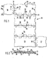
- FIG. 1 to 5 there is shown a container 10 comprising four like side panels 12 to 15, and two like end panels 1, 17 o
- Each panel 12 to 15 is similar so only a pair of adjacent panels 12, 13 will be described.
- Each panel 12, 13 is generally rectangular panel but the centre portion of each side edge of panel 12 has a recess 20 with two shorter sides 21 at right angles to the edge of the panel and a longer side 22 which is parallel therewith.
- the two portions 23 on either side of the recess 20 may also be regarded as projections as will be explained below.
- the side panel 13 is also essentially rectangular but its side edge adjacent to the panel 12 is formed with a central projection 24 of a shape generally complementary to the recess 20 in the panel 13.
- the projection 24 need not be an exact fit in the recess 20; instead, in a non-illuatrated embodiment, it may be a loose fit therein. That is to say, while in the drawings the depth and width of the recess 20 closely match the height and the width of the projection 24, this need not be sOe On either side of the projection 24 along the same edge there are two recesses 25 complementary to and co-operable with the opposite portions 23 of the panel 12.
- end panels 16 and 17 being generally similar to each other, only panel 16 will be described in detail. It, too, is a generally rectangular panel having on its side edge facing the panel 12 a central projection 24a flanked on either side by (recess) portions 25a which in general terms correspond with projection 24 and portions 25 of the side panel 12, respectively.
- the panels 12 to 17 may be made of any suitable materials e.g. paper or wood board, chipboard, laminated wood etc.
- the panels 12 to 17 are permanently connected together by a plurality of flexible straps 30 of predetermined length made of any suitable material, e.g. a polyethylene, nylon, paper or aluminium.
- Each pair of contiguous panels is secured together by three such straps 30.
- each strap 30 secured to the inner surface (the surface seen in Figure 1) of one panel passes through the gap 31 between the two panels and its other end is secured to the outer (unseen) surface of the adjacent panel, and vice versa.
- one strap 30a connects the inner surface of the recess 20 of panel 12 to the outer surface of the projection 24 of panel 13, passing through the gap 31.
- a respective strap 30b connects the internal surface of the recess 25 of the panel 13 to the outer surface of the projection 23 of the panel 12.
- the number and width of the straps may vary.
- the length of the straps 30 is such that in the fully collapsed position each panel lies wholly outside the contour of the adjacent panel.
- a band (not shown) may be passed around the outer surface of the panel 12, namely the unseen surface in the Figure 1, around its edge, down its internal surface, namely the surface seen in Figure 1, through the gap between the side surface of the projection 24 and the vertical edge of the recess 20, under the bottom surface of the panel 13, i.e. the unseen surface in Figure 1, up through the gap between the vertical edge of the recess 20 and the side surface of the projection 24 of the panel 14, continuing along the vertical side surface of the panel 14, along its upper edge and down along its outer surface, i o eo the surface not seen in Figure 1.
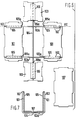
- the second embodiment of container according to the invention has two side panels 101 which are identical and are generally rectangular but formed with projections and recesses around their peripheries as shown.
- the two side panels 101 are interconnected by two loops 102 of flexible, almost non-extensible, flat plastics tape the ends of which are heat sealed to form the continuous loops 102 which encircle both side panels. That is to say, each loop 102 passes over the surface of each side panel 101, the portion 102a of each loop 102 shown spanning the side panels 101 being the upper layer of two superimposed layers of the loop 102.
- the container also has two identical end panels 103 which are substantially square but formed with projections and recesses around their peripheries as shown.
- the two end panels 103 are interconnected by a further endless loop 104 of the plastics tape, this further loop 104 being similar to but longer than each of the loops 102.
- each side panel 101 On one side of each side panel 101 (the side visible in Figure 6) are attached two strips 105 of card or board, each loop 102 passing between the corresponding strip 105 and the side panel 101 in order to locate the loop 102 which, however, can be pulled lengthwise between the strips l05 and the side panel 101.
- a similar strip 106 is attached to each end panel 103.
- the loops 102 and 104 are of a leng such that when the side and end panels 101, 103 are aid flat with the loops 102 and 104 taut (as shown in Figure 6) the side panels 101 and the end panels 103 are spaced apart to an extent enabling the base panel 107 (shown in the lower right-hand part of Figure 6) to be fitted between the side and end panels 101 and 103.
- the base panel 107 is also rectangular in general shape but is formed with projections and recesses which fit the recesses and projections respectively along the adjacent edges of the side and end panels 101 and 103,
- the two end panels 103 are laid flat with the loop 104 taut and the two side panels 101 are laid flat with the loops 102 taut and across the loop 104.
- the base panel 107 is then placed on top of the loops 102 and 104.
- the two aide panels 101 and the two end panels 103 are then swung upwardly around their lower edges, the edges of the projections on the base panel 1 07 optionally being chamfered to facilitate this movement.
- the projections and recesses on the panels 101, 103 and 107 come into abutting engagement and therefore guide the pivotal movement of each side and end panel 101, 103 by defining the axis of pivotal movement.
- the edges 105a, 106a of the strips 105, 106 assist in this guidance because they are set back from the outer edges of the projections by a dimension corresponding to the thickness of the base panel 107.
- Figure 7 shows a sectional view, taken on the location VII-VII in Figure 6, but after the side panels 101 and end panels 103 have been swung upwardly to their vertical positions so as to form an open-topped container.
- Figure 7 illustrates the loops 102 as being slack so that they show: it will be appreciated that the loops 102 are in fact tensioned and act to hold the side panels 101 in firm engagement with the base panel.
- the projections and recesses on the side and end panels interengage and these panels may be held in position by stapling, adhesive or by an encircling band.
- a lid may be provided if desired.
- Each side panel 101 is a rectangular board without projections or recesses.
- the edge 105a of each strip being set back from the adjacent edge of the side panel 101 by a dimension equal to the thickness of the base panel 107 which is plain rectangular board.
- An endless loop 102 of the plastics tape encircles both panels 101, passing between each strip 105 and the corresponding panel 101.
- the two end panels 103 are provided with respective strips 106 and are interconnected by an endless loop 104 of the plastics tape, the loop 104 passing between each strip 106 and the corresponding panel 103.
- the edge 106a of each strip is again set back from the adjacent edge of the end panel 103 by the thickness of the base panel 107.
- Figure 9 (which is a sectional view taken at location IX-IX in Figure 8) shows the panels 101 after they have been swung to their vertical positions in which they are held in tight engagement with the base panel 107 by the taut loops which are again shown slack so that they appear in the drawing.
- each strip 105 and 106 may be replaced by a plurality of shorter strips or by a strip of the form shown at 105 or 106 in Figure 6.
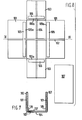
- Figure 10 shows the panels of the fourth embodiment of containero
- the container again has two side panels 101, two end panels 103 and a base panel 107, but in this embodiment the base panel 107 is permanently connected to the panels 101 and 103 instead of being separable therefrom, as in the containers of Figures 6 and 8 .
- Figure 10 shows an underside plan view of the panels 101, 103 and 107, i.e. shows the sides of the panels 101, 103 and 107 which would be laid upon a flat surface during erection of the container.
- the endless loops 102 and 104 do not completely encircle the side panels 101 and end panels 103, respectively.
- each side panel 101 is formed with three spaced slits 108 through which the loops 102 pass.
- each end panel 103 is formed with two slits 109 through which the loops 104 pass.
- the panels 101 and l03 are further cut or slit from their adjacent edges, each of these further cuts or slits running from the adjacent panel edge to the slit 108 or 109.
- loops 102 and 104 pass across the under side of the base panel 107, they are retained by three elongate strips 110 of card or board the longer edges of which stapled or otherwise secured to the underside of the panel 107, to hold the base panel l07 captive with respect to the loops 102 and 104 but enabling the loops 102 and 104 to be slid longitudinally between the strips 110 and the base panel 107.
- This helps to avoid the loops 102 and 104 becoming snagged and provides a means of locating one erected container upon another when the containers are stacked.
- This location for stacking is achieved by attaching strips 112 to the upper surface of the lid panel 113 in a configuration such that the strips 112 on the upper surface of the lid panel 113 nest within spaces left between the strips 110 on the underside of the base panel 107.
- the edges of the panels 101, 103 and 113 are formed with the projections and recesses shown, these interengaging in the erected container.
- the container of Figure 10 also includes a wedge 114 which is conveniently cut from the same sheet material as the panels 101, 103, 107 and 113.
- the wedge 114 is generally rectangular but has an angled edge 115 imparting the tapering profile shown.
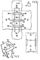
- the wedge 114 is used to tighten an endless loop 116 (Figure 11) of the plastics tape around the erected side panels and end panels 101 and 103 in order to hold these panels in their vertical positions, as illustrated by the fragmentary view of Figure ll o
- the endless loop 116 is passed around the erected panels 101 and 103 and a portion 117 of the loop 116 is inserted, through a slot 118 in one end panel 103, into the interior of the partially erected container.
- the wedge 114 is then pushed downwardly, with the smaller end of its tapering profile leading, into the loop portion l17, extending into the interior of the container. As the wedge 114 is pushed downwardly, it draws more of the loop 116 through the slot 118 and thereby progressively tightens the loop 116 around the panels 101 and 103. This progressive wedging action provides a very effective way of tightening the loop 116 manually, without the need for a banding machine.
- the wedge 114 may be left to project perpendicularly from the end panel 103, or may be swung to lie against the interior surface of the panel 103, this having the effect of applying a further slight tensioning to the loop 116.
- the wedge 114 may be secured against the end panel 103 by adhesive tape or a staple, or the contents of the container can be used to hold the wedge 114 against the interior surface of the end panel 103 o
- the wedge 114 can be simply withdrawn to loosen the loop 116 and enable the container to be collapsed.
- the width of the slot 118 is substantially equal to the thickness of the wedge 114 plus twice the thickness of a single run of the loop 116, so that the latter can be drawn smoothly through the slot 118 during wedging and so that the wedge 114 is adequately supported on its side faces by the loop portion 117 passing thereacross.
- the height of the slot 118 is considerably less than the height of the wedge 114, the latter being urged against the interior surface of the end panel 103 both above and below the slot 118 when the loop 116 is tightened.
- a strip similar to the strip 105 of Figure 8 is attached to the opposite surface of each panel 101 from that visible in Figure 10, and a strip similar to the strip 106 of Figure 8 is attached to the opposite surface of each panel l03 from that visible in Figure 10.
- Figures 6 to 11 can be repeatedly erected and collapsed without weakening of the hinges formed by the loops 102 and 104, can be collapsed to a flat, compact condition for transport or storage and can if desired by erected with the intended contents supported on the base panel 107.
- Figures 12 and 13 are diagrammatic sectional views of a container having opposite side panels 101 and a base panel 107 interconnected by a strap 120 formed from paper, plastics or other flexible material with two pockets 122 respectively accommodating the two side panels 101.
- the two thicknesses of the material of the strap 120 are preferably secured together over the length of the strap spanning the pockets 122.
- the strap 120 may have a substantial dimension in the direction perpendicular to the plane of Figures 12 and 13, and the term strap is to be construed broadly as including such a configuration.
- the internal surfaces of the pockets 122 may be coated with adhesive, e.g. a water-soluble an- hesive enabling wetted side panels 101 to be inserted into the pockets 122 and retained therein by the adhesive.
- FIG 12 shows the side panels 101, in their pre-shaped pockets 122, being swung towards their vertical positions illustrated in Figure 13. End panels (not shown) of the container are interconnected by a strap similar to strap 120.
- Figure 14 shows a shaped metal strip 124 which can be used to assist assembly and final rigidity of a side panel 101 and base 107 of a container.
- the strip 124 has a vertical limb 125 forming an abutment for the vertical side panel 101 and a horizontal limb 126 forming the base of a recess accommodating the edge of the base panel 107.
- the horizontal ledge of the strip 124 adjoining the limb 125 serves to locate the lower edgf of the panel.101. Since a plurality of such strips 124 (placed between the straps) locates the panels 101, 103 and 107, the panel edges need dot be provided with recesses or projections nor provided with the strips such as shown at 105 and 106 in Figure 8.
Landscapes
- Engineering & Computer Science (AREA)
- Mechanical Engineering (AREA)
- Life Sciences & Earth Sciences (AREA)
- Wood Science & Technology (AREA)
- Packages (AREA)
- Rigid Containers With Two Or More Constituent Elements (AREA)
Priority Applications (1)
| Application Number | Priority Date | Filing Date | Title |
|---|---|---|---|
| AT81303213T ATE13034T1 (de) | 1980-07-25 | 1981-07-13 | Zusammenklappbarer und aufrichtbarer behaelter. |
Applications Claiming Priority (4)
| Application Number | Priority Date | Filing Date | Title |
|---|---|---|---|
| GB8024470 | 1980-07-25 | ||
| GB8024470 | 1980-07-25 | ||
| GB8033791 | 1980-10-20 | ||
| GB8033791 | 1980-10-20 |
Publications (2)
| Publication Number | Publication Date |
|---|---|
| EP0045152A1 true EP0045152A1 (fr) | 1982-02-03 |
| EP0045152B1 EP0045152B1 (fr) | 1985-05-02 |
Family
ID=26276340
Family Applications (1)
| Application Number | Title | Priority Date | Filing Date |
|---|---|---|---|
| EP19810303213 Expired EP0045152B1 (fr) | 1980-07-25 | 1981-07-13 | Conteneur pliable et érigible |
Country Status (4)
| Country | Link |
|---|---|
| EP (1) | EP0045152B1 (fr) |
| DE (1) | DE3170273D1 (fr) |
| DK (1) | DK332781A (fr) |
| GR (1) | GR74294B (fr) |
Cited By (4)
| Publication number | Priority date | Publication date | Assignee | Title |
|---|---|---|---|---|
| WO1994010049A1 (fr) * | 1992-10-28 | 1994-05-11 | Mauser-Werke Gmbh | Bac de transport reutilisable |
| EP0639506A1 (fr) * | 1993-08-06 | 1995-02-22 | MAUSER-WERKE GmbH | Récipient de transport |
| US5454536A (en) * | 1994-01-13 | 1995-10-03 | Westinghouse Electric Corporation | Chair base assembly |
| GB2323588A (en) * | 1997-03-22 | 1998-09-30 | Impaq Limited | Collapsible structure with interlocking faces and securing means |
Citations (2)
| Publication number | Priority date | Publication date | Assignee | Title |
|---|---|---|---|---|
| AT29746B (de) * | 1905-08-02 | 1907-09-10 | Jakob Debeljak | Zusammenlegbare Behälter. |
| AT165425B (de) * | 1948-09-11 | 1950-02-25 | Kreuzbandgelenk für klappbare Kisten und Steigen |
-
1981
- 1981-07-13 DE DE8181303213T patent/DE3170273D1/de not_active Expired
- 1981-07-13 EP EP19810303213 patent/EP0045152B1/fr not_active Expired
- 1981-07-24 DK DK332781A patent/DK332781A/da not_active Application Discontinuation
- 1981-07-24 GR GR65620A patent/GR74294B/el unknown
Patent Citations (2)
| Publication number | Priority date | Publication date | Assignee | Title |
|---|---|---|---|---|
| AT29746B (de) * | 1905-08-02 | 1907-09-10 | Jakob Debeljak | Zusammenlegbare Behälter. |
| AT165425B (de) * | 1948-09-11 | 1950-02-25 | Kreuzbandgelenk für klappbare Kisten und Steigen |
Cited By (4)
| Publication number | Priority date | Publication date | Assignee | Title |
|---|---|---|---|---|
| WO1994010049A1 (fr) * | 1992-10-28 | 1994-05-11 | Mauser-Werke Gmbh | Bac de transport reutilisable |
| EP0639506A1 (fr) * | 1993-08-06 | 1995-02-22 | MAUSER-WERKE GmbH | Récipient de transport |
| US5454536A (en) * | 1994-01-13 | 1995-10-03 | Westinghouse Electric Corporation | Chair base assembly |
| GB2323588A (en) * | 1997-03-22 | 1998-09-30 | Impaq Limited | Collapsible structure with interlocking faces and securing means |
Also Published As
| Publication number | Publication date |
|---|---|
| DK332781A (da) | 1982-01-26 |
| GR74294B (fr) | 1984-06-21 |
| EP0045152B1 (fr) | 1985-05-02 |
| DE3170273D1 (en) | 1985-06-05 |
Similar Documents
| Publication | Publication Date | Title |
|---|---|---|
| US4089417A (en) | Flap lock bulk bin | |
| US4341338A (en) | Corrugated box bulk materials | |
| US4266670A (en) | Collapsible reinforced container | |
| US6749107B2 (en) | Container with improved stacking strength and resistance to lateral distortion | |
| US5897084A (en) | Folding trash bag expanding form and holder | |
| US5524815A (en) | Plural-compartment display carton with locking bottom and center support | |
| US4981254A (en) | Top structure for a collapsible carton | |
| CN111278739A (zh) | 储存和运输箱 | |
| US4119205A (en) | Palletized containers | |
| US4347967A (en) | Multicompartment folding carton | |
| US4214695A (en) | One-piece reinforced container | |
| US3268147A (en) | Crates for the carriage and storage of various goods | |
| US5042684A (en) | Bag-less box for flowable materials | |
| US4595137A (en) | Reinforcing element for collapsible container | |
| EP0045152A1 (fr) | Conteneur pliable et érigible | |
| US4192445A (en) | Packaging container including integral corner locks | |
| US2549509A (en) | Knockdown shipping container | |
| US6651873B2 (en) | Container with bag cuff grab means | |
| US4027818A (en) | Self locking container | |
| JPH0940023A (ja) | 紙製防水箱 | |
| US4275828A (en) | Dispensing box construction | |
| US5139194A (en) | Reusable self-locking carton and tray assembly | |
| GB2205083A (en) | Boxes formed from blanks | |
| EP0216763A1 (fr) | Conteneur pliable et procede de redressage. | |
| EP0647565A1 (fr) | Emballage pour un contenu substantiellement rectangulaire constitué d'un ou plusieurs articles |
Legal Events
| Date | Code | Title | Description |
|---|---|---|---|
| PUAI | Public reference made under article 153(3) epc to a published international application that has entered the european phase |
Free format text: ORIGINAL CODE: 0009012 |
|
| 17P | Request for examination filed |
Effective date: 19810804 |
|
| AK | Designated contracting states |
Designated state(s): AT BE CH DE FR GB IT LU NL SE |
|
| GRAA | (expected) grant |
Free format text: ORIGINAL CODE: 0009210 |
|
| AK | Designated contracting states |
Designated state(s): AT BE CH DE FR GB IT LI LU NL SE |
|
| PG25 | Lapsed in a contracting state [announced via postgrant information from national office to epo] |
Ref country code: NL Effective date: 19850502 Ref country code: LI Effective date: 19850502 Ref country code: IT Free format text: LAPSE BECAUSE OF FAILURE TO SUBMIT A TRANSLATION OF THE DESCRIPTION OR TO PAY THE FEE WITHIN THE PRESCRIBED TIME-LIMIT;WARNING: LAPSES OF ITALIAN PATENTS WITH EFFECTIVE DATE BEFORE 2007 MAY HAVE OCCURRED AT ANY TIME BEFORE 2007. THE CORRECT EFFECTIVE DATE MAY BE DIFFERENT FROM THE ONE RECORDED. Effective date: 19850502 Ref country code: FR Free format text: THE PATENT HAS BEEN ANNULLED BY A DECISION OF A NATIONAL AUTHORITY Effective date: 19850502 Ref country code: CH Effective date: 19850502 Ref country code: BE Effective date: 19850502 Ref country code: AT Effective date: 19850502 |
|
| REF | Corresponds to: |
Ref document number: 13034 Country of ref document: AT Date of ref document: 19850515 Kind code of ref document: T |
|
| PG25 | Lapsed in a contracting state [announced via postgrant information from national office to epo] |
Ref country code: SE Effective date: 19850530 |
|
| REF | Corresponds to: |
Ref document number: 3170273 Country of ref document: DE Date of ref document: 19850605 |
|
| PG25 | Lapsed in a contracting state [announced via postgrant information from national office to epo] |
Ref country code: LU Free format text: LAPSE BECAUSE OF NON-PAYMENT OF DUE FEES Effective date: 19850731 |
|
| REG | Reference to a national code |
Ref country code: CH Ref legal event code: PL |
|
| NLV1 | Nl: lapsed or annulled due to failure to fulfill the requirements of art. 29p and 29m of the patents act | ||
| EN | Fr: translation not filed | ||
| PLBE | No opposition filed within time limit |
Free format text: ORIGINAL CODE: 0009261 |
|
| STAA | Information on the status of an ep patent application or granted ep patent |
Free format text: STATUS: NO OPPOSITION FILED WITHIN TIME LIMIT |
|
| PG25 | Lapsed in a contracting state [announced via postgrant information from national office to epo] |
Ref country code: DE Effective date: 19860402 |
|
| 26N | No opposition filed | ||
| GBPC | Gb: european patent ceased through non-payment of renewal fee | ||
| PG25 | Lapsed in a contracting state [announced via postgrant information from national office to epo] |
Ref country code: GB Effective date: 19881118 |