EP0045341B1 - Verlängerbare Aufhängevorrichtung - Google Patents
Verlängerbare Aufhängevorrichtung Download PDFInfo
- Publication number
- EP0045341B1 EP0045341B1 EP80870037A EP80870037A EP0045341B1 EP 0045341 B1 EP0045341 B1 EP 0045341B1 EP 80870037 A EP80870037 A EP 80870037A EP 80870037 A EP80870037 A EP 80870037A EP 0045341 B1 EP0045341 B1 EP 0045341B1
- Authority
- EP
- European Patent Office
- Prior art keywords
- fact
- collar
- suspending device
- hole
- zone
- Prior art date
- Legal status (The legal status is an assumption and is not a legal conclusion. Google has not performed a legal analysis and makes no representation as to the accuracy of the status listed.)
- Expired
Links
- 230000037431 insertion Effects 0.000 claims abstract description 6
- 238000003780 insertion Methods 0.000 claims abstract description 6
- 230000035515 penetration Effects 0.000 claims abstract description 5
- 238000005192 partition Methods 0.000 claims abstract 2
- 230000006835 compression Effects 0.000 claims 1
- 238000007906 compression Methods 0.000 claims 1
- 230000000295 complement effect Effects 0.000 description 10
- 240000008042 Zea mays Species 0.000 description 2
- 229910000831 Steel Inorganic materials 0.000 description 1
- 238000006073 displacement reaction Methods 0.000 description 1
- 230000000694 effects Effects 0.000 description 1
- 239000000463 material Substances 0.000 description 1
- 239000010959 steel Substances 0.000 description 1
Images

Classifications
-
- F—MECHANICAL ENGINEERING; LIGHTING; HEATING; WEAPONS; BLASTING
- F24—HEATING; RANGES; VENTILATING
- F24D—DOMESTIC- OR SPACE-HEATING SYSTEMS, e.g. CENTRAL HEATING SYSTEMS; DOMESTIC HOT-WATER SUPPLY SYSTEMS; ELEMENTS OR COMPONENTS THEREFOR
- F24D19/00—Details
- F24D19/02—Arrangement of mountings or supports for radiators
- F24D19/024—Functioning details of supporting means for radiators
- F24D19/0243—Means for moving the radiator horizontally to adjust the radiator position
-
- F—MECHANICAL ENGINEERING; LIGHTING; HEATING; WEAPONS; BLASTING
- F16—ENGINEERING ELEMENTS AND UNITS; GENERAL MEASURES FOR PRODUCING AND MAINTAINING EFFECTIVE FUNCTIONING OF MACHINES OR INSTALLATIONS; THERMAL INSULATION IN GENERAL
- F16B—DEVICES FOR FASTENING OR SECURING CONSTRUCTIONAL ELEMENTS OR MACHINE PARTS TOGETHER, e.g. NAILS, BOLTS, CIRCLIPS, CLAMPS, CLIPS OR WEDGES; JOINTS OR JOINTING
- F16B13/00—Dowels or other devices fastened in walls or the like by inserting them in holes made therein for that purpose
- F16B13/12—Separate metal or non-separate or non-metal dowel sleeves fastened by inserting the screw, nail or the like
-
- F—MECHANICAL ENGINEERING; LIGHTING; HEATING; WEAPONS; BLASTING
- F24—HEATING; RANGES; VENTILATING
- F24D—DOMESTIC- OR SPACE-HEATING SYSTEMS, e.g. CENTRAL HEATING SYSTEMS; DOMESTIC HOT-WATER SUPPLY SYSTEMS; ELEMENTS OR COMPONENTS THEREFOR
- F24D19/00—Details
- F24D19/02—Arrangement of mountings or supports for radiators
-
- F—MECHANICAL ENGINEERING; LIGHTING; HEATING; WEAPONS; BLASTING
- F24—HEATING; RANGES; VENTILATING
- F24D—DOMESTIC- OR SPACE-HEATING SYSTEMS, e.g. CENTRAL HEATING SYSTEMS; DOMESTIC HOT-WATER SUPPLY SYSTEMS; ELEMENTS OR COMPONENTS THEREFOR
- F24D19/00—Details
- F24D19/02—Arrangement of mountings or supports for radiators
- F24D19/0203—Types of supporting means
- F24D19/0206—Tube shaped supports inserted into a wall
-
- F—MECHANICAL ENGINEERING; LIGHTING; HEATING; WEAPONS; BLASTING
- F16—ENGINEERING ELEMENTS AND UNITS; GENERAL MEASURES FOR PRODUCING AND MAINTAINING EFFECTIVE FUNCTIONING OF MACHINES OR INSTALLATIONS; THERMAL INSULATION IN GENERAL
- F16B—DEVICES FOR FASTENING OR SECURING CONSTRUCTIONAL ELEMENTS OR MACHINE PARTS TOGETHER, e.g. NAILS, BOLTS, CIRCLIPS, CLAMPS, CLIPS OR WEDGES; JOINTS OR JOINTING
- F16B13/00—Dowels or other devices fastened in walls or the like by inserting them in holes made therein for that purpose
- F16B13/12—Separate metal or non-separate or non-metal dowel sleeves fastened by inserting the screw, nail or the like
- F16B13/126—Separate metal or non-separate or non-metal dowel sleeves fastened by inserting the screw, nail or the like fastened by inserting an unthreaded element, e.g. pin or nail
Definitions
- the present invention relates to a hanging device to be placed in a wall or other walls which, in its most elaborate form, is intended to be used as a console support more particularly for radiator elements and / or pipes and cables.
- hooking devices generally constituted by a strip folded in tubular form split over its entire length, so as to have a certain elasticity and comprising - produced by stamping - a number of roughness, holes and other cuts.
- This type of device was then improved by the holder in order to further improve the holding of the hanging device in the wall, and this as described, for example in Belgian patent No 875916, by providing a means of additional expansion. That one brings into an area of the incoming part of the device, internally narrowed area, brought into an inner circle of diameter smaller than the normal inner diameter of the incoming part of the device, at certain points or lines, forming bosses, so that the points or lines, bosses adjoining the first, will open outward, that is to say they will be brought out of an outer circle of diameter greater than the incoming part of the device, and this under the effect of this complementary means of expansion.
- the present invention overcomes certain drawbacks of the devices described above and, more particularly, by further improving the behavior of the attachment device in the wall or other walls; in addition, it ensures the positioning of the device by preventing displacement from occurring when the complementary expansion means are brought back to the zone of narrowed points or lines.
- the device is provided at its external part (not entering) with a means, an optional extension or diameter adapter.
- the attachment device to be placed in a wall or other walls, of tubular shape with variable diameter along its length, split and of constant thickness over its entire length, having on the internal side of its incoming part a zone of lines of bosses, capable of being forced outwards by a complementary means of radial expansion brought by depression into this zone after the placement of the hooking device in the hole, is characterized in that the complementary means of expansion is of a length at most equal to the length of the area of boss lines 2, 3, and in that it comprises a part of diameter substantially larger than that of the incoming part, situated beyond its incoming part, towards the outside, part formed by a flaring towards the outside, straight inclined or rounded, forming with the incoming part at a non-zero angle less than or equal to 90 °, part of diameter substantially larger than that of the part entering, forming a stop when the device is inserted into the hole, a device whose external part to the wall is itself fitted out as a support or is capable of receiving a support device.
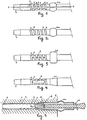
- hooking devices of generally tubular shape, all having a longitudinal slot (fig. 1) in the entering part, a zone of bosses, inlays with stamping of high parts 2 and of lower parts 3, adjoining, which, as shown, are the imprint of a screw thread, with high lines 2 and low 3, devices provided at the outward end of their incoming part with a limiting stop sinking: either 4a a rounded outer blister, or 4b an outer blister with a straight pan, or 4c an outward flare, which will cause a larger diameter of the device after the stop.
- the inward end of the device has an inwardly tapered flare 5, facilitating the introduction of the device into the hole in the wall 6.
- the area of the bosses 2,3 can , to increase its flexibility and facilitate its exit to the outside of the upper parts 2, be provided with cutouts, holes 7, placed on the lower lines 3 fig. 3, or one can provide one (or more) longitudinal window (s) 8 (fig. 4).
- the complementary expansion means 9 will not be brought into the zone of the bosses 2, 3 until after the device itself has been placed in the hole in the wall 6.
- the stops 4a, b, c being more particularly intended to avoid that, when one proceeds to the establishment of the complementary expansion means 9, there is an additional depression of the device itself in the hole of the wall 6.
- a device having a flare 11 towards the outside which is not located at the end of the incoming part of the device, but before the latter; this arrangement is particularly useful for the perfect holding of the device in the hole of a wall 6 and for there to be perfect contact over the entire length of the incoming part of the device and the wall of the hole, while the latter generally has a larger diameter, the further one moves away from its bottom and particularly at its exit.
- the device is provided at the outward end of its incoming part with a means of limiting its penetration into the wall, means which have been shown of the blister type towards the outside, rounded 4a (fig. 5 and 6) with right pan 4b (fig. 8).
- extension 12 which, depending on whether it is placed in (fig. 6) or on (fig. 8) the device, is of a diameter less than or greater than the diameter of the part remaining outside the device, extension 12 which therefore possibly serves as a diameter adapter.
- This extension 12 acts as a support and is, for example, as shown, provided with a slot 13 in which can rest and / or be held the end of a radiator element (not shown).
- a clamping ring (FIGS. 6 and 7), a collar 14 of annular shape or, again, in FIGS. 8 and 9, a round collar 15 except for an outward bulge 16; in one as in the other case, the collar 14,15 is provided with a hole 17 arranged in thread 16; as shown, a clamping screw 18 is provided; however, in the case of a collar 15 with bulge 16, it is possible to obtain tightening by deformation of the collar 15 by means of an L-shaped tool (not shown), the short branch of which is introduced into the hole 17 of the collar 15; by sufficiently serious pressure on the other branch, the collar 15 is deformed.
- a passage hole can be provided, either on the device itself, or on the extension, so that the screw 18 bears directly or on the extension 12 or on the device itself.
- the collar 14,15 is not positioned in advance, neither with respect to the device, nor, more particularly, with respect to the extension 12, which would be the case if a passage hole for the screw 18; one can indeed, in the opposite case, move forward or backward without any constraint the extension 12 in or on the device.
- This additional expansion means 9 may include in its center a straight threaded pipe making it possible to remove this additional means by screwing.
Landscapes
- Engineering & Computer Science (AREA)
- General Engineering & Computer Science (AREA)
- Mechanical Engineering (AREA)
- Chemical & Material Sciences (AREA)
- Thermal Sciences (AREA)
- Combustion & Propulsion (AREA)
- Physics & Mathematics (AREA)
- Dowels (AREA)
- Holders For Apparel And Elements Relating To Apparel (AREA)
- Clamps And Clips (AREA)
- Tents Or Canopies (AREA)
- Massaging Devices (AREA)
- Spinning Or Twisting Of Yarns (AREA)
Claims (9)
Priority Applications (3)
| Application Number | Priority Date | Filing Date | Title |
|---|---|---|---|
| AT80870037T ATE7419T1 (de) | 1980-07-31 | 1980-07-31 | Verlaengerbare aufhaengevorrichtung. |
| DE8080870037T DE3067754D1 (en) | 1980-07-31 | 1980-07-31 | Extendable suspending device |
| EP80870037A EP0045341B1 (de) | 1980-07-31 | 1980-07-31 | Verlängerbare Aufhängevorrichtung |
Applications Claiming Priority (1)
| Application Number | Priority Date | Filing Date | Title |
|---|---|---|---|
| EP80870037A EP0045341B1 (de) | 1980-07-31 | 1980-07-31 | Verlängerbare Aufhängevorrichtung |
Publications (2)
| Publication Number | Publication Date |
|---|---|
| EP0045341A1 EP0045341A1 (de) | 1982-02-10 |
| EP0045341B1 true EP0045341B1 (de) | 1984-05-09 |
Family
ID=8187494
Family Applications (1)
| Application Number | Title | Priority Date | Filing Date |
|---|---|---|---|
| EP80870037A Expired EP0045341B1 (de) | 1980-07-31 | 1980-07-31 | Verlängerbare Aufhängevorrichtung |
Country Status (3)
| Country | Link |
|---|---|
| EP (1) | EP0045341B1 (de) |
| AT (1) | ATE7419T1 (de) |
| DE (1) | DE3067754D1 (de) |
Families Citing this family (3)
| Publication number | Priority date | Publication date | Assignee | Title |
|---|---|---|---|---|
| DE3308217A1 (de) * | 1983-03-08 | 1984-09-13 | Helmut 7778 Markdorf Mayer | Wandhalterung zum befestigen von heizkoerpern od. dgl. |
| GB2153472A (en) * | 1983-08-06 | 1985-08-21 | Edward Victor Byers | Fastening device |
| GB8615351D0 (en) * | 1986-06-24 | 1986-07-30 | Tackburn Ltd | Fixing device |
Citations (1)
| Publication number | Priority date | Publication date | Assignee | Title |
|---|---|---|---|---|
| BE875916A (fr) * | 1979-04-27 | 1979-08-16 | Gregorovic Dragutin | Dispositif d'accrochage a incrustations laterales |
Family Cites Families (9)
| Publication number | Priority date | Publication date | Assignee | Title |
|---|---|---|---|---|
| DE7702415U1 (de) * | Fa. Hans Gerd Gottbehuet, 5620 Velbert | |||
| DE6812064U (de) * | 1968-12-18 | 1969-05-29 | Hans Zimmermann | Justierbare heizkoerperkonsole |
| DE1815820B1 (de) * | 1968-12-19 | 1970-07-30 | Hans Zimmermann | Heizkoerperkonsole |
| DE1903589B1 (de) * | 1969-01-24 | 1970-12-23 | Hans Zimmermann | Heizkoerperkonsole |
| CH517922A (de) * | 1970-11-03 | 1972-01-15 | Konsolen Gmbh | Befestigungsvorrichtung für Heizelemente |
| DE2138246A1 (de) * | 1971-07-30 | 1973-02-08 | Schmoelz & Wilfer Kg | Anker |
| DE2163297A1 (de) * | 1971-12-20 | 1973-06-28 | Peter Trieb | Pete-duebel fuer hoehen-, seiten- und laengenverstellbare befestigungen |
| IT1073333B (it) * | 1976-10-08 | 1985-04-17 | Bassani Spa | Chiodo ad espansione, specialmente adatto per applicazione a pareti relativamente sottili |
| FR2416375A1 (fr) * | 1978-02-07 | 1979-08-31 | Prospection & Inventions | Perfectionnement aux chevilles a noyau d'expansion |
-
1980
- 1980-07-31 DE DE8080870037T patent/DE3067754D1/de not_active Expired
- 1980-07-31 AT AT80870037T patent/ATE7419T1/de not_active IP Right Cessation
- 1980-07-31 EP EP80870037A patent/EP0045341B1/de not_active Expired
Patent Citations (1)
| Publication number | Priority date | Publication date | Assignee | Title |
|---|---|---|---|---|
| BE875916A (fr) * | 1979-04-27 | 1979-08-16 | Gregorovic Dragutin | Dispositif d'accrochage a incrustations laterales |
Also Published As
| Publication number | Publication date |
|---|---|
| DE3067754D1 (en) | 1984-06-14 |
| ATE7419T1 (de) | 1984-05-15 |
| EP0045341A1 (de) | 1982-02-10 |
Similar Documents
| Publication | Publication Date | Title |
|---|---|---|
| EP1412107B1 (de) | Dehnungswerkzeug für aufweitzange | |
| FR2542396A1 (fr) | Ensemble de rivet borgne | |
| FR2532015A1 (fr) | Dispositif d'attache a ecrou d'ancrage | |
| FR2790046A1 (fr) | Dispositif de fixation de deux panneaux ou analogues forme de deux pieces cooperantes | |
| FR2509031A1 (fr) | Echangeur de chaleur comportant une pluralite d'elements tubulaires individuels et procede de fabrication d'un tel echangeur de chaleur | |
| FR2482189A1 (fr) | Raccord a enfichage destine a un faisceau de tuyaux hydrauliques devant etre relies ensemble, alimentant des machines et appareils dans une exploitation miniere au fond | |
| FR2465569A1 (fr) | Manche tubulaire rond pour outils domestiques | |
| FR2657925A1 (fr) | Dispositif de fixation sur panneau de type sandwich. | |
| FR2489902A1 (fr) | Element de liaison | |
| FR2831643A1 (fr) | Raccord instantane demontable pour au moins un tube | |
| CH666952A5 (fr) | Porte-lampe miniature. | |
| EP0045341A1 (de) | Verlängerbare Aufhängevorrichtung | |
| FR2728332A1 (fr) | Echangeur de chaleur, procede pour sa fabrication et outil pour la mise en oeuvre du procede | |
| EP0049645B1 (de) | T-Montage und Verfahren zur Herstellung | |
| EP0165370A1 (de) | Hängevorrichtung | |
| FR2474134A1 (fr) | Element de fixation pour au moins une conduite tubulaire, notamment pour la canalisation d'essence d'un vehicule automobile | |
| FR2623575A1 (fr) | Dispositif pour la fixation d'accessoires d'equipement domestique en forme de barres | |
| EP0543723A1 (de) | Röhrenförmige Dübelhülse mit einem Spreizkern | |
| FR2740125A1 (fr) | Embout perfectionne pour bobine de materiau d'essuyage | |
| FR2566848A1 (fr) | Dispositif pour la fixation d'une manchette sur une ouverture d'une paroi quelconque d'epaisseur variable | |
| CH675893A5 (en) | Post and socket assembly - has steel rods on bottom of post which pass through holes in wall of socket to penetrate ground | |
| FR2812901A1 (fr) | Noeuds d'assemblage pour echafaudage tubulaire permettant de relier un premier tube a au moins un second tube | |
| FR3023309A1 (fr) | Dispositif de raccordement et procede de montage d'un tel dispositif | |
| FR2936845A1 (fr) | Cage d'ecrou | |
| FR2574840A1 (fr) | Fermeture pour trous de passage de serre-joints |
Legal Events
| Date | Code | Title | Description |
|---|---|---|---|
| PUAI | Public reference made under article 153(3) epc to a published international application that has entered the european phase |
Free format text: ORIGINAL CODE: 0009012 |
|
| AK | Designated contracting states |
Designated state(s): AT BE CH DE FR GB IT LU NL |
|
| RAP1 | Party data changed (applicant data changed or rights of an application transferred) |
Owner name: GREGOROVIC, MATHILDE Owner name: KOEKKELKOREN, JOSEPHINE |
|
| 17P | Request for examination filed |
Effective date: 19820331 |
|
| ITF | It: translation for a ep patent filed | ||
| GRAA | (expected) grant |
Free format text: ORIGINAL CODE: 0009210 |
|
| AK | Designated contracting states |
Designated state(s): AT BE CH DE FR GB IT LI LU NL |
|
| REF | Corresponds to: |
Ref document number: 7419 Country of ref document: AT Date of ref document: 19840515 Kind code of ref document: T |
|
| REF | Corresponds to: |
Ref document number: 3067754 Country of ref document: DE Date of ref document: 19840614 |
|
| PGFP | Annual fee paid to national office [announced via postgrant information from national office to epo] |
Ref country code: CH Payment date: 19840620 Year of fee payment: 5 |
|
| PGFP | Annual fee paid to national office [announced via postgrant information from national office to epo] |
Ref country code: DE Payment date: 19840621 Year of fee payment: 5 |
|
| PGFP | Annual fee paid to national office [announced via postgrant information from national office to epo] |
Ref country code: BE Payment date: 19840630 Year of fee payment: 5 |
|
| PGFP | Annual fee paid to national office [announced via postgrant information from national office to epo] |
Ref country code: FR Payment date: 19840717 Year of fee payment: 5 |
|
| PGFP | Annual fee paid to national office [announced via postgrant information from national office to epo] |
Ref country code: AT Payment date: 19840720 Year of fee payment: 5 |
|
| PGFP | Annual fee paid to national office [announced via postgrant information from national office to epo] |
Ref country code: NL Payment date: 19840730 Year of fee payment: 5 |
|
| PG25 | Lapsed in a contracting state [announced via postgrant information from national office to epo] |
Ref country code: LU Free format text: LAPSE BECAUSE OF NON-PAYMENT OF DUE FEES Effective date: 19840731 |
|
| PLBE | No opposition filed within time limit |
Free format text: ORIGINAL CODE: 0009261 |
|
| STAA | Information on the status of an ep patent application or granted ep patent |
Free format text: STATUS: NO OPPOSITION FILED WITHIN TIME LIMIT |
|
| 26N | No opposition filed | ||
| PG25 | Lapsed in a contracting state [announced via postgrant information from national office to epo] |
Ref country code: AT Effective date: 19850731 |
|
| PG25 | Lapsed in a contracting state [announced via postgrant information from national office to epo] |
Ref country code: NL Effective date: 19860201 |
|
| GBPC | Gb: european patent ceased through non-payment of renewal fee | ||
| NLV4 | Nl: lapsed or anulled due to non-payment of the annual fee | ||
| PG25 | Lapsed in a contracting state [announced via postgrant information from national office to epo] |
Ref country code: LI Effective date: 19860731 Ref country code: CH Effective date: 19860731 Ref country code: BE Effective date: 19860731 |
|
| BERE | Be: lapsed |
Owner name: GREGOROVIC MATHILDE Effective date: 19860731 Owner name: KOEKKELTOREN JOSEPHINE Effective date: 19860731 |
|
| PG25 | Lapsed in a contracting state [announced via postgrant information from national office to epo] |
Ref country code: FR Free format text: LAPSE BECAUSE OF NON-PAYMENT OF DUE FEES Effective date: 19870331 |
|
| REG | Reference to a national code |
Ref country code: CH Ref legal event code: PL |
|
| PG25 | Lapsed in a contracting state [announced via postgrant information from national office to epo] |
Ref country code: DE Effective date: 19870401 |
|
| REG | Reference to a national code |
Ref country code: FR Ref legal event code: ST |
|
| PG25 | Lapsed in a contracting state [announced via postgrant information from national office to epo] |
Ref country code: GB Effective date: 19881118 |