EP0045470B1 - Procédé et dispositif de cintrage d'un élément métallique allongé - Google Patents
Procédé et dispositif de cintrage d'un élément métallique allongé Download PDFInfo
- Publication number
- EP0045470B1 EP0045470B1 EP81105933A EP81105933A EP0045470B1 EP 0045470 B1 EP0045470 B1 EP 0045470B1 EP 81105933 A EP81105933 A EP 81105933A EP 81105933 A EP81105933 A EP 81105933A EP 0045470 B1 EP0045470 B1 EP 0045470B1
- Authority
- EP
- European Patent Office
- Prior art keywords
- temperature
- heated zone
- sensors
- zone
- bending
- Prior art date
- Legal status (The legal status is an assumption and is not a legal conclusion. Google has not performed a legal analysis and makes no representation as to the accuracy of the status listed.)
- Expired
Links
- 238000005452 bending Methods 0.000 title claims description 18
- 238000000034 method Methods 0.000 title claims description 15
- 229910052751 metal Inorganic materials 0.000 title claims description 11
- 239000002184 metal Substances 0.000 title claims description 10
- 238000010438 heat treatment Methods 0.000 claims description 32
- 238000001514 detection method Methods 0.000 claims description 8
- 230000001154 acute effect Effects 0.000 claims description 4
- 230000003247 decreasing effect Effects 0.000 claims description 4
- 230000005855 radiation Effects 0.000 claims description 3
- 238000011144 upstream manufacturing Methods 0.000 claims description 3
- 230000006698 induction Effects 0.000 claims 1
- 238000007689 inspection Methods 0.000 claims 1
- 238000006073 displacement reaction Methods 0.000 description 4
- 238000004458 analytical method Methods 0.000 description 3
- 238000012937 correction Methods 0.000 description 3
- 238000001816 cooling Methods 0.000 description 2
- XLYOFNOQVPJJNP-UHFFFAOYSA-N water Substances O XLYOFNOQVPJJNP-UHFFFAOYSA-N 0.000 description 2
- 238000009529 body temperature measurement Methods 0.000 description 1
- 230000007547 defect Effects 0.000 description 1
- 238000002347 injection Methods 0.000 description 1
- 239000007924 injection Substances 0.000 description 1
- JEIPFZHSYJVQDO-UHFFFAOYSA-N iron(III) oxide Inorganic materials O=[Fe]O[Fe]=O JEIPFZHSYJVQDO-UHFFFAOYSA-N 0.000 description 1
- 238000012423 maintenance Methods 0.000 description 1
- 230000003287 optical effect Effects 0.000 description 1
- 239000013307 optical fiber Substances 0.000 description 1
- 230000000704 physical effect Effects 0.000 description 1
- 239000007921 spray Substances 0.000 description 1
- 238000010408 sweeping Methods 0.000 description 1
- 230000008685 targeting Effects 0.000 description 1
- 238000012360 testing method Methods 0.000 description 1
Images

Classifications
-
- B—PERFORMING OPERATIONS; TRANSPORTING
- B21—MECHANICAL METAL-WORKING WITHOUT ESSENTIALLY REMOVING MATERIAL; PUNCHING METAL
- B21D—WORKING OR PROCESSING OF SHEET METAL OR METAL TUBES, RODS OR PROFILES WITHOUT ESSENTIALLY REMOVING MATERIAL; PUNCHING METAL
- B21D7/00—Bending rods, profiles, or tubes
- B21D7/16—Auxiliary equipment, e.g. for heating or cooling of bends
- B21D7/162—Heating equipment
-
- B—PERFORMING OPERATIONS; TRANSPORTING
- B21—MECHANICAL METAL-WORKING WITHOUT ESSENTIALLY REMOVING MATERIAL; PUNCHING METAL
- B21D—WORKING OR PROCESSING OF SHEET METAL OR METAL TUBES, RODS OR PROFILES WITHOUT ESSENTIALLY REMOVING MATERIAL; PUNCHING METAL
- B21D7/00—Bending rods, profiles, or tubes
- B21D7/02—Bending rods, profiles, or tubes over a stationary forming member; by use of a swinging forming member or abutment
- B21D7/024—Bending rods, profiles, or tubes over a stationary forming member; by use of a swinging forming member or abutment by a swinging forming member
- B21D7/025—Bending rods, profiles, or tubes over a stationary forming member; by use of a swinging forming member or abutment by a swinging forming member and pulling or pushing the ends of the work
Definitions
- the present invention relates to a method of bending an elongated metal element of constant cross section by heating a narrow zone around the periphery of this element using a heating collar surrounding this zone, pushed on one end of the element and maintenance of its other end by a pivoting arm, in which the temperature of the zone heated by the periphery of the element is kept substantially constant by detecting the temperature of the latter, and by increasing or decreasing the heat input at one or other of the points of said periphery of the element depending on whether the temperature there is lower or higher, to a set value corresponding to a uniform temperature around the heated zone. It applies in particular to the bending of large diameter tubes, but also to that of bars, profiles, etc. It also extends to a device for the implementation of this process.
- the invention aims to remedy this drawback, and to provide a method and a device for bending an elongated metal element which ensures a constant temperature of the heated zone over its entire periphery as well as over time.
- the method of the invention is characterized in that the temperature of the heated zone is detected at at least two points around the periphery of the element, one of which is on the side of the center of curvature, and the other opposite in the first, using sensors, which are made to describe a back and forth movement parallel to the axis of the element not yet bent and sweeping the width of the heated area.
- the temperature of the heated area is detected by aiming it, on the one hand using a first set of sensors arranged upstream of the heated area and whose axis makes an acute angle with l axis of the element not yet bent, on the other hand using a second set of sensors spaced longitudinally from the first and of orientation such that it allows them to observe the part of the heated zone which can be obscured vis-à-vis the first set of sensors by the heating collar during part of the bending operation.
- the thermal input in the detection zones is increased or decreased by providing a heating collar with constant power corresponding to the minimum temperature of deformation of the heated zone of the elongated element, and by bringing it closer or away, or modifying it the power supplied to additional heating elements arranged opposite the detection zones.
- the invention also extends to a bending device for implementing the method defined above, comprising a heating collar surrounding the area to be heated to allow bending, means for pushing said element, and a pivoting arm for holding the other end of the element, detectors for the temperature of the heated zone, and means for increasing or decreasing the heat input at one or other of the points of the metallic element depending on whether the temperature there is higher or lower than a set value corresponding to a uniform temperature around the heated area, characterized in that the temperature sensors of the heated area are arranged at at least two points around the edge of the element, one of which is on the side of the center of the curvature, and the other on the opposite side, and in that it comprises means for alternating longitudinal displacement of the detectors enabling them to scan the width of the heated zone.
- It includes temperature detectors connected via a multiplexing device, on the one hand to separate temperature recorders, on the other hand to a peak storage detector and to a temperature display device. maximum, as well as preferably a successive display of temperatures on the same recorder.
- the detection means are connected to servomotors, on the one hand for the overall displacement of the heating collar, and on the other hand for deformation thereof.
- the heating collar consists of an internal collar providing constant power corresponding to the minimum deformation temperature of the heated zone, and of additional heating elements arranged opposite the detection zones, and it furthermore comprises means for bringing together or move them away from the elongated metal element, or to modify the power supplied to them.
- the bending tube 1 is subjected at one end by a mechanical device to a thrust represented by the arrow 2, while a movable arm 3, rotating around an axis 4, maintains the other end of the tube by a collar 5.
- a movable arm 3 rotating around an axis 4, maintains the other end of the tube by a collar 5.
- the heating of the zone where the deformation must occur, of an appropriate width, is ensured by an inductor collar 6, this being followed by a cooling device 7 to the air or water.
- Figure 2 shows a section through the axis of the tube to be bent. Its wall is represented at 10.
- the zone to be heated 11 is surrounded by the inductor 6.
- An infrared radiation sensor 12 is arranged upstream of the heated zone relative to the inductor and inclined so as to be able to target the entire heated area without interference from the inductor.
- a sensor is driven, by means not shown, with a back-and-forth movement represented by the double arrow 12A, so as to be able to record the temperature of the entire width of the heated zone, and in particular the maximum temperature .
- sensors are arranged at other points around the periphery of the tube, for example three other sensors at 90 ° from one another.
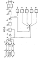
- FIG. 3 represents a temperature analysis chain using four sensors such as that of FIG. 2.
- Each of the sensors 12, 13, 14, 15 is connected by an optical fiber 16, 17, 18, 19, to an optical amplifier 20, 21, 22, 23.
- the four amplifiers are connected to a multiplexer 24, at terminals a, b, c, d, the multiplexing being controlled by a movable contact.
- the multiplexer is followed by an amplifier 26, followed by a peak detector-memorizer 27.
- the latter is connected by a linearization device 28 and an emissivity coefficient adjustment device 29, on the one hand to a digital display, on the other hand to a temperature recorder.
- the digital maximum temperature display panel 30 is connected to a member for displaying the maximum and minimum setpoints 31, itself connected to alarm indicators 32, 33.
- the recorder 34 successively records the four temperature readings on the same graph.
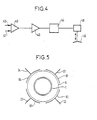
- a comparator 40 receives the indications, on the one hand from the temperature read by a sensor (arrow 41 on the other hand from the reference temperature (arrow 42), and delivers a signal giving in amplitude and in sign the value of their difference. This signal is transmitted to an amplifier 43, then to a servomotor control 44.
- the servomotor 45 exerts pressure or traction on an inductor with variable geometry 46. If the temperature read is lower than the temperature as a reference, it brings the inductor closer to the surface of the tube and, if it is higher, moves it away.
- the heated area of the tube 1 is surrounded by an inductor collar 6 of shape corresponding to the theoretical shape of the tube (circular). It is surrounded by four additional inductors 61, 62, 63, 64, 90 ° apart, and with the same axes as the temperature sensors.
- Inductor 6 is coaxial with the tube and supplied with a power such that each sensor reads the minimum deformation temperature. The temperature observed for each sensor is compared to the set temperature and the value of the difference commands an injection of electrical power into the corresponding additional inductor, or a displacement of the latter to vary its air gap.
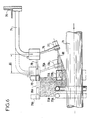
- the device of Figure 6 aims to remedy a difficulty resulting from the fact that, in the implementation of the method, it is necessary to move the heating collar back during the course of the operation, the heated area tending to move forward due to the progression of the metal element, the heating of which is not instantaneous.
- the temperature of the heated zone is detected by means of temperature sensors arranged so as to form an angle relative to the axis sufficiently acute to target the heated zone under the heating collar, it has been found to be following tests that the sensors could have in their field at the end of the operation only part of the heated area, the other part being obscured by the heating collar.
- the method corresponding to the device shown in this figure aims to remedy this drawback and to allow constant observation of the maximum temperature of the heated area around its entire periphery, and consequently an appropriate correction of the thermal inputs around the periphery of the element to be bent, and maximum reduction of defects in the shape of the bent metal element.
- the tube 71 is pushed in the direction of the arrow.
- the heating collar 72 is placed in the initial preheating period in position 72A, then it is moved back during the bending operation in position 72B.
- the water spray cooling toroid initially in position 73A, is moved back with the heating collar to position 73B.
- the infrared temperature detectors are carried by arms 74, fixed to a movable support 75.
- the arm 74 carries two gripping grippers for the detectors, the gripper 76 carrying the detector 77, with an aiming axis making an acute angle with the axis of advancement of the tube, and the detector 79, with an aiming axis perpendicular to this same line of advancement.
- the mobile support and the arm are moved back and forth with amplitude A L.
- the arm 76 and the detector 77 therefore advance to positions 76A and 77A, then return to their initial positions.
- the arm 78 and the detector 79 advance to positions 78A and 79A, then return to their initial positions.
- the scanning field by the detectors is shown in gray in the figure (80).
- the detector 77 scans substantially the entire heated area. When the heating collar has been moved back to position 72B, the heated area is partly obscured by the detector 77, but the rest of this area is in the field scanned by the detector 79.
- the asymmetry of thermal contribution to the heated zone could be detected by measuring other physical properties than infrared radiation.
Landscapes
- Engineering & Computer Science (AREA)
- Mechanical Engineering (AREA)
- Investigating Or Analyzing Materials Using Thermal Means (AREA)
- Bending Of Plates, Rods, And Pipes (AREA)
- Radiation Pyrometers (AREA)
Description
- La présente invention concerne un procédé de cintrage d'un élément métallique allongé de section droite constante par chauffage d'une zone étroite du pourtour de cet élément à l'aide d'un collier chauffant entourant cette zone, poussée sur une extrémité de l'élément et maintien de son autre extrémité par un bras pivotant, dans lequel l'on maintient sensiblement constante la température de la zone chauffée par le pourtour de l'élément en détectant la température de cette dernière, et en augmentant ou diminuant l'apport thermique en l'un ou l'autre des points dudit pourtour de l'élément suivant que la température y est inférieure ou supérieure, à une valeur de consigne correspondant à une température uniform du pourtour de la zone chauffée. Elle s'applique notamment au cintrage de tubes de gros diamètre, mais également à celui de barres, de profilés, etc.. Elle s'étend en outre à un dispositif pour la mise en oeuvre de ce procédé.
- Dans un procédé de ce genre, tel que proposé par le document US-A-3 902 344, il est difficile d'assurer une température uniforme dans la zone chauffée, et la température que l'on détecte en visant celle-ci peut être différente de la température maximale, ce que amène à des corrections de l'apport thermique différentes de celles qui seraient nécessaires, ce qui entraîne des variations de cette température, tant sur le pourtour de l'élément que dans le temps.
- L'invention a pour but remédier à cet inconvénient, et de procurer un procédé et un dispositif de cintrage d'un élément métallique allongé qui assure une tempéature de la zone chauffée constante sur tout son pourtour ainsi que dans le temps.
- Le procédé de l'invention est caractérisé en ce que l'on détecte la température de la zone chauffée en au moins deux points du pourtour de l'élément, dont l'un est du côté du centre de courbure, et l'autre opposé au premier, à l'aide de capteurs, à qui l'on fait décrire un mouvement de va-et-vient parallèle à l'axe de l'élément non encore cintré et balayant la largeur de la zone chauffée.
- Il répond en outre de préférence à au moins l'une des caractéristiques suivantes:
- L'on mesure la température de la zone chauffée en quatre points à 90° l'un de l'autre.
- L'on détecte la température de la zone chauffée par visée de celle-ci, d'une part à l'aide d'un premier jeu de capteurs disposés en amont de la zone chauffée et dont l'axe fait un angle aigu avec l'axe de l'élément non encore cintré, d'autre part à l'aide d'un second jeu de capteurs espacés longitudinalement des premiers et d'orientation telle qu'elle leur permet d'observer la partie de la zone chauffée qui peut être occultée vis-à-vis du premier jeu de capteurs par le collier chauffant pendant une partie de l'opération de cintrage.
- L'on augmente ou diminue l'apport thermique dans les zones de détection en fournissant à un collier chauffant une puissance constante correspondant à la température minimale de déformation de la zone chauffée de l'élément allongé, et en rapprochant ou éloignant, ou du modifiant la puissance fournie à des éléments chauffants additionnels disposés en face des zones de détection.
- L'invention s'étend d'autre part à un dispositif de cintrage pour la mise en oeuvre du procédé défini ci-dessus, comprenant un collier chauffant entourant la zone à chauffer pour permettre le cintrage, des moyens pour pousser ledit élément, et un bras pivotant de maintien de l'autre extrémité de l'élément, des détecteurs de la température de la zone chauffée, et des moyens pour augmenter ou diminuer l'apport thermique en l'un ou l'autre des points de l'élément métallique suivant que la température y est supérieure ou inférieure à une valeur de consigne correspondant à une température uniforme du pourtour de la zone chauffée, caractérisé en ce que les détecteurs de la température de la zone chauffée sont disposés en au moins deux points du pourtour de l'élément, dont l'un est du côté du centre du courbure, et l'autre du côté opposé, et en ce qu'il comprend des moyens de déplacement longitudinal alternatif des détecteurs leur permettant de balayer la largeur de la zone chauffée.
- Ce dispositif répond de préférence à au moins l'une des caractéristiques suivantes:
- Il comprend quatre détecteurs de température à infra-rouge à 90° l'un de l'autre.
- Il comprend des détecteurs de température reliés par l'intermédiaire d'un dispositif de multiplexage, d'une part à des enregistreurs de température distincts, d'autre part à un détecteur de mémorisation de crête et à un dispositif d'affichage de la température maximale, ainsi que de préférence à un dispositif d'affichage successif des températures sur le même enregistreur.
- Les moyens de détections sont reliés à des servomoteurs, d'une part de déplacement global du collier chauffant, d'autre part de déformation de celui-ci.
- Le collier chauffant se compose d'un collier interne fournissant une puissance constante correspondant à la température minimale de déformation de la zone chauffée, et d'éléments chauffants additionnels disposés en face des zones de détection, et il comporte en outre des moyens pour rapprocher ou éloigner ceux-ci de l'élément métallique allongé, ou pour modifier la puissance qui leur est fournie.
- Il est décrit ci-après, à titre d'exemples et en référence aux figures du dessin annexé, des dispositifs capteurs de la température de la zone chauffée d'un tube en cours de cintrage, et de réglage du chauffage de façon à maintenir cette température sensiblement constante sur tout le pourtour.
- La figure 1 représente schématiquement un dispositif selon l'invention de cintrage de tube de grand diamètre.
- La figure 2 représente la position et le déplacement d'un capteur de mesure de la température.
- La figure 3 représente une chaîne d'analyse des températures en quatre points à 90° du pourtour d'un tube employée dans le dispositif selon la figure 1.
- La figure 4 représente schématiquement un dispositif de réglage de l'inducteur en fonction de la température lue par un capteur.
- La figure 5 représente la disposition d'un inducteur à collier interne et à inducteurs additionnels mobiles ou à puissance réglable.
- La figure 6 représente un dispositif de cintrage à deux jeux de capteurs espacés longitudinalement l'un de l'autre.
- Dans le dispositif de la figure 1, le tube à cintrer 1 est soumis à une extrémité par un dispositif mécanique à une poussée représentée par le flèche 2, cependant qu'un bras mobile 3, rotatif autour d'un axe 4, maintient l'autre extrémité du tube par un collier 5. Le chauffage de la zone où doit se produire la déformation, d'une largeur appropriée, est assuré par un collier inducteur 6, celui-ci étant suivi d'un dispositif de refroidissement 7 à l'air ou à l'eau.
- La figure 2 représente une coupe par l'axe du tube à cintrer. Sa paroi est représentée en 10. La zone à chauffer 11 est entourée par l'inducteur 6. Un capteur à rayonnement infra-rouge 12 est disposé en amont de la zone chauffée par rapport à l'inducteur et incliné de façon à pouvoir viser la totalité de la zone chauffée sans interférence de l'inducteur. Un capteur est animé, par des moyens non représentés, d'un mouvement de va-et-vient représenté par la double flèche 12A, de façon à pouvoir enregistrer la température de toute la largeur de la zone chauffée, et en particulier la température maximale.
- Bien entendu, d'autres capteurs sont disposés en d'autres points du pourtour du tube, par exemple trois autres capteurs à 90° l'un de l'autre.
- La figure 3 représente une chaîne d'analyse des températures à l'aide de quatre capteurs tels que celui de la figure 2. Chacun des capteurs 12, 13, 14, 15 est relié par une fibre optique 16, 17, 18, 19, à un amplificateur optique 20, 21, 22, 23. Les quatre amplificateurs sont reliés à un multi- plexeur 24, à bornes a, b, c, d, le multiplexage étant commandé par un contact mobile. Le multi- plexeur est suivi d'un amplificateur 26, suivi d'un détecteur-mémorisateur de crête 27. Ce dernier est relié par un organe de linéarisation 28 et un organe de réglage du coefficient d'émissivité 29, d'une part à un affichage digital, d'autre part à un enregistreur des températures.
- Le tableau d'affichage digital de la température maximale 30 est relié à un organe d'affichage des valeurs de consigne maximale et minimale 31, lui-même connecté à des voyants d'alarme 32, 33. L'enregistreur 34 enregistre successivement les quatre lectures de température sur le même graphique.
- Par ailleurs, des enregistreurs distincts 35, 36, 37, 38, reliés au contact mobile 25, affichent les variations de la température observée par chacun des capteurs.
- Dans la figure 4, un comparateur 40 reçoit les indications, d'une part de la température lue par un capteur (flèche 41 d'autre part de la température de référence (flèche 42), et délivre un signal donnant en amplitude et en signe la valeur de leur différence. Ce signal est transmis à un amplificateur 43, puis à une commande 44 de servomoteur 45. Le servomoteur 45 exerce une pression ou une traction sur un inducteur à géométrie variable 46. Si la température lue est inférieure à la température de référence, il rapproche l'inducteur de la surface du tube. Si elle lui est supérieure, il l'en écarte.
- Dans la figure 5, la zone chauffée du tube 1 est entourée d'un collier inducteur 6 de forme correspondant à la forme théorique du tube (circulaire). Il est entouré de quatre inducteurs additionnels 61, 62, 63, 64, à 90° l'un de l'autre, et de mêmes axes que les capteurs de température. L'inducteur 6 est coaxial au tube et alimenté sous une puissance telle que chaque capteur lise la température minimale de déformation. La température observée pour chaque capteur est comparée à la température de consigne et la valeur de la différence commande une injection de puissance électrique dans l'inducteur additionnel correspondant, ou un déplacement de celui-ci pour faire varier son entrefer.
- Le dispositif de la figure 6 vise à remédier à une difficulté résultant du fait que, dans la mise en oeuvre du procédé, l'on est amené à reculer le collier chauffant pendant le cours de l'opération, la zone chauffée tendant à se déplacer vers l'avant en raison de la progression de l'élément métallique dont l'échauffement n'est pas instantané. Lorsque l'on détecte la température de la zone chauffée à l'aide de capteurs de température disposés de façon à former un angle par rapport à l'axe suffisamment aigu pour viser la zone chauffée sous le collier chauffant, il s'est avéré à la suite d'essais que les capteurs pouvaient ne plus avoir dans leur champ en fin d'opération qu'une partie de la zone chauffée, l'autre partie étant occultée par le collier chauffant.
- Le procédé correspondant au dispositif représenté dans cette figure a pour but de remédier à cet inconvénient et de permettre une observation constante de la température maximale de la zone chauffée sur tout son pourtour, et par suite une correction appropriée des apports thermiques sur le pourtour de l'élément à cintrer, et une réduction maximale des défauts dans la forme de l'élément métallique cintré.
- Dans le dispositif de la figure 6, le tube 71 est poussé dans le sens de la flèche. Le collier chauffant 72 est disposé dans la période initiale du préchauffage en position 72A, puis il est reculé pendant l'opération de cintrage dans la position 72B. Le tore de refroidissement par pulvérisation d'eau, initialement en position 73A, est reculé avec le collier chauffant dans la position 73B.
- Les détecteurs de température à infra-rouge sont portés par des bras 74, fixés à un support mobile 75. In seul bras 74 a été représenté sur la figure pour plus de clarté, mais on comprendra qu'il y en a en réalité plusieurs répartis sur le pourtour du tube, par exemple quatre à 90° l'un de l'autre. Le bras 74 porte deux pinces de préhension des détecteurs, la pince 76 portant le détecteur 77, d'axe de visée faisant un angle aigu avec l'axe d'avancement du tube, et le détecteur 79, d'axe de visée perpendiculaire à ce même axe d'avancement. Le support mobile et le bras sont animés d'un mouvement de va-et-vient d'amplitude A L.
- Pendant une période de ce va-et-vient, le bras 76 et le détecteur 77 avancent donc jusqu'aux positions 76A et 77A, puis reviennent à leurs positions initiales. De même, le bras 78 et le détecteur 79 avancent jusqu'aux positions 78A et 79A, puis reviennent à leurs positions initiales. Pendant la phase initiale de préchauffage, le champ de balayage par les détecteurs est représenté en grisé sur la figure (80). Le détecteur 77 balaie sensiblement toute la zone chauffée. Lorsque le collier chauffant a été reculé jusqu'à la position 72B, la zone chauffée est en partie occultée au détecteur 77, mais la reste de cette zone est dans le champ balayé par le détecteur 79. On peut ainsi, à l'aide d'une chaîne de multiplexage à détection de crêtes de température respectives pour les détecteurs 77 et 79, puis comparaison des valeurs maximales avec sélection de la plus élevée, obtenir à tout instant la température maximale sur les différentes génératrices du pourtour de la zone chauffée, et effectuer la correction appropriée de l'apport thermique sur chacune des secteurs correspondants de celui-ci.
- Dans le cadre de l'invention, la dissymétrie d'apport thermique à la zone chauffée pourrait être détectée par la mesure d'autres propriétés physiques que le rayonnement infra-rouge.
Claims (15)
Applications Claiming Priority (4)
| Application Number | Priority Date | Filing Date | Title |
|---|---|---|---|
| FR8017297 | 1980-08-05 | ||
| FR8017297A FR2488162B1 (fr) | 1980-08-05 | 1980-08-05 | Procede et dispositif de cintrage d'un element metallique allonge |
| FR8100539A FR2497697A2 (fr) | 1981-01-14 | 1981-01-14 | Procede et dispositif de cintrage d'un element metallique allonge |
| FR8100539 | 1981-01-14 |
Publications (2)
| Publication Number | Publication Date |
|---|---|
| EP0045470A1 EP0045470A1 (fr) | 1982-02-10 |
| EP0045470B1 true EP0045470B1 (fr) | 1986-01-29 |
Family
ID=26221936
Family Applications (1)
| Application Number | Title | Priority Date | Filing Date |
|---|---|---|---|
| EP81105933A Expired EP0045470B1 (fr) | 1980-08-05 | 1981-07-28 | Procédé et dispositif de cintrage d'un élément métallique allongé |
Country Status (3)
| Country | Link |
|---|---|
| US (1) | US4414833A (fr) |
| EP (1) | EP0045470B1 (fr) |
| DE (1) | DE3173625D1 (fr) |
Families Citing this family (14)
| Publication number | Priority date | Publication date | Assignee | Title |
|---|---|---|---|---|
| US4573336A (en) * | 1984-05-30 | 1986-03-04 | Erik Hagglund | Method and apparatus for wire drawing |
| FR2579912B1 (fr) * | 1985-04-04 | 1989-05-26 | Stein Industrie | |
| US4676088A (en) * | 1985-06-10 | 1987-06-30 | Hitachi, Ltd. | T-joint manufacturing apparatus |
| FR2598945B1 (fr) * | 1986-05-26 | 1988-07-22 | Stein Industrie | Dispositif de cintrage d'un element metallique allonge |
| GB0613165D0 (en) * | 2006-06-28 | 2006-08-09 | Univ Warwick | Real-time infrared measurement and imaging system |
| MX2011007664A (es) * | 2009-01-21 | 2011-10-24 | Sumitomo Metal Ind | Material metalico curvo y proceso para producir el mismo. |
| PL2359949T3 (pl) * | 2009-07-14 | 2014-03-31 | Nippon Steel & Sumitomo Metal Corp | Urządzenie i sposób dla wytwarzania wygiętego elementu |
| EP2327486B1 (fr) * | 2009-11-26 | 2012-05-23 | DALMINE S.p.A. | Procédé de fabrication de coude de tuyau en ligne |
| DE102010013090A1 (de) * | 2010-03-26 | 2011-11-17 | Benteler Automobiltechnik Gmbh | Verfahren und Vorrichtung zum Biegen von Hohlprofilen |
| KR101950563B1 (ko) * | 2014-05-27 | 2019-02-20 | 신닛테츠스미킨 카부시키카이샤 | 굽힘 부재의 제조 방법과 강재의 열간 굽힘 가공 장치 |
| FR3048628B1 (fr) * | 2016-03-11 | 2018-07-13 | Stelia Aerospace | Machine et procede de cintrage d'une canalisation cylindrique longitudinale |
| CN106140907B (zh) * | 2016-08-05 | 2018-12-11 | 北京隆盛泰科石油管科技有限公司 | 一种高钢级感应加热弯管双温煨制方法 |
| CN113492166B (zh) * | 2021-09-08 | 2021-11-09 | 南通上成金属科技有限公司 | 管状五金件加工用可调式弯折设备 |
| CN117619961B (zh) * | 2024-01-26 | 2024-05-03 | 南昌航空大学 | 一种钛合金管推弯成形装置及其成形方法 |
Citations (1)
| Publication number | Priority date | Publication date | Assignee | Title |
|---|---|---|---|---|
| FR2181642A1 (fr) * | 1972-04-28 | 1973-12-07 | Babcock & Wilcox Ag |
Family Cites Families (15)
| Publication number | Priority date | Publication date | Assignee | Title |
|---|---|---|---|---|
| US2461323A (en) * | 1946-07-27 | 1949-02-08 | Ladish Co | Induction heater for use with pipe bending apparatus |
| DE1627490A1 (de) * | 1967-06-07 | 1970-05-06 | Babcock & Wilcox Ag | Verfahren zur Herstellung von Boegen |
| SE381583B (sv) * | 1970-03-12 | 1975-12-15 | Cojafex | Anordning for bockning av langstreckta foremal |
| NL7103010A (fr) * | 1971-03-05 | 1972-09-07 | ||
| DE2329113A1 (de) * | 1973-06-07 | 1975-01-02 | Babcock & Wilcox Ag | Vorrichtung zur herstellung von boegen aus rohren oder hohlkoerpern im warmbiegeverfahren |
| US3902344A (en) * | 1974-04-01 | 1975-09-02 | Rollmet Inc | Tube bending method |
| US4056960A (en) * | 1974-07-23 | 1977-11-08 | Shunpei Kawanami | Means and method for bending elongated materials incorporating two arms |
| US4062216A (en) * | 1974-07-23 | 1977-12-13 | Daiichi Koshuha Kogyo Kabushiki Kaisha | Metal bending methods and apparatus |
| US3958438A (en) * | 1974-10-04 | 1976-05-25 | Boris Stepanovich Somov | Apparatus for bending pipes with heating of the bending zone |
| US4098106A (en) * | 1975-07-08 | 1978-07-04 | Daiichi Koshuha Kogyo Kabushiki Kaisha | Bending method and apparatus with slidable clamp |
| JPS5938048B2 (ja) * | 1975-09-18 | 1984-09-13 | 第一高周波工業 (株) | 長尺材の連続曲げ加工方法及びその装置 |
| DE2555326C3 (de) * | 1975-12-05 | 1978-10-19 | Mannesmann Ag, 4000 Duesseldorf | Vorrichtung zum Biegen von Großrohren |
| NL165667C (nl) * | 1976-09-03 | 1981-05-15 | Cojafex | Werkwijze en inrichting voor het continu voortschrijdend buigen van langgerekte voorwerpen, zoals buizen. |
| SE7805811L (sv) * | 1977-05-31 | 1978-12-01 | Prvni Brnenska Strojirna | Anordning for bockning av ror |
| NL7806051A (nl) * | 1977-06-22 | 1978-12-28 | Daiichi Koshuha Kogyo Kk | Werkwijze en inrichting voor het buigen van lange stukken metaal. |
-
1981
- 1981-07-28 EP EP81105933A patent/EP0045470B1/fr not_active Expired
- 1981-07-28 DE DE8181105933T patent/DE3173625D1/de not_active Expired
- 1981-08-05 US US06/290,044 patent/US4414833A/en not_active Expired - Lifetime
Patent Citations (1)
| Publication number | Priority date | Publication date | Assignee | Title |
|---|---|---|---|---|
| FR2181642A1 (fr) * | 1972-04-28 | 1973-12-07 | Babcock & Wilcox Ag |
Also Published As
| Publication number | Publication date |
|---|---|
| DE3173625D1 (en) | 1986-03-13 |
| EP0045470A1 (fr) | 1982-02-10 |
| US4414833A (en) | 1983-11-15 |
Similar Documents
| Publication | Publication Date | Title |
|---|---|---|
| EP0045470A1 (fr) | Procédé et dispositif de cintrage d'un élément métallique allongé | |
| CA2639985C (fr) | Structure orientable du type catheter ou endoscope | |
| FR2483823A1 (fr) | Procede et dispositif pour mesurer et commander la vitesse d'avance d'une machine a souder automatique | |
| FR2540019A1 (fr) | Procede et dispositif de soudage | |
| EP0030773B1 (fr) | Dispositif et procédé pour mesurer l'émissivité d'un produit | |
| EP0965037A1 (fr) | Procede et dispositif d'examen photothermique d'un materiau | |
| EP1103802B1 (fr) | Procédé pour mesurer par ultrasons la tension résiduelle d'une barre de précontrainte | |
| EP1751490A1 (fr) | Appareil de lecture de contour comportant un capteur d'effort | |
| CA2122067C (fr) | Procede et dispositif d'etalonnage pour un ensemble de mesure du profil transversal d'epaisseur d'un produit plat | |
| EP0929385B1 (fr) | Dispositif pour la decoupe de pieces de forme quelconque | |
| EP0459869A1 (fr) | Procédé et dispositif pour le réglage automatique des dresseurs à galets | |
| EP3216535B1 (fr) | Machine et procede de cintrage d'une canalisation cylindrique longitudinale | |
| FR2669843A1 (fr) | Dispositif de detection des criques longitudinales sur des brames, notamment sur des brames d'acier. | |
| FR2488162A1 (fr) | Procede et dispositif de cintrage d'un element metallique allonge | |
| US6314765B1 (en) | Method and apparatus for controlling the shape and position of a deformable object | |
| FR2599489A1 (fr) | Machine de mesure des coordonnees d'une piece | |
| EP0273807A1 (fr) | Dispositif de mesure des défauts de planéité d'une bande | |
| EP0311510A1 (fr) | Procédé et installation de préparation de billettes de métal à filer | |
| EP1945405B1 (fr) | Procede et dispositif de reglage de la profondeur d'emmanchement d'un outil dans un porte-outil | |
| FR2641794A1 (fr) | Sonde de mesure et de chauffage pour le traitement thermique de conduits metalliques, notamment de tubes d'echangeurs de chaleur | |
| EP0468905B1 (fr) | Procédé et dispositif de contrÔle de défauts de tubes métalliques en cours de laminage à chaud par courants de foucault | |
| FR2721703A1 (fr) | Dispositif pour la mesure des dimensions d'une pièce tubulaire, telle qu'un tube métallique. | |
| FR2497697A2 (fr) | Procede et dispositif de cintrage d'un element metallique allonge | |
| EP0406383B1 (fr) | Moyen de commande pour appareil d'analyse de bande | |
| EP1195575A1 (fr) | Dispositif et procédé de détermination de coordonnées surfacique et leurs utilisations et procédé de positionnement d'un ensemble emetteur laser-récepteur |
Legal Events
| Date | Code | Title | Description |
|---|---|---|---|
| PUAI | Public reference made under article 153(3) epc to a published international application that has entered the european phase |
Free format text: ORIGINAL CODE: 0009012 |
|
| AK | Designated contracting states |
Designated state(s): BE DE FR IT NL |
|
| 17P | Request for examination filed |
Effective date: 19820723 |
|
| ITF | It: translation for a ep patent filed | ||
| GRAA | (expected) grant |
Free format text: ORIGINAL CODE: 0009210 |
|
| AK | Designated contracting states |
Designated state(s): BE DE FR IT NL |
|
| REF | Corresponds to: |
Ref document number: 3173625 Country of ref document: DE Date of ref document: 19860313 |
|
| PLBE | No opposition filed within time limit |
Free format text: ORIGINAL CODE: 0009261 |
|
| STAA | Information on the status of an ep patent application or granted ep patent |
Free format text: STATUS: NO OPPOSITION FILED WITHIN TIME LIMIT |
|
| 26N | No opposition filed | ||
| ITTA | It: last paid annual fee | ||
| PGFP | Annual fee paid to national office [announced via postgrant information from national office to epo] |
Ref country code: FR Payment date: 19990616 Year of fee payment: 19 |
|
| PGFP | Annual fee paid to national office [announced via postgrant information from national office to epo] |
Ref country code: NL Payment date: 19990624 Year of fee payment: 19 |
|
| PGFP | Annual fee paid to national office [announced via postgrant information from national office to epo] |
Ref country code: DE Payment date: 19990626 Year of fee payment: 19 |
|
| PGFP | Annual fee paid to national office [announced via postgrant information from national office to epo] |
Ref country code: BE Payment date: 19990706 Year of fee payment: 19 |
|
| PG25 | Lapsed in a contracting state [announced via postgrant information from national office to epo] |
Ref country code: BE Free format text: LAPSE BECAUSE OF NON-PAYMENT OF DUE FEES Effective date: 20000731 |
|
| BERE | Be: lapsed |
Owner name: STEIN INDUSTRIE Effective date: 20000731 |
|
| PG25 | Lapsed in a contracting state [announced via postgrant information from national office to epo] |
Ref country code: NL Free format text: LAPSE BECAUSE OF NON-PAYMENT OF DUE FEES Effective date: 20010201 |
|
| PG25 | Lapsed in a contracting state [announced via postgrant information from national office to epo] |
Ref country code: FR Free format text: LAPSE BECAUSE OF NON-PAYMENT OF DUE FEES Effective date: 20010330 |
|
| NLV4 | Nl: lapsed or anulled due to non-payment of the annual fee |
Effective date: 20010201 |
|
| REG | Reference to a national code |
Ref country code: FR Ref legal event code: ST |
|
| PG25 | Lapsed in a contracting state [announced via postgrant information from national office to epo] |
Ref country code: DE Free format text: LAPSE BECAUSE OF NON-PAYMENT OF DUE FEES Effective date: 20010501 |