EP0045507A2 - Brennstoffheizgerät für Diesel-Motoren - Google Patents
Brennstoffheizgerät für Diesel-Motoren Download PDFInfo
- Publication number
- EP0045507A2 EP0045507A2 EP81106067A EP81106067A EP0045507A2 EP 0045507 A2 EP0045507 A2 EP 0045507A2 EP 81106067 A EP81106067 A EP 81106067A EP 81106067 A EP81106067 A EP 81106067A EP 0045507 A2 EP0045507 A2 EP 0045507A2
- Authority
- EP
- European Patent Office
- Prior art keywords
- tube
- fuel
- switch
- heating element
- frame
- Prior art date
- Legal status (The legal status is an assumption and is not a legal conclusion. Google has not performed a legal analysis and makes no representation as to the accuracy of the status listed.)
- Withdrawn
Links
Images
Classifications
-
- F—MECHANICAL ENGINEERING; LIGHTING; HEATING; WEAPONS; BLASTING
- F02—COMBUSTION ENGINES; HOT-GAS OR COMBUSTION-PRODUCT ENGINE PLANTS
- F02M—SUPPLYING COMBUSTION ENGINES IN GENERAL WITH COMBUSTIBLE MIXTURES OR CONSTITUENTS THEREOF
- F02M31/00—Apparatus for thermally treating combustion-air, fuel, or fuel-air mixture
- F02M31/02—Apparatus for thermally treating combustion-air, fuel, or fuel-air mixture for heating
- F02M31/12—Apparatus for thermally treating combustion-air, fuel, or fuel-air mixture for heating electrically
- F02M31/125—Fuel
-
- F—MECHANICAL ENGINEERING; LIGHTING; HEATING; WEAPONS; BLASTING
- F02—COMBUSTION ENGINES; HOT-GAS OR COMBUSTION-PRODUCT ENGINE PLANTS
- F02B—INTERNAL-COMBUSTION PISTON ENGINES; COMBUSTION ENGINES IN GENERAL
- F02B3/00—Engines characterised by air compression and subsequent fuel addition
- F02B3/06—Engines characterised by air compression and subsequent fuel addition with compression ignition
-
- F—MECHANICAL ENGINEERING; LIGHTING; HEATING; WEAPONS; BLASTING
- F02—COMBUSTION ENGINES; HOT-GAS OR COMBUSTION-PRODUCT ENGINE PLANTS
- F02D—CONTROLLING COMBUSTION ENGINES
- F02D2200/00—Input parameters for engine control
- F02D2200/02—Input parameters for engine control the parameters being related to the engine
- F02D2200/06—Fuel or fuel supply system parameters
- F02D2200/0606—Fuel temperature
-
- Y—GENERAL TAGGING OF NEW TECHNOLOGICAL DEVELOPMENTS; GENERAL TAGGING OF CROSS-SECTIONAL TECHNOLOGIES SPANNING OVER SEVERAL SECTIONS OF THE IPC; TECHNICAL SUBJECTS COVERED BY FORMER USPC CROSS-REFERENCE ART COLLECTIONS [XRACs] AND DIGESTS
- Y02—TECHNOLOGIES OR APPLICATIONS FOR MITIGATION OR ADAPTATION AGAINST CLIMATE CHANGE
- Y02T—CLIMATE CHANGE MITIGATION TECHNOLOGIES RELATED TO TRANSPORTATION
- Y02T10/00—Road transport of goods or passengers
- Y02T10/10—Internal combustion engine [ICE] based vehicles
- Y02T10/12—Improving ICE efficiencies
Definitions
- This invention relates to an electrical fuel line heater, and more particularly, to a thermostatically controlled fuel heater for a diesel engine.
- the fuel for diesel engines contains a wax-like constituent that precipitates out of the fuel as small wax crystals at lower temperatures.
- the crystals become large enough to clog the fuel filter and reduce the delivery of fuel to the engine. This problem becomes progressively worse as ambient temperatures drop below the range of 0 to 10 degrees Fahrenheit. This clogging and loss of fuel delivery makes operation of the engine, particularly during starting, difficult and erratic in the colder regions of the country.
- the present invention is directed to a diesel fuel heater that is electrically powered and operates to increase the fuel temperature from 5 to 20 degrees Fahrenheit above ambient, depending on the heater power output and the fuel flow rate.
- the heater unit is connected in the fuel inlet line a short distance upstream from the fuel filter.
- the fuel heater system of the present invention has the advantage that the heater is incorporated as part of the fuel line and, in fact, is a component of the fuel feed system. Thus, no additional seals or joints are required that increase the cost and provide an additional source of fuel leakage.
- the system is thermostatically controlled so that it is protected against overheating by a dry fuel line or lack of fuel flow.
- the heater adapts automatically to different operating temperatures and power output levels, and the assembly design is rugged, compact and reliable, making it suitable for under-the-hood environment.
- a heater comprising a section of metal tubing forming a part of the fuel line on which is wrapped a resistance heating element in thermal contact with the tube.
- a thermostatic element is mounted on the tube adjacent the heating element and includes a bimetal thermal unit and a snap-action switch.
- the bimetal element is partially in contact with the tube and responds directly to changes in temperature of the tube and the fuel being transmitted by the tube. When heated to a predetermined temperature, the bimetal unit actuates the switch to open the circuit to the heater to turn off the heater.
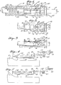
- the numeral 10 indicates a length of metal tubing which is incorporated as part of the fuel line from the fuel tank to the fuel pump of a diesel engine.
- a heater assembly indicated generally at 12, is mounted on and is coaxial with the tube 10. The heater assembly is preferably positioned immediately adjacent to but upstream of the fuel filter (not shown) normally employed with'a diesel engine to remove particulate matter from the fuel before it is injected into the engine cylinders.
- the heater assembly includes an electrical resistance type heater element, indicated generally at 14, a thermostatic switch assembly, indicated generally at 16, and a tubular protective housing 18.
- the heating element 14 is preferably made in the form of a ribbon of stainless steel 22 forming the resistance heater wound in a helix on a substrate 20 which electrically insulates the heating element from the tube.
- the substrate is made of a thin thermally conductive electrically insulating material.
- the heating element is made of a stainless steel and is bonded to the substrate to increase heat transfer through the substrate to the tube.
- the heating element 14 is surrounded by an insulating fiber 24 to insure efficient heat transfer to the tube and the fuel flowing through the tube with minimum loss to the environment.
- One end of the heater ribbon 22 is spot welded or otherwise directly attached to the tube to provide an electrical ground.
- the other end of the heater ribbon 22 is connected to a lead 26 which electrically connects the heater to an external power lead 28 through the thermostatic switch assembly 16 in the manner hereinafter described.
- the switch assembly 16 includes a substantially spool-shaped molded plastic frame 30 having a central longitudinal opening through which the tube 10 passes.
- the top of the frame' is open to expose a portion of the tube.
- the tube 10 is preferably flattened slightly on one side, as indicated at 31, opposite the opening of the top of the frame to provide clearance for the switch assembly.
- the open top of the frame is bridged by a metal support member 32.
- the metal support member 32 is channel shaped at one end with flanges 34 on either side which are riveted or otherwise secured to the open top of the frame 30.
- a bimetal thermal element 36 is spot welded at one end or otherwise secured to the underside of the frame member 32 so as to be adjacent to the exposed portion of the tube 10.
- the bimetal element 36 may be curved slightly to bring it closer to the tube 10.
- the free end of the bimetal element extends beyond the end of the frame member 32 and is bifurcated to form two upturned fingers 38. These fingers are notched at 40 to provide a pivot point or fulcrum for a U-shaped contact arm 42 which supports a moving contact 44 of an electrical switch.
- a tension spring 46 is connected at one end to the outer end of the frame member 32 and at the other end to the outer end of the switch arm 42.
- the spring 46 provides an over-center action as the bimetal element 36 moves the pivot notch 40 toward or away from the tube as it becomes colder or hotter in temperature.
- the bimetal element 36 is in its normal position under high ambient temperature conditions. As the ambient temperature drops, the bimetal element 36 moves closer to the tube causing the pivot notches 40 to move below the center line of the spring 46 and causing the arm to rotate the moving contact 44 upwardly against a fixed electrical contact 48, thus closing the switch.
- the fixed contact 48 is preferably mounted on a leaf spring 50 secured to a metal contact member 52 which bridges the tube and is secured on either side to the open top portion of the frame 30. Movement of the fixed contact 48 and supporting leaf spring 50 is limited by a stop 54 which is integral with the contact member 52.
- the leaf spring 50 is provided to insure that uniform contact pressure between the fixed contact 48 and moving contact 44 is maintained as the bimetal moves before the contact 44 is moved from the closed position to the open position.
- the switch 16 can be calibrated by a set screw 56 which threadedly engages the plastic frame member 30 and engages an arm 58 connected to the bridging frame member 32. Adjustment of the screw 56 tilts the arm 58 bending the outer top portion of the frame member 32, thereby shifting the end of the over-center spring 46. This has the effect of changing the position of the bimetal element at which the spring 46 snaps over center to open or close the switch.
- a potting compound having good thermal conductive properties but providing good electrical insulation may be injected in the space between the tube and the fixed end of the bimetal element 36, as indicated at 60.
- the power lead 2h is directly connected to the switch contact member 52 so that when the switch contacts are closed, an electrical circuit is completed between the lead 28 and the lead 26 going to the heater, the switch providing a current path from the fixed contact 48 to the moving contact 44 through the switch arm 42 and bimetal element 36.
- a piece of electrical tape or other insulating material may be secured to the under side of the bimetal element, as indicated at 62, to prevent any electrical contact between the tube and bimetal element when the switch contacts are closed, thus preventing any short to ground.
- the thermostatic switch is shown in simplified diagramatic form in FIG. 4 to better illustrate its construction and mode of operation. It will be readily apparent from FIG. 4 that as the bimetal element 36 moves down, the pivot notch 40 moves the ends of the U-shaped contact arm 42 down below the center line of the spring 46. This causes the spring 46 to pull the moving contact 44 upwardly against the fixed contact 48, compressing the leaf spring 50 and moving the contact 48 against the member 52. As the bimetal element 36 heats up, the notch 40 is moved upwardly above the center line of the spring 46, causing the spring 46 to pull the moving contact 44 downwardly against a stop 64.
- the arm of the frame member 32 to which the spring is attached may be a bimetal material in which case the end of the spring is moved up and down with temperature to cause an over-center action in moving the contact 44 between the stop 64 and the fixed contact 48.
- both the elements 32 and 36 may be constructed of bimetal. If they bend in opposite directions releative to each other with a given temperature change, this will increase the sensitivity of the switch. If they bend the same direction, this reduces the sensitivity of the switch and may be used to compensate for variations in ambient conditions if this is desirable.
- the thermostatic switch can be further modified as shown in FIG. 5 to provide a resistance heating element 66 attached to the bimetal element 36 to apply heat to the bimetal.
- the heater 66 may be used either to operate the switch as a relay from an external electrical control of the heater 66 or may be used as an anticipator to reduce the magnitude of the hysteresis or "dead" zone and increase the sensitivity of the switch to changes in the temperature of the tube 10. By applying a current to the heater 66, the switch can be caused to open or close. In the case of the relay of FIG. 5, it may be desirable to reverse the bimetal beyond the heater to provide ambient temperature compensation or make the arm of the frame member 32 of bimetal, as described above.
- the present invention provides a fuel heater having a bimetal actuator that provides a unique thermal snap-action switch.
- the switch mechanism has high contact force and maintains high contact force until the instant of snap and has good contact wipe action.
- the snap-action produces positive closure and an operating dead band that greatly reduces the number of actuations, thereby providing a heater control having long operating life.
- the fuel heater has several built-in protection features.
- the thermal element responds directly to fuel temperature because the thin heat conductive wall of the tube provides close thermal coupling. Also the fuel passes the thermal switch before it is heated by the heater. Therefore, the switch will remain closed as long as the ambient temperature of the fuel is below the critical level.
- the thermostatic switch will sense the rise in temperature of the tube from the heat generated by the heater and shut off power. Once fuel flows or the heater has cooled sufficiently, the heater will turn on again.
Landscapes
- Engineering & Computer Science (AREA)
- Chemical & Material Sciences (AREA)
- Combustion & Propulsion (AREA)
- Mechanical Engineering (AREA)
- General Engineering & Computer Science (AREA)
- Feeding And Controlling Fuel (AREA)
- Control Of Temperature (AREA)
- Resistance Heating (AREA)
- Thermally Actuated Switches (AREA)
Applications Claiming Priority (2)
| Application Number | Priority Date | Filing Date | Title |
|---|---|---|---|
| US17491680A | 1980-08-04 | 1980-08-04 | |
| US174916 | 1980-08-04 |
Publications (2)
| Publication Number | Publication Date |
|---|---|
| EP0045507A2 true EP0045507A2 (de) | 1982-02-10 |
| EP0045507A3 EP0045507A3 (de) | 1982-08-04 |
Family
ID=22638053
Family Applications (1)
| Application Number | Title | Priority Date | Filing Date |
|---|---|---|---|
| EP81106067A Withdrawn EP0045507A3 (de) | 1980-08-04 | 1981-08-03 | Brennstoffheizgerät für Diesel-Motoren |
Country Status (2)
| Country | Link |
|---|---|
| EP (1) | EP0045507A3 (de) |
| JP (1) | JPS5756656A (de) |
Cited By (4)
| Publication number | Priority date | Publication date | Assignee | Title |
|---|---|---|---|---|
| EP0101560A3 (de) * | 1982-07-19 | 1985-01-09 | Technar Incorporated | Thermistorgesteuerter Brennstoffvorwärmer |
| GB2272729A (en) * | 1992-11-05 | 1994-05-25 | Calvo Jose Manuel Esteban | Heating i.c.engine fuel |
| EP1209346A3 (de) * | 2000-11-27 | 2003-12-03 | Roberto Pelati | Vorrichtung zur verbesserung des verbrennungswirkungsgrades einer brennkraftmaschine |
| EP1795734A3 (de) * | 2005-12-09 | 2009-09-09 | Mahle International GmbH | Steuerungsvorrichtung einer Heizeinrichtung |
Families Citing this family (5)
| Publication number | Priority date | Publication date | Assignee | Title |
|---|---|---|---|---|
| JPS6365212A (ja) * | 1986-09-08 | 1988-03-23 | Isuzu Motors Ltd | 液体燃料気化装置 |
| JPS6365215A (ja) * | 1986-09-08 | 1988-03-23 | Isuzu Motors Ltd | 液体燃料気化装置 |
| JPS63140214A (ja) * | 1986-11-29 | 1988-06-11 | Isuzu Motors Ltd | 暖房装置の燃料加熱装置 |
| JP2636279B2 (ja) * | 1987-11-27 | 1997-07-30 | 株式会社デンソー | 燃料加熱装置 |
| WO2010104424A1 (en) * | 2009-03-13 | 2010-09-16 | Powercell Sweden Ab | Fuel injection device and method for a fuel reforme |
Family Cites Families (9)
| Publication number | Priority date | Publication date | Assignee | Title |
|---|---|---|---|---|
| FR488963A (fr) * | 1918-02-19 | 1918-12-03 | Caleb Edson Summers | Perfectionnements aux dispositifs d'amorcage des moteurs |
| FR576434A (fr) * | 1924-01-29 | 1924-08-20 | Dispositif applicable aux moteurs à combustion interne permettant d'utiliser pour leur alimentation tous combustibles hydrocarburés y compris les huiles lourdes | |
| US1756008A (en) * | 1930-01-28 | 1930-04-22 | Martin C Pizzaia | Fuel heater |
| FR872542A (fr) * | 1940-10-29 | 1942-06-11 | Réchauffeur électrique pour tous les carburants utilisés dans les moteurs à explosion | |
| FR904581A (fr) * | 1944-05-25 | 1945-11-09 | Dispositif réchauffeur de combustible, applicable aux carburateurs de moteurs à combustion interne pour le démarrage à froid | |
| US3019325A (en) * | 1958-12-15 | 1962-01-30 | Frank S Clouse | Fuel heating device |
| JPS5088717U (de) * | 1973-12-19 | 1975-07-28 | ||
| JPS54133209U (de) * | 1978-03-09 | 1979-09-14 | ||
| JPS5939179Y2 (ja) * | 1979-06-21 | 1984-10-31 | 日産自動車株式会社 | デイ−ゼルエンジンの燃料フイルタ装置 |
-
1981
- 1981-08-03 EP EP81106067A patent/EP0045507A3/de not_active Withdrawn
- 1981-08-03 JP JP56120791A patent/JPS5756656A/ja active Granted
Cited By (5)
| Publication number | Priority date | Publication date | Assignee | Title |
|---|---|---|---|---|
| EP0101560A3 (de) * | 1982-07-19 | 1985-01-09 | Technar Incorporated | Thermistorgesteuerter Brennstoffvorwärmer |
| GB2272729A (en) * | 1992-11-05 | 1994-05-25 | Calvo Jose Manuel Esteban | Heating i.c.engine fuel |
| GB2272729B (en) * | 1992-11-05 | 1996-05-15 | Calvo Jose Manuel Esteban | An electronically controlled fuel pretreatment apparatus |
| EP1209346A3 (de) * | 2000-11-27 | 2003-12-03 | Roberto Pelati | Vorrichtung zur verbesserung des verbrennungswirkungsgrades einer brennkraftmaschine |
| EP1795734A3 (de) * | 2005-12-09 | 2009-09-09 | Mahle International GmbH | Steuerungsvorrichtung einer Heizeinrichtung |
Also Published As
| Publication number | Publication date |
|---|---|
| JPH0259301B2 (de) | 1990-12-12 |
| JPS5756656A (en) | 1982-04-05 |
| EP0045507A3 (de) | 1982-08-04 |
Similar Documents
| Publication | Publication Date | Title |
|---|---|---|
| US4424422A (en) | Thermostatically controlled electric diesel fuel heater | |
| US4131657A (en) | Electric automotive choke | |
| US4208570A (en) | Thermostatically controlled electric engine coolant heater | |
| EP0045507A2 (de) | Brennstoffheizgerät für Diesel-Motoren | |
| US4433231A (en) | Electric iron having stacked thermostat assembly with integral overtemperature protection control | |
| KR950001159A (ko) | 주변온도 보상장치를 갖는 열응답 밸브 | |
| CA2099952A1 (en) | Adjustable cycling switch for electric range | |
| GB2072469A (en) | Heater device applicable to a fuel filter | |
| US6597274B1 (en) | Bimetal snap disc thermostat with heaters | |
| US4337389A (en) | Glow plug control device for diesel engines | |
| US4400679A (en) | Snap acting switch for thermostats | |
| US2239540A (en) | Thermostatic control | |
| US6116569A (en) | Valve construction | |
| US4319214A (en) | Creepless, snap action thermostat | |
| US4892996A (en) | Thermostatically controlled in-line diesel fuel heater using a bimetal disc thermostat | |
| US2463891A (en) | Electric switch | |
| US4337451A (en) | Electrical switch construction, switch blade subassembly and methods of making the same | |
| EP0684623B1 (de) | Geräte mit Widerstandselemeten und Temperaturschutzvorrichtung zum Gebrauch dafür | |
| AU745178B2 (en) | Temperature-dependent switch | |
| US3801944A (en) | Temperature-compensated, thermal-activated time delay switch | |
| US2955185A (en) | Constant temperature apparatus | |
| KR102654526B1 (ko) | 발열 호스 안전장치 | |
| KR100508135B1 (ko) | 모터시동및보호장치 | |
| US4434414A (en) | Snap-acting thermal relay | |
| US5844465A (en) | Temperature compensated time-delay switch |
Legal Events
| Date | Code | Title | Description |
|---|---|---|---|
| PUAI | Public reference made under article 153(3) epc to a published international application that has entered the european phase |
Free format text: ORIGINAL CODE: 0009012 |
|
| AK | Designated contracting states |
Designated state(s): DE FR GB IT |
|
| PUAL | Search report despatched |
Free format text: ORIGINAL CODE: 0009013 |
|
| AK | Designated contracting states |
Designated state(s): DE FR GB IT |
|
| 17P | Request for examination filed |
Effective date: 19830201 |
|
| STAA | Information on the status of an ep patent application or granted ep patent |
Free format text: STATUS: THE APPLICATION IS DEEMED TO BE WITHDRAWN |
|
| 18D | Application deemed to be withdrawn |
Effective date: 19840703 |
|
| RIN1 | Information on inventor provided before grant (corrected) |
Inventor name: BELL, LON EDWARD Inventor name: GRUBER, WILLIAM PAUL |