EP0045535B1 - Tauchmesskopf zur Benützung in flüssigen Metallen - Google Patents
Tauchmesskopf zur Benützung in flüssigen Metallen Download PDFInfo
- Publication number
- EP0045535B1 EP0045535B1 EP81200750A EP81200750A EP0045535B1 EP 0045535 B1 EP0045535 B1 EP 0045535B1 EP 81200750 A EP81200750 A EP 81200750A EP 81200750 A EP81200750 A EP 81200750A EP 0045535 B1 EP0045535 B1 EP 0045535B1
- Authority
- EP
- European Patent Office
- Prior art keywords
- measuring
- tube
- immersion
- probe
- projection
- Prior art date
- Legal status (The legal status is an assumption and is not a legal conclusion. Google has not performed a legal analysis and makes no representation as to the accuracy of the status listed.)
- Expired
Links
- 239000000523 sample Substances 0.000 title claims abstract description 29
- 238000007654 immersion Methods 0.000 title claims abstract description 16
- 229910001338 liquidmetal Inorganic materials 0.000 title claims abstract description 10
- 239000003779 heat-resistant material Substances 0.000 claims abstract description 7
- 230000001681 protective effect Effects 0.000 claims description 5
- 229910010293 ceramic material Inorganic materials 0.000 claims description 2
- 239000000463 material Substances 0.000 abstract 1
- 229910052751 metal Inorganic materials 0.000 description 7
- 239000002184 metal Substances 0.000 description 7
- 238000005259 measurement Methods 0.000 description 5
- PNEYBMLMFCGWSK-UHFFFAOYSA-N Alumina Chemical compound [O-2].[O-2].[O-2].[Al+3].[Al+3] PNEYBMLMFCGWSK-UHFFFAOYSA-N 0.000 description 3
- 239000004568 cement Substances 0.000 description 2
- 239000000919 ceramic Substances 0.000 description 2
- 238000005192 partition Methods 0.000 description 2
- 239000005995 Aluminium silicate Substances 0.000 description 1
- PZZYQPZGQPZBDN-UHFFFAOYSA-N aluminium silicate Chemical compound O=[Al]O[Si](=O)O[Al]=O PZZYQPZGQPZBDN-UHFFFAOYSA-N 0.000 description 1
- 229910000323 aluminium silicate Inorganic materials 0.000 description 1
- 235000012211 aluminium silicate Nutrition 0.000 description 1
- QVGXLLKOCUKJST-UHFFFAOYSA-N atomic oxygen Chemical compound [O] QVGXLLKOCUKJST-UHFFFAOYSA-N 0.000 description 1
- 239000004020 conductor Substances 0.000 description 1
- 238000001816 cooling Methods 0.000 description 1
- 230000002939 deleterious effect Effects 0.000 description 1
- 239000000835 fiber Substances 0.000 description 1
- 238000004519 manufacturing process Methods 0.000 description 1
- 239000002923 metal particle Substances 0.000 description 1
- 229910052760 oxygen Inorganic materials 0.000 description 1
- 239000001301 oxygen Substances 0.000 description 1
- RVTZCBVAJQQJTK-UHFFFAOYSA-N oxygen(2-);zirconium(4+) Chemical compound [O-2].[O-2].[Zr+4] RVTZCBVAJQQJTK-UHFFFAOYSA-N 0.000 description 1
- 239000010453 quartz Substances 0.000 description 1
- 239000011819 refractory material Substances 0.000 description 1
- 238000007789 sealing Methods 0.000 description 1
- VYPSYNLAJGMNEJ-UHFFFAOYSA-N silicon dioxide Inorganic materials O=[Si]=O VYPSYNLAJGMNEJ-UHFFFAOYSA-N 0.000 description 1
- 239000002893 slag Substances 0.000 description 1
- 238000003466 welding Methods 0.000 description 1
- 229910001928 zirconium oxide Inorganic materials 0.000 description 1
Images
Classifications
-
- G—PHYSICS
- G01—MEASURING; TESTING
- G01K—MEASURING TEMPERATURE; MEASURING QUANTITY OF HEAT; THERMALLY-SENSITIVE ELEMENTS NOT OTHERWISE PROVIDED FOR
- G01K1/00—Details of thermometers not specially adapted for particular types of thermometer
- G01K1/08—Protective devices, e.g. casings
- G01K1/10—Protective devices, e.g. casings for preventing chemical attack
- G01K1/105—Protective devices, e.g. casings for preventing chemical attack for siderurgical use
-
- G—PHYSICS
- G01—MEASURING; TESTING
- G01K—MEASURING TEMPERATURE; MEASURING QUANTITY OF HEAT; THERMALLY-SENSITIVE ELEMENTS NOT OTHERWISE PROVIDED FOR
- G01K7/00—Measuring temperature based on the use of electric or magnetic elements directly sensitive to heat ; Power supply therefor, e.g. using thermoelectric elements
- G01K7/02—Measuring temperature based on the use of electric or magnetic elements directly sensitive to heat ; Power supply therefor, e.g. using thermoelectric elements using thermoelectric elements, e.g. thermocouples
- G01K7/025—Measuring temperature based on the use of electric or magnetic elements directly sensitive to heat ; Power supply therefor, e.g. using thermoelectric elements using thermoelectric elements, e.g. thermocouples expendable thermocouples
Definitions
- This invention relates to immersion measuring probes for use in liquid metals.
- immersion probes For measuring e.g. the temperature and/or oxygen content of a liquid metal mostly immersion probes are used which traditionally consist of a tube whose extremity to be immersed is sealed by a stopper-shaped measuring head carrying one or more measuring elements as well as a corresponding numbers of connectors.
- the measuring elements protrude from the measuring head at the side of the latter to be immersed and the connectors retrude at the other side.
- a measuring probe Upon use such a measuring probe is slid over a supporting lance whereby a connector takes contact with a contact block provided forthat purpose in the lance. Said contact block is connected to a measuring instrument through electric conductors running through the lance.
- the protruding parts of the measuring elements are usually protected by metal caps mounted on the measuring heads, which caps melt away upon immersion in the liquid metal.
- the tubes are mostly made of cardboard. Sometimes they are provided with an insulating protective sleeve in order to prevent splashing and vibrations on immersion.
- Measuring probes as described above are only suitable for single use mainly because metal particles adhere to the measuring elements when the probes are withdrawn from the liquid metal after the first measurement whereby a second measurement becomes impossible.
- the main object of the invention is to avoid this drawback and thus to allow several measurements with one and the same immersion probe.
- Another object of the invention is the simplification in many cases of the manufacture of the immersion probe or in lowering the costprice of it.
- an immersion measuring probe for use in liquid metals, of the type comprising a measuring head carrying at least one measuring element, the head being fixed to an extremity of a tube which tube is arranged to be slid onto a supporting lance, said head having at least one projection partly surrounding the measuring element and extending from the head farther than said measuring element and made of a heat-resistant material, is characterized in that said heat-resistant material is a ceramic material with a density not exceeding substantially 2,5 g/cm 3 , said projection being fully spaced away from said measuring element and at a distance therefrom in a direction perpendicular ⁇ to the axis of the probe, not larger than substantially 2,5 cm, the thickness of the projection in a direction perpendicular to the axis of the probe amounting to substantially 10 mm.
- the measuring element indeed has to be the extreme part of the probe in order to expose it optimally to the liquid metal
- the extension(s) or projection(s) of a probe according to the present invention have absolutely no deleterious effect on the measurement and that no metal or slag adhered to the measuring element when the probe was withdrawn from the bath.
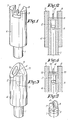
- the measuring probe according to Figures 1 and 2 consists of a cardboard tube 1, suited for being slid over a supporting lance (not shown) and at one side is provided with a measuring head 2.
- This measuring head 2 is in the form of a stopper and seals the cardboard tube 1.
- At the side to be immersed in the metal bath it is insulated by a layer 3 of a well insulating refractory material such as refractory cement or ceramic fibres.
- the measuring head 2 contains the measuring element being in this case a thermocouple 4, whereas at the other side it is provided with a connector 5.
- the side of the measuring probe to be immersed is enveloped by an insulating sleeve 6 made of a ceramic fibre such as aluminium oxide, aluminium silicate, zirconium oxide, quartz, etc. which has a wall thickness of about 10 mm ( ⁇ 20%).
- the wall of sleeve 6 extends itself at the place of the measuring element by two symmetrically placed projections 7 and 8, which reach e.g. 0.5 cm farther than the small U-shaped thermocouple tube.
- sleeve 6 is provided with a partition 12 with central opening 13 through which the measuring element protrudes. A complete sealing is achieved by means of a small amount of refractory cement 14.
- partition 12 results therein that the measuring head is still better insulated and that the so-called cold weldings will thus be heated less.
- the projections 7 and 8 formed by two small plates made of a heat-resistant material of low density are directly carried by the measuring head 2 wherein they are partly embedded.
- the heat-resistant material chosen for the projections and/or the sleeve according to the invention should have a density not exceeding about 2.5 g/cm 3 . Experimentally it has been found that if the density is larger than this value the projections have too large a cooling action on the liquid metal surrounding the measuring element.
- the distance between projection and measuring element measured in a direction perpendicular to the axis of the probe should not exceed about 2.5 cm in order to be sure to avoid any adhesion of metal to the measuring element.
Landscapes
- Physics & Mathematics (AREA)
- General Physics & Mathematics (AREA)
- Sampling And Sample Adjustment (AREA)
- Investigating Or Analyzing Non-Biological Materials By The Use Of Chemical Means (AREA)
- Electrical Discharge Machining, Electrochemical Machining, And Combined Machining (AREA)
- Investigating And Analyzing Materials By Characteristic Methods (AREA)
Claims (4)
Priority Applications (1)
| Application Number | Priority Date | Filing Date | Title |
|---|---|---|---|
| AT81200750T ATE15941T1 (de) | 1980-07-22 | 1981-07-02 | Tauchmesskopf zur benuetzung in fluessigen metallen. |
Applications Claiming Priority (2)
| Application Number | Priority Date | Filing Date | Title |
|---|---|---|---|
| BE2/58663A BE884405A (nl) | 1980-07-22 | 1980-07-22 | Dompelmeetsonde voor metingen in vloeibare metalen |
| BE2058663 | 1980-07-22 |
Publications (3)
| Publication Number | Publication Date |
|---|---|
| EP0045535A2 EP0045535A2 (de) | 1982-02-10 |
| EP0045535A3 EP0045535A3 (en) | 1982-02-17 |
| EP0045535B1 true EP0045535B1 (de) | 1985-10-02 |
Family
ID=3865511
Family Applications (1)
| Application Number | Title | Priority Date | Filing Date |
|---|---|---|---|
| EP81200750A Expired EP0045535B1 (de) | 1980-07-22 | 1981-07-02 | Tauchmesskopf zur Benützung in flüssigen Metallen |
Country Status (4)
| Country | Link |
|---|---|
| EP (1) | EP0045535B1 (de) |
| AT (1) | ATE15941T1 (de) |
| AU (1) | AU546239B2 (de) |
| DE (1) | DE3172511D1 (de) |
Families Citing this family (5)
| Publication number | Priority date | Publication date | Assignee | Title |
|---|---|---|---|---|
| CA1209367A (en) * | 1982-10-08 | 1986-08-12 | Omer P.I. Cure | Immersion measuring probe for use in molten metals |
| US5796489A (en) * | 1993-10-20 | 1998-08-18 | Emmrich; Roland | Hollow vacuum-tight ceramic shaped body |
| DE102005060493B3 (de) * | 2005-12-15 | 2006-11-30 | Heraeus Electro-Nite International N.V. | Messsonde |
| DE102013201179A1 (de) | 2013-01-24 | 2014-08-07 | Dekema Dental-Keramiköfen GmbH | Thermoelement |
| FR3030731B1 (fr) * | 2014-12-18 | 2017-01-06 | Electricite De France | Outil et procede de pose d'un thermocouple |
Family Cites Families (5)
| Publication number | Priority date | Publication date | Assignee | Title |
|---|---|---|---|---|
| US2374377A (en) * | 1943-04-05 | 1945-04-24 | Us Steel Corp Of Delaware | Pyrometer tube |
| US3011005A (en) * | 1959-08-21 | 1961-11-28 | Electro Nite Engineering Compa | Thermocouple |
| GB1033937A (en) * | 1963-07-08 | 1966-06-22 | Thermal Syndicate Ltd | An expendable thermo-couple head for use in high temperature measurements |
| DE1573249A1 (de) * | 1965-04-06 | 1970-08-13 | Leeds & Northrup Co | Verbrauchbare Temperaturfuehl-Eintaucheinheit |
| US3497398A (en) * | 1966-01-17 | 1970-02-24 | Electro Nite | Bullet-shaped drop thermocouple |
-
1981
- 1981-07-02 AT AT81200750T patent/ATE15941T1/de not_active IP Right Cessation
- 1981-07-02 DE DE8181200750T patent/DE3172511D1/de not_active Expired
- 1981-07-02 EP EP81200750A patent/EP0045535B1/de not_active Expired
- 1981-07-14 AU AU73022/81A patent/AU546239B2/en not_active Ceased
Non-Patent Citations (2)
| Title |
|---|
| G G Hawley, "The Condensed Chemical Dictionary", ninth edition, 1977, van Nostrand Reinhold Company, New York * |
| H.Scholze, "Glas-Natur, Struktur und Eigenschaften", second edition , 1977, Springer Verlag, Berlin. * |
Also Published As
| Publication number | Publication date |
|---|---|
| ATE15941T1 (de) | 1985-10-15 |
| EP0045535A3 (en) | 1982-02-17 |
| EP0045535A2 (de) | 1982-02-10 |
| AU7302281A (en) | 1982-01-28 |
| AU546239B2 (en) | 1985-08-22 |
| DE3172511D1 (en) | 1985-11-07 |
Similar Documents
| Publication | Publication Date | Title |
|---|---|---|
| EP0108431B1 (de) | Immersionsmessprobe für Messungen in flüssigen Metallen | |
| AU622743B2 (en) | Thermocouple-type temperature sensor and method of measuring temperature of molten steel | |
| CA1326377C (en) | Protective tube for a temperature sensor | |
| US4377347A (en) | Method for measuring temperature of molten metal received in vessel | |
| KR950006015B1 (ko) | 온도 감지 장치 | |
| US5275488A (en) | BOF drop-in thermocouple | |
| CA2188666C (en) | Drop-in immersion probe | |
| US4269397A (en) | Method for measuring the thickness of a refractory in a metallurgical apparatus | |
| US4198279A (en) | Oxygen sensor mounting structure | |
| US3758397A (en) | Apparatus for oxygen determination | |
| US3668099A (en) | Apparatus for measuring oxygen content of a fluid | |
| US4365788A (en) | Process and apparatus for determining the level of molten metal in a metallurgical vessel, the temperature of the molten metal and the extent of wear of the refractory lining of the vessel | |
| EP0045535A2 (de) | Tauchmesskopf zur Benützung in flüssigen Metallen | |
| US4358630A (en) | Replacement cap for repeating use thermocouple | |
| US3802926A (en) | Thermocouple with spaced electrically insulating sheaths | |
| US4468009A (en) | Refractory protection tube for immersion molten metal devices | |
| JP5299032B2 (ja) | 溶鋼の連続測温方法 | |
| JPH0472183B2 (de) | ||
| KR100337988B1 (ko) | 전기화학적활성도를측정하기위한방법 | |
| JPH10501628A (ja) | 電気−化学的な活動度の測定方法 | |
| JPH0318945Y2 (de) | ||
| JPH0315729A (ja) | 金属溶湯の温度測定装置 | |
| JPS60220852A (ja) | 転炉内脱炭中溶融金属の酸素含有量と温度を測定する装置 | |
| JP4623481B2 (ja) | 熱電対 | |
| US3505125A (en) | Reusable molten metal temperature measuring apparatus |
Legal Events
| Date | Code | Title | Description |
|---|---|---|---|
| PUAI | Public reference made under article 153(3) epc to a published international application that has entered the european phase |
Free format text: ORIGINAL CODE: 0009012 |
|
| PUAL | Search report despatched |
Free format text: ORIGINAL CODE: 0009013 |
|
| AK | Designated contracting states |
Designated state(s): AT CH DE FR GB IT NL SE |
|
| AK | Designated contracting states |
Designated state(s): AT CH DE FR GB IT NL SE |
|
| 17P | Request for examination filed |
Effective date: 19820205 |
|
| ITF | It: translation for a ep patent filed | ||
| GRAA | (expected) grant |
Free format text: ORIGINAL CODE: 0009210 |
|
| AK | Designated contracting states |
Designated state(s): AT CH DE FR GB IT LI NL SE |
|
| REF | Corresponds to: |
Ref document number: 15941 Country of ref document: AT Date of ref document: 19851015 Kind code of ref document: T |
|
| REF | Corresponds to: |
Ref document number: 3172511 Country of ref document: DE Date of ref document: 19851107 |
|
| ET | Fr: translation filed | ||
| PGFP | Annual fee paid to national office [announced via postgrant information from national office to epo] |
Ref country code: AT Payment date: 19860627 Year of fee payment: 6 |
|
| PLBE | No opposition filed within time limit |
Free format text: ORIGINAL CODE: 0009261 |
|
| STAA | Information on the status of an ep patent application or granted ep patent |
Free format text: STATUS: NO OPPOSITION FILED WITHIN TIME LIMIT |
|
| 26N | No opposition filed | ||
| PGFP | Annual fee paid to national office [announced via postgrant information from national office to epo] |
Ref country code: NL Payment date: 19870731 Year of fee payment: 7 |
|
| PG25 | Lapsed in a contracting state [announced via postgrant information from national office to epo] |
Ref country code: GB Effective date: 19890702 Ref country code: AT Effective date: 19890702 |
|
| PG25 | Lapsed in a contracting state [announced via postgrant information from national office to epo] |
Ref country code: SE Effective date: 19890703 |
|
| PG25 | Lapsed in a contracting state [announced via postgrant information from national office to epo] |
Ref country code: LI Effective date: 19890731 Ref country code: CH Effective date: 19890731 |
|
| PG25 | Lapsed in a contracting state [announced via postgrant information from national office to epo] |
Ref country code: NL Effective date: 19900201 |
|
| GBPC | Gb: european patent ceased through non-payment of renewal fee | ||
| NLV4 | Nl: lapsed or anulled due to non-payment of the annual fee | ||
| PG25 | Lapsed in a contracting state [announced via postgrant information from national office to epo] |
Ref country code: FR Free format text: LAPSE BECAUSE OF NON-PAYMENT OF DUE FEES Effective date: 19900330 |
|
| REG | Reference to a national code |
Ref country code: CH Ref legal event code: PL |
|
| PG25 | Lapsed in a contracting state [announced via postgrant information from national office to epo] |
Ref country code: DE Effective date: 19900403 |
|
| REG | Reference to a national code |
Ref country code: FR Ref legal event code: ST |
|
| EUG | Se: european patent has lapsed |
Ref document number: 81200750.8 Effective date: 19900418 |