EP0045545A2 - Vorrichtung zum Verschieben eines elektrischen Schalters in seinem Schrank - Google Patents
Vorrichtung zum Verschieben eines elektrischen Schalters in seinem Schrank Download PDFInfo
- Publication number
- EP0045545A2 EP0045545A2 EP81200825A EP81200825A EP0045545A2 EP 0045545 A2 EP0045545 A2 EP 0045545A2 EP 81200825 A EP81200825 A EP 81200825A EP 81200825 A EP81200825 A EP 81200825A EP 0045545 A2 EP0045545 A2 EP 0045545A2
- Authority
- EP
- European Patent Office
- Prior art keywords
- switch
- slider
- door
- carriage
- worm
- Prior art date
- Legal status (The legal status is an assumption and is not a legal conclusion. Google has not performed a legal analysis and makes no representation as to the accuracy of the status listed.)
- Granted
Links
Images
Classifications
-
- H—ELECTRICITY
- H02—GENERATION; CONVERSION OR DISTRIBUTION OF ELECTRIC POWER
- H02B—BOARDS, SUBSTATIONS OR SWITCHING ARRANGEMENTS FOR THE SUPPLY OR DISTRIBUTION OF ELECTRIC POWER
- H02B11/00—Switchgear having carriage withdrawable for isolation
- H02B11/12—Switchgear having carriage withdrawable for isolation with isolation by horizontal withdrawal
- H02B11/127—Withdrawal mechanism
- H02B11/133—Withdrawal mechanism with interlock
Definitions
- This invention relates to an electric switch arranged in a cupboard in which it can be displaced and from which it can even be completely withdrawn.
- this invention relates to a device for displacing the switch in its attendant compartment within the cupboard, in which it can.take either a disconnected position, that is disconnected from the main, or a connected position in which it is connected to the main.
- the cupboard compartment in which the switch is housed is normally closed by a door through which the switch can be accessed to from the outside for being withdrawn and for possible checking operations.
- An objective of the present invention is thus to provide a device which can simply be constructed and is highly reliable, such as.to enable the displacement ma- noeuver of the switch in the interior of the cupboard compartment with the door closed and acting from the outside and which, in addition, be such as to ensure that such an operation is possible only when the switch is placed willfully in the OFF position.
- a device for displacing a switch displaceable on guiding ways in a compartment of a cupboard which can be shut by a door said device being characterized in that it comprises a carriage mounted in said compartment and which can be shifted from the "disconnected” position to the "connected” position of the switch relative to the main, and vice versa, means for controlling the displacement of said carriage in either direction, a first member jutting from the switch and capable of being engaged by said carriage for shifting the switch, a second member jutting from the switch and adapted to take two positions, one of shorter projection and the other of longer projection, means incorporated in the switch for preventing said second member from taking the position of shorter projection when the switch is ON and for preventing the closure of the switch when said second member is in the position of shorter projection, a guideway along the route of the switch displacement cooperating with said second projecting member to keep it in the position of shorter projection, two notches in said guideway in correspondence with the "connected " and "disconnected
- said means for controlling the displacement of the driving carriage may consist of an endless screw supported for rotation in either direction in the compartment and engaged by a nut formed in the carriage.
- Such an endless screw is aligned with the door bore and has, at a determined distance from the latter, a square cross-sectional portion for being actuated by a specially provided wrench.
- This square cross-sectional portion can be accessed to only if the slider has pre-1 vlously been displaced, and such a displacement can be brought about by urging with the actuating spanner aforementioned, as introduced through the door bore.
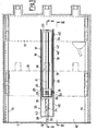
- a compartment 10 is provided, which can be frontally closed by a door 11 and is intended to house a switch, generally indicated by its outline 12.
- a worm 21 is borne so as to be freely rotated in both directions.
- the axis of said screw is parallel to the guideways 13, 14 and is aligned with a bore 22 formed through the door 11 when the latter is shut.
- the screw 21 is prevented from being shifted axially and is extended, after having crossed the wall 19, by a smooth circular shank 23 until coming into registry with the bore 22 through the door 11.
- the shank 23 has a portion 24 with a square cross-sectional outline which is adapted to be engaged by a tubular wrench 25 (best seen in FIGURE 4).
- a carriage is allowed to slide, which is engaged through a central through-nut 27 by the worm 21. It is apparent that, by turning the worm in either direction., the carriage 26 is shifted along its axis.
- the carriage 26 has at its top a transversal hollow space 28 which can be engaged by a first square- sectional pin 29 which juts downwards from the switch assembly 12.
- this pin 29 will be dubbed a driving pin, inasmuch as it is apparent that, when it is engaged in the hollow space 28 of the carriage 26 and the carriage is caused to travel,.it draws the entire switch assembly with it.
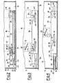
- This driving pin 29 can take two positions, viz.: a depressed position shown in FIGURE 2, wherein it can engage a hollow space 28 of the carriage 26, and a lifted position, wherein it is incapable of doing so but abuts a shoulder 30 of the carriage 26.
- the means for bringing the pin 29 to its lifted position and to hold it in certain situations is of no interest so that such means will not be described in detail or shown in the drawings.
- the switch 12 On the same transversal plane as the pin 29, the switch 12 has a second pin 31 which likewise juts downwards and is shifted laterally. Also this pin 31, which, due to its functions, will be dubbed a latching pin, may take two positions, one of shorter projection, and the other of longer projection relative to the switch 12. Its position of longer projection, as viewed in FIGURE 3, can be taken by the pin either by its own weight or by the bias of a spring (not shown).
- the internal mechanism of the switch 12 are so connected to a stop lever 32 as to take a position in which it holds the latching pin 31 in the depressed position when the contacts of the switch 12 are closed, and to take, instead, a position wherein the pin 31 can be lifted to its position of shorter projection only and exclusively when the switch contacts are open and the snap springs of the switch are unloaded. Also these internal linkages of the switch which bring about the two positions of the stopping lever 32 consistently with the closed or the open condition of the switch are not of immediate interest for the present invention, so that they are neither described in detail herein nor shown in the drawings. It ..
- a slider On the sidewalls 17, 18 of the guideway 16, there is slidably mounted a slider, generally indicated at 35, having the shape of a " U " with two sidewalls 36, 37 and a cross wall 38.
- Slider 35 is supported at least by the sidewall 18 of the guideway 16 by two pins 39, 40, which are secured to the sidewall 18 and are inserted into longitudinal slots 41, 42, as formed through the corresponding sidewall 37 of the slider 35.
- the length of these slots 41, 42 defines the stroke of possible displacement of the slider 35, which is normally held in the position shifted leftwards (as viewed in FIGURES 2, 3) by a spring 43 which acts between the cross wall 38 of the slider and the cross wall 19 of the fixed guideway 16.
- the shank 23 of the worm 21 freely passes through a bore 44 formed through the cross wall 38 of the slider 35 and that in the position of rest (shifted leftwards) of the latter, the square- sectional portion 24 of the worm 21 is in the .space between the cross walls 19 and 38, and thus cannot be directly accessed to on the side of the door 11.
- a tubular wrench 25 (see FIG.4), introduced through the bore 22 of the door 11 until contacting the wall 38 of the slider 35, the square portion 24 of the worm 21, it is required, at the outset, to push back the slider 35 by the same wrench 25 against the bias of the spring 43 until the squared portion 24 is unmasked and may be grasped by the tool.
- the sidewall 37 of the slider 35 has a top horizontal plane which is at the same level as the top plane of sidewall 18 of the guideway 16.
- the latching pin 31 of the switch cooperates with both these sidewalls of the guideway 16 and the slider 35, respectively.
- the sidewall 37 of the slider 35 has cammed grooves 45 and 46, which are formed, each, by a lower portion and an incline which rises to the top plane of the sidewall 37 in the direction towards the cross wall 38 of the slider 35.
- the screw can be rotated thereby and can cause the translational motion of the carriage 26 which drags with it the switch assembly 12 as a whole.
- the tubular wrench 25 is withdrawn so that the slider 35 is permitted to take its at rest position again, under the bias of the spring 43.
- the incline of its groove 46 permits that the latching pin 31 be gradually depressed so that it simultaneously enters the notch 34 of the fixed guideway 16.
- the switch 12 is latched in its "connected” position and can be closed by an appropriate control.
- the pin 31, as it lies in its position of longer projection cannot prevent the closing stroke of the switch 12 any longer.
- both the driving pin 29 be lifted for making it clear of the hollow space 28 of the carriage 26, and that the latching pin 31 be lifted to clear it of the notch 33 of the sidewall 18 of the fixed guideway 16. Lifting these pins is an operation which can be done also manually and the pin 31 can be lifted only if the switch is open.
Landscapes
- Engineering & Computer Science (AREA)
- Power Engineering (AREA)
- Power-Operated Mechanisms For Wings (AREA)
- Push-Button Switches (AREA)
Priority Applications (1)
| Application Number | Priority Date | Filing Date | Title |
|---|---|---|---|
| AT81200825T ATE10244T1 (de) | 1980-07-31 | 1981-07-20 | Vorrichtung zum verschieben eines elektrischen schalters in seinem schrank. |
Applications Claiming Priority (2)
| Application Number | Priority Date | Filing Date | Title |
|---|---|---|---|
| IT23842/80A IT1132041B (it) | 1980-07-31 | 1980-07-31 | Dispositivo per la translazione di un interruttore elettrico nel suo armadio di custodia |
| IT2384280 | 1980-07-31 |
Publications (3)
| Publication Number | Publication Date |
|---|---|
| EP0045545A2 true EP0045545A2 (de) | 1982-02-10 |
| EP0045545A3 EP0045545A3 (en) | 1982-08-04 |
| EP0045545B1 EP0045545B1 (de) | 1984-11-07 |
Family
ID=11210349
Family Applications (1)
| Application Number | Title | Priority Date | Filing Date |
|---|---|---|---|
| EP81200825A Expired EP0045545B1 (de) | 1980-07-31 | 1981-07-20 | Vorrichtung zum Verschieben eines elektrischen Schalters in seinem Schrank |
Country Status (8)
| Country | Link |
|---|---|
| EP (1) | EP0045545B1 (de) |
| AR (1) | AR225232A1 (de) |
| AT (1) | ATE10244T1 (de) |
| BR (1) | BR8104941A (de) |
| DE (1) | DE3167069D1 (de) |
| IT (1) | IT1132041B (de) |
| MX (1) | MX150784A (de) |
| NZ (1) | NZ197889A (de) |
Cited By (10)
| Publication number | Priority date | Publication date | Assignee | Title |
|---|---|---|---|---|
| EP0048042A3 (en) * | 1980-09-17 | 1982-08-04 | Ansaldo S.P.A. | Safety device for spring-controlled circuit breakers which are movable in a housing cubicle |
| FR2581805A1 (fr) * | 1985-05-07 | 1986-11-14 | Merlin Gerin | Disjoncteur debrochable multipolaire equipe d'un dispositif de desarmement et de declenchement automatique lors de l'extraction |
| EP0227586A1 (de) * | 1985-12-20 | 1987-07-01 | Siemens Aktiengesellschaft | Elektrische Schalteinrichtung mit einem Einschubrahmen und einem darin einsetzbaren Schaltgerät |
| AT389404B (de) * | 1983-04-06 | 1989-12-11 | Siemens Ag | Elektrisches schaltfeld mit einem schaltertraeger und einer gewindespindel |
| EP0621614A1 (de) * | 1993-04-21 | 1994-10-26 | Abb Sace Spa | Trennbarer Schalter |
| EP1227557A1 (de) * | 1999-07-27 | 2002-07-31 | Mitsubishi Denki Kabushiki Kaisha | Einschubeinheit für ein elektrisches Gerät |
| EP1231691A1 (de) * | 2001-02-02 | 2002-08-14 | Moeller GmbH | Auslösevorrichtung für einen ausfahrbaren Leistungsschalter |
| WO2013072371A1 (en) | 2011-11-17 | 2013-05-23 | Dow Corning Corporation | Silicone resins |
| WO2013072370A2 (en) | 2011-11-17 | 2013-05-23 | Dow Corning Corporation | Silicone resins comprising metallosiloxane |
| EP2228878A3 (de) * | 2009-03-11 | 2014-07-09 | LS Industrial Systems Co., Ltd | Vorrichtung zur Verhinderung des Rücklaufs oder Einfügens von Einschüben in einen Leistungsschalter |
Family Cites Families (3)
| Publication number | Priority date | Publication date | Assignee | Title |
|---|---|---|---|---|
| US2777024A (en) * | 1951-04-28 | 1957-01-08 | Westinghouse Electric Corp | Metal-enclosed switchgear |
| US3188414A (en) * | 1962-05-14 | 1965-06-08 | Gen Electric | Releasable stop means for a movable unit in a stationary enclosure |
| US4004113A (en) * | 1975-04-14 | 1977-01-18 | General Electric Company | Drawout apparatus for electrical switchboards |
-
1980
- 1980-07-31 IT IT23842/80A patent/IT1132041B/it active
-
1981
- 1981-07-20 AT AT81200825T patent/ATE10244T1/de active
- 1981-07-20 EP EP81200825A patent/EP0045545B1/de not_active Expired
- 1981-07-20 DE DE8181200825T patent/DE3167069D1/de not_active Expired
- 1981-07-21 MX MX188393A patent/MX150784A/es unknown
- 1981-07-30 NZ NZ197889A patent/NZ197889A/en unknown
- 1981-07-30 BR BR8104941A patent/BR8104941A/pt unknown
- 1981-07-30 AR AR286282A patent/AR225232A1/es active
Cited By (11)
| Publication number | Priority date | Publication date | Assignee | Title |
|---|---|---|---|---|
| EP0048042A3 (en) * | 1980-09-17 | 1982-08-04 | Ansaldo S.P.A. | Safety device for spring-controlled circuit breakers which are movable in a housing cubicle |
| AT389404B (de) * | 1983-04-06 | 1989-12-11 | Siemens Ag | Elektrisches schaltfeld mit einem schaltertraeger und einer gewindespindel |
| FR2581805A1 (fr) * | 1985-05-07 | 1986-11-14 | Merlin Gerin | Disjoncteur debrochable multipolaire equipe d'un dispositif de desarmement et de declenchement automatique lors de l'extraction |
| EP0227586A1 (de) * | 1985-12-20 | 1987-07-01 | Siemens Aktiengesellschaft | Elektrische Schalteinrichtung mit einem Einschubrahmen und einem darin einsetzbaren Schaltgerät |
| EP0621614A1 (de) * | 1993-04-21 | 1994-10-26 | Abb Sace Spa | Trennbarer Schalter |
| EP1227557A1 (de) * | 1999-07-27 | 2002-07-31 | Mitsubishi Denki Kabushiki Kaisha | Einschubeinheit für ein elektrisches Gerät |
| US6490149B2 (en) | 1999-07-27 | 2002-12-03 | Mitsubishi Denki Kabushiki Kaisha | Drawing apparatus for a drawer type electrical machinery |
| EP1231691A1 (de) * | 2001-02-02 | 2002-08-14 | Moeller GmbH | Auslösevorrichtung für einen ausfahrbaren Leistungsschalter |
| EP2228878A3 (de) * | 2009-03-11 | 2014-07-09 | LS Industrial Systems Co., Ltd | Vorrichtung zur Verhinderung des Rücklaufs oder Einfügens von Einschüben in einen Leistungsschalter |
| WO2013072371A1 (en) | 2011-11-17 | 2013-05-23 | Dow Corning Corporation | Silicone resins |
| WO2013072370A2 (en) | 2011-11-17 | 2013-05-23 | Dow Corning Corporation | Silicone resins comprising metallosiloxane |
Also Published As
| Publication number | Publication date |
|---|---|
| MX150784A (es) | 1984-07-16 |
| IT1132041B (it) | 1986-06-25 |
| IT8023842A0 (it) | 1980-07-31 |
| EP0045545B1 (de) | 1984-11-07 |
| DE3167069D1 (en) | 1984-12-13 |
| AR225232A1 (es) | 1982-02-26 |
| EP0045545A3 (en) | 1982-08-04 |
| NZ197889A (en) | 1984-07-31 |
| ATE10244T1 (de) | 1984-11-15 |
| BR8104941A (pt) | 1982-04-20 |
Similar Documents
| Publication | Publication Date | Title |
|---|---|---|
| US11391066B2 (en) | Electronic cabinet lock | |
| EP0045545A2 (de) | Vorrichtung zum Verschieben eines elektrischen Schalters in seinem Schrank | |
| US5072464A (en) | Crib dropside including latch mechanism | |
| US5464954A (en) | Safety switch assembly | |
| US5180198A (en) | Motor driven lock device for trunk lid and the like | |
| KR100835819B1 (ko) | 안전 스위치 | |
| CA2112054C (en) | Key with lock status indication | |
| EP0621614B1 (de) | Trennbarer Schalter | |
| US4759203A (en) | Steering and ignition lock for a motor vehicle | |
| EP0683842A1 (de) | Lineaire antriebsbewegung. | |
| UA74064C2 (en) | Low-voltage switchgear with a locking device | |
| US4919242A (en) | Shift lever locking apparatus | |
| JPH0510004B2 (de) | ||
| CA2003477A1 (en) | Door locking systems for motor vehicles | |
| US5912444A (en) | Switch racking mechanism with interlock | |
| AU2004201557A1 (en) | Locking device of a plug-in electrical apparatus and switchgear apparatus comprising such a device | |
| CN101061613B (zh) | 闭锁装置及带有闭锁装置的插入式框架 | |
| DE69427147T2 (de) | Schalteinrichtung mit Sicherheitsvorrichtung zum Verhindern einer unbeabsichtigten Betätigung, insbesondere für Kraftfahrzeuge | |
| WO2023141995A1 (en) | Dual power transfer switch | |
| KR0142005B1 (ko) | 양측개방가능한 도어개폐장치 및 이를 구비한 냉장고 | |
| CN219306787U (zh) | 多级推送器械手柄和医疗器械 | |
| US7617708B2 (en) | Ignition lock for a motor vehicle and method of operating an ignition lock system | |
| KR0114726Y1 (ko) | 도어핸들의 잠금장치 | |
| US6103983A (en) | System for manually controlling an electric switching member | |
| CN114388283B (zh) | 一种旁路型双电源自动转换开关 |
Legal Events
| Date | Code | Title | Description |
|---|---|---|---|
| PUAI | Public reference made under article 153(3) epc to a published international application that has entered the european phase |
Free format text: ORIGINAL CODE: 0009012 |
|
| AK | Designated contracting states |
Designated state(s): AT BE CH DE FR GB LU NL SE |
|
| PUAL | Search report despatched |
Free format text: ORIGINAL CODE: 0009013 |
|
| AK | Designated contracting states |
Designated state(s): AT BE CH DE FR GB LU NL SE |
|
| 17P | Request for examination filed |
Effective date: 19820712 |
|
| GRAA | (expected) grant |
Free format text: ORIGINAL CODE: 0009210 |
|
| AK | Designated contracting states |
Designated state(s): AT BE CH DE FR GB LI LU NL SE |
|
| REF | Corresponds to: |
Ref document number: 10244 Country of ref document: AT Date of ref document: 19841115 Kind code of ref document: T |
|
| REF | Corresponds to: |
Ref document number: 3167069 Country of ref document: DE Date of ref document: 19841213 |
|
| ET | Fr: translation filed | ||
| PGFP | Annual fee paid to national office [announced via postgrant information from national office to epo] |
Ref country code: AT Payment date: 19850715 Year of fee payment: 5 |
|
| PG25 | Lapsed in a contracting state [announced via postgrant information from national office to epo] |
Ref country code: LU Free format text: LAPSE BECAUSE OF NON-PAYMENT OF DUE FEES Effective date: 19850731 |
|
| PGFP | Annual fee paid to national office [announced via postgrant information from national office to epo] |
Ref country code: NL Payment date: 19850731 Year of fee payment: 5 |
|
| PLBE | No opposition filed within time limit |
Free format text: ORIGINAL CODE: 0009261 |
|
| STAA | Information on the status of an ep patent application or granted ep patent |
Free format text: STATUS: NO OPPOSITION FILED WITHIN TIME LIMIT |
|
| 26N | No opposition filed | ||
| PG25 | Lapsed in a contracting state [announced via postgrant information from national office to epo] |
Ref country code: AT Effective date: 19860720 |
|
| PG25 | Lapsed in a contracting state [announced via postgrant information from national office to epo] |
Ref country code: SE Effective date: 19860721 |
|
| PG25 | Lapsed in a contracting state [announced via postgrant information from national office to epo] |
Ref country code: LI Effective date: 19860731 Ref country code: CH Effective date: 19860731 Ref country code: BE Effective date: 19860731 |
|
| BERE | Be: lapsed |
Owner name: ANSALDO S.P.A. Effective date: 19860731 |
|
| PG25 | Lapsed in a contracting state [announced via postgrant information from national office to epo] |
Ref country code: NL Effective date: 19870201 |
|
| NLV4 | Nl: lapsed or anulled due to non-payment of the annual fee | ||
| PG25 | Lapsed in a contracting state [announced via postgrant information from national office to epo] |
Ref country code: FR Free format text: LAPSE BECAUSE OF NON-PAYMENT OF DUE FEES Effective date: 19870331 |
|
| REG | Reference to a national code |
Ref country code: CH Ref legal event code: PL |
|
| PG25 | Lapsed in a contracting state [announced via postgrant information from national office to epo] |
Ref country code: DE Effective date: 19870401 |
|
| GBPC | Gb: european patent ceased through non-payment of renewal fee | ||
| REG | Reference to a national code |
Ref country code: FR Ref legal event code: ST |
|
| PG25 | Lapsed in a contracting state [announced via postgrant information from national office to epo] |
Ref country code: GB Effective date: 19881118 |
|
| EUG | Se: european patent has lapsed |
Ref document number: 81200825.8 Effective date: 19870518 |