EP0045989A2 - Dispositif d'adaptation de l'impédance acoustique - Google Patents
Dispositif d'adaptation de l'impédance acoustique Download PDFInfo
- Publication number
- EP0045989A2 EP0045989A2 EP81200834A EP81200834A EP0045989A2 EP 0045989 A2 EP0045989 A2 EP 0045989A2 EP 81200834 A EP81200834 A EP 81200834A EP 81200834 A EP81200834 A EP 81200834A EP 0045989 A2 EP0045989 A2 EP 0045989A2
- Authority
- EP
- European Patent Office
- Prior art keywords
- impedance
- acoustic impedance
- mesh
- array
- acoustic
- Prior art date
- Legal status (The legal status is an assumption and is not a legal conclusion. Google has not performed a legal analysis and makes no representation as to the accuracy of the status listed.)
- Granted
Links
- 229920001971 elastomer Polymers 0.000 claims abstract description 4
- 239000000806 elastomer Substances 0.000 claims abstract description 4
- 229920005989 resin Polymers 0.000 claims description 23
- 239000011347 resin Substances 0.000 claims description 23
- 239000000843 powder Substances 0.000 claims description 7
- 239000004020 conductor Substances 0.000 claims description 6
- 239000000463 material Substances 0.000 claims description 4
- WFKWXMTUELFFGS-UHFFFAOYSA-N tungsten Chemical compound [W] WFKWXMTUELFFGS-UHFFFAOYSA-N 0.000 claims description 4
- 239000004677 Nylon Substances 0.000 claims description 3
- 229920001778 nylon Polymers 0.000 claims description 3
- 230000008878 coupling Effects 0.000 claims description 2
- 238000010168 coupling process Methods 0.000 claims description 2
- 238000005859 coupling reaction Methods 0.000 claims description 2
- 239000011230 binding agent Substances 0.000 claims 1
- 238000002604 ultrasonography Methods 0.000 abstract description 12
- 229910052751 metal Inorganic materials 0.000 abstract description 5
- 239000002184 metal Substances 0.000 abstract description 5
- 238000002059 diagnostic imaging Methods 0.000 abstract description 4
- 239000000088 plastic resin Substances 0.000 abstract 1
- 239000010410 layer Substances 0.000 description 13
- 239000000919 ceramic Substances 0.000 description 10
- 239000002923 metal particle Substances 0.000 description 4
- 238000000034 method Methods 0.000 description 4
- 239000004033 plastic Substances 0.000 description 4
- 229920003023 plastic Polymers 0.000 description 4
- BQCADISMDOOEFD-UHFFFAOYSA-N Silver Chemical compound [Ag] BQCADISMDOOEFD-UHFFFAOYSA-N 0.000 description 3
- 238000013459 approach Methods 0.000 description 3
- 238000003491 array Methods 0.000 description 3
- 238000005266 casting Methods 0.000 description 3
- 239000000835 fiber Substances 0.000 description 3
- 238000004519 manufacturing process Methods 0.000 description 3
- 229910052709 silver Inorganic materials 0.000 description 3
- 239000004332 silver Substances 0.000 description 3
- RYGMFSIKBFXOCR-UHFFFAOYSA-N Copper Chemical compound [Cu] RYGMFSIKBFXOCR-UHFFFAOYSA-N 0.000 description 2
- 229910052802 copper Inorganic materials 0.000 description 2
- 239000010949 copper Substances 0.000 description 2
- 239000003822 epoxy resin Substances 0.000 description 2
- 238000003384 imaging method Methods 0.000 description 2
- 230000000737 periodic effect Effects 0.000 description 2
- 229920000647 polyepoxide Polymers 0.000 description 2
- 229920002799 BoPET Polymers 0.000 description 1
- 239000004593 Epoxy Substances 0.000 description 1
- LFQSCWFLJHTTHZ-UHFFFAOYSA-N Ethanol Chemical compound CCO LFQSCWFLJHTTHZ-UHFFFAOYSA-N 0.000 description 1
- LKJPSUCKSLORMF-UHFFFAOYSA-N Monolinuron Chemical compound CON(C)C(=O)NC1=CC=C(Cl)C=C1 LKJPSUCKSLORMF-UHFFFAOYSA-N 0.000 description 1
- 239000005041 Mylar™ Substances 0.000 description 1
- 230000003213 activating effect Effects 0.000 description 1
- 238000010276 construction Methods 0.000 description 1
- 230000007423 decrease Effects 0.000 description 1
- 229910003460 diamond Inorganic materials 0.000 description 1
- 239000010432 diamond Substances 0.000 description 1
- 238000009826 distribution Methods 0.000 description 1
- 238000002592 echocardiography Methods 0.000 description 1
- 229920006332 epoxy adhesive Polymers 0.000 description 1
- 239000011152 fibreglass Substances 0.000 description 1
- 239000005357 flat glass Substances 0.000 description 1
- 239000011521 glass Substances 0.000 description 1
- HFGPZNIAWCZYJU-UHFFFAOYSA-N lead zirconate titanate Chemical compound [O-2].[O-2].[O-2].[O-2].[O-2].[Ti+4].[Zr+4].[Pb+2] HFGPZNIAWCZYJU-UHFFFAOYSA-N 0.000 description 1
- 238000003754 machining Methods 0.000 description 1
- 210000000056 organ Anatomy 0.000 description 1
- 239000003973 paint Substances 0.000 description 1
- 229920002379 silicone rubber Polymers 0.000 description 1
- 239000004945 silicone rubber Substances 0.000 description 1
- 239000002356 single layer Substances 0.000 description 1
- 239000002344 surface layer Substances 0.000 description 1
- 229910052721 tungsten Inorganic materials 0.000 description 1
- 239000010937 tungsten Substances 0.000 description 1
- 238000012285 ultrasound imaging Methods 0.000 description 1
Images

Classifications
-
- G—PHYSICS
- G10—MUSICAL INSTRUMENTS; ACOUSTICS
- G10K—SOUND-PRODUCING DEVICES; METHODS OR DEVICES FOR PROTECTING AGAINST, OR FOR DAMPING, NOISE OR OTHER ACOUSTIC WAVES IN GENERAL; ACOUSTICS NOT OTHERWISE PROVIDED FOR
- G10K11/00—Methods or devices for transmitting, conducting or directing sound in general; Methods or devices for protecting against, or for damping, noise or other acoustic waves in general
- G10K11/02—Mechanical acoustic impedances; Impedance matching, e.g. by horns; Acoustic resonators
Definitions
- the invention relates to apparatus for transmitting acoustic energy. More specifically the invention relates to a structure for matching the impedance of acoustic transducers to the impedance of a test object. Typically, an array of such transducers is used in medical diagnostic imaging and the test object comprises human tissue.
- Echo ultrasound techniques are a popular modality for imaging structures within the human body.
- One or more ultrasound transducers are utilized to project ultrasound energy into the body. The energy is reflected from impedance discontinuities associated with organ boundaries and other structures within the body; the resultant echoes are detected by one or more ultrasound transducers (which may be the same transducers used to transmit the energy).
- Detected echo signals are processed, using well known techniques, to produce images of the body structures. In one such technique, a narrow beam of ultrasound energy is scanned across the body to provide image information in a body plane.
- a beam of ultrasound may be scanned across a body by sequentially activating individual ultrasound transducer elements in a linear array of such elements. Apparatus of this type is described, for example, in the article Medical Ultrasound Imaging: An Overview of Principles and Instrumentation, J. F. Havlice and J.C.
- Ultrasound transducers typically used in medical applications comprise ceramics having an acoustic impedance of approximately 30 x 10 6 kg/M 2 sec.
- Human tissue has an acoustic impedance of approximately 1. 5 x 10 6 kg/M 2 sec; thus an impedance matching structure is usually required between transducer ceramics and human tissue.
- Quarterwave matching windows for example of the type described in U.S. Patent application Serial No. 104,516 filed on or about December 17, 1979, are commonly used for this purpose.
- an impedance matching structure which couples pulses from the transducer to the human tissue should have a Gaussian frequency response as illustrated in Fig. 1.
- Fig. 1 a transducer is backed with air, a single quarterwave matching window will produce a double peaked frequency response of the type illustrated in Fig. 2.
- the prior art has recognized that a frequency response characteristic which approaches the ideal Gaussian may be achieved with an impedance matching structure comprising two or more quarterwave matching layers in cascade(that is one overlying the other).
- the production of cascade matching structures of this type requires precise control of the layer thickness. Although such structures may be produced on experimental transducer arrays which are constructed from precision ground ceramic plates of uniform thickness, they are impractical for economical production of transducers which are generally formed from cast ceramic plates and which may warp or have varying thickness.
- an impedance matching structure comprises a fibre grid having a relatively low acoustic impedance which is imbedded in a layer of plastics .resin.
- the resin may be loaded with a high density metal powder,
- the metal powder settles against the fibres of the mesh to form a high acoustic impedance layer having quasiperiodic thickness variations, which is embedded within the thicker resin layer.
- the structure may be formed by a casting operation, which does not require precision dies, and thus lends itself to economical transducer fabrication.
- FIGS 3, 4 and 5 illustrate a preferred embodiment of the invention which comprises a linear array of transducer elements.
- the elements are formed from a single rectangular block of piezoelectric material 10 which may, for example, comprise a type PZT-5 ceramic.
- the ceramic block 10 has a thickness resonance of approximately 3.5 mHz.
- the active front surface of the ceramic block 10 is provided with a silver electrode 14, as is the back surface.
- the back surface of the ceramic block 10 is attached to a copper electrode 16 with a conductive epoxy adhesive.
- the individual transducer elements 8 are then separated by a series of parallel slots 18, which are oriented perpendicular to a scanning axis of the array, on the back surface across the width of the ceramic and copper electrode.
- a typical transducer array is produced from a ceramic block having a width of 16.9 mm and a length of 97.5 mm; 72 individual transducer elements, each 1.28 mm long, are produced by sawing the bar, through approximately 10% of its thickness, with a series of kerfs using a .06 mm diamond saw.
- a matching structure 20 of sound conductive material is disposed over the front surface of the front electrode 14.
- the matching structure comprises a plastics elastomer mesh embedded in aresin which is loaded with high density metal particles.
- the specific structure and construction of the matching layer is further described below with respect to Figs. 6 and 7.
- the transducers are backed with a lossy air cell 40 (which may for example comprise epoxy resin loaded with glass micro-ballocns) which is bonded to the surface of the back electrode 16 and fills the slots 18. Focussing across the width of the array may be achieved by casting a cylindrical acoustic lens 30 directly over the front of the matching structure. Typically the lens may comprise silicone rubber.
- Extensions of the back electrodes 16 on the surface of each transducer may be brought out of the sides of the array as tabs 60.
- an extension of the front electrode 14 may be brought out of the side of the array as tabs 50.
- the two end transducer elements of the array are inactive; tabs from the front electrode 50 are folded down to contact the back electrodes on those end elements to provide a ground plane connection.
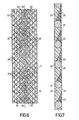
- FIGS 6 and 7 illustrate the structure of the matching layer.
- the layer is formed from a plastics elastomer mesh grid comprising strands 21 which is embedded in a plastics resin 24.
- the resin is loaded with high density metal particles.
- the loaded resin is cast around the mesh and the metal particles settle adjacent the mesh strands to provide an array of high density loaded regions 23 which are disposed in a two-dimensional quasiperiodic fashion within the layer.
- the grid of fibre strands controls the thickness of the matching layer.
- the width of the high density regions 23 is greatest along the central line 25 of the array and decreases as a function of the distance between the region and the central line of the array.
- the ratio of open area to fibre area in the mesh controls the distribution of the power.
- the metal particles tend to pile along the edges of the strands to form roughly triangular regions 23 which, in regions adjacent ⁇ he edges of the array, are separated from adjacent fibres by regions of unloaded resin 26.
- the acoustic impedance of the loaded resin regions 23 should be the geometric mean of the acoustic impedances of the transducer and of the test object.
- the acoustic impedance of the mesh fibres and of the unloaded regions 24 of the resin should be substantially lower than that of the loaded resin and may approach the impedance of the test object.
- the mesh is a nylon netting comprising perpendicular strands 21 which are knotted at the crossover points and define substantially square cells 22.
- Each strand of the net is formed from a twisted pair of .058 millimeter nylon threads.
- the sides of the individual cells are approximately 1.01 mm long.
- the mesh is approximately 0.152 mm thick before it is cast into the resin and expands to be approximately 0.178 mm thick after casting.
- the strands are oriented to form an angle of approximately 45 with the scanning axis of a transducer array.
- the matching layer is cast directly over the front silver electrode of the transducer.
- the silver electrode is first scrubbed with a fiberglass brush to remove any oxide surface layer.
- the electrode and mesh are degreased in an alcohol wash.
- the mesh is then placed on the electrode surface and is degassed in a vacuum chamber.
- a metal loaded epoxy resin is then poured uniformly along the center line of the surface of the mesh.
- the resin comprises Hobby Poxy Formula 2 manufactured by the Petite Paint Company, 36 Pine St., Rockaway, New Jersey.
- the resin is loaded with a 325 mesh tungsten powder in a ratio of 1.6 to 1.0 (tungsten to epoxy).
- the resin is then degassed under vacuum.
- a Mylar release sheet is placed over the surface of the resin layer and a flat glass sheet is clamped over the assembly. The resin is cured for 24 hours at 40°C.
- Fig. 7 is a sectional view of the cast layer taken parallel to one of the mesh strands.
- the settling action of the metal powder effectively segregates the material in the mesh cells into regions of substantially unloaded resin 24 having a relatively low acoustic impedance and regions of loaded resin 23 having a substantially higher acoustic impedance.
- the loaded regions are of substantially triangular cross-section and substantially fill the cells along the center line of the array. At the edges of the array the loaded regions may be separated from the two outside edges of the cell by an unloaded region 25.
- the resultant two-dimensional quasiperiodic structure of loaded resin has an approximately Gaussian frequency response characteristic and is ideally suited for matching transducer arrays in medical applications.
- the matching devices have been described herein with respect to preferred embodiments for use with a flat transducer array. Those skilled in the art will recognize, however, that the device is equally useful with curved transducer arrays and with single element transducers. Likewise, although a preferred embodiment has been described for use at 3.5 mHz; the structures are also efficient impedance matching devices at other frequencies used for medical imaging.
Landscapes
- Physics & Mathematics (AREA)
- Engineering & Computer Science (AREA)
- Acoustics & Sound (AREA)
- Multimedia (AREA)
- Transducers For Ultrasonic Waves (AREA)
- Ultra Sonic Daignosis Equipment (AREA)
- Investigating Or Analyzing Materials By The Use Of Ultrasonic Waves (AREA)
Applications Claiming Priority (2)
| Application Number | Priority Date | Filing Date | Title |
|---|---|---|---|
| US06/176,312 US4348904A (en) | 1980-08-08 | 1980-08-08 | Acoustic impedance matching device |
| US176312 | 1980-08-08 |
Publications (3)
| Publication Number | Publication Date |
|---|---|
| EP0045989A2 true EP0045989A2 (fr) | 1982-02-17 |
| EP0045989A3 EP0045989A3 (en) | 1982-12-01 |
| EP0045989B1 EP0045989B1 (fr) | 1984-09-26 |
Family
ID=22643855
Family Applications (1)
| Application Number | Title | Priority Date | Filing Date |
|---|---|---|---|
| EP81200834A Expired EP0045989B1 (fr) | 1980-08-08 | 1981-07-21 | Dispositif d'adaptation de l'impédance acoustique |
Country Status (7)
| Country | Link |
|---|---|
| US (1) | US4348904A (fr) |
| EP (1) | EP0045989B1 (fr) |
| JP (1) | JPS5920236B2 (fr) |
| AU (1) | AU540445B2 (fr) |
| CA (1) | CA1165858A (fr) |
| DE (1) | DE3166331D1 (fr) |
| ES (1) | ES8303780A1 (fr) |
Cited By (1)
| Publication number | Priority date | Publication date | Assignee | Title |
|---|---|---|---|---|
| GB2526566A (en) * | 2014-05-28 | 2015-12-02 | Skf Ab | Couplant and arrangement of couplant, transducer, and construction component |
Families Citing this family (17)
| Publication number | Priority date | Publication date | Assignee | Title |
|---|---|---|---|---|
| US5134988A (en) * | 1989-07-12 | 1992-08-04 | Diasonics, Inc. | Lens assembly for focusing energy |
| US5280722A (en) * | 1991-08-29 | 1994-01-25 | Madaras Eric I | Method and apparatus for indicating disbonds in joint regions |
| US5275167A (en) * | 1992-08-13 | 1994-01-04 | Advanced Technology Laboratories, Inc. | Acoustic transducer with tab connector |
| DE4327509A1 (de) * | 1993-08-16 | 1995-02-23 | Siemens Ag | Verfahren und Vorrichtung zur mechanischen Festigkeitsprüfung von Bauteilen |
| US5488957A (en) * | 1994-11-21 | 1996-02-06 | General Electric Company | System and method for promoting adhesion between lens and matching layer of ultrasonic transducer |
| US5638822A (en) * | 1995-06-30 | 1997-06-17 | Hewlett-Packard Company | Hybrid piezoelectric for ultrasonic probes |
| US5831492A (en) * | 1995-09-15 | 1998-11-03 | Sawtek Inc. | Weighted tapered spudt saw device |
| US5818310A (en) * | 1996-08-27 | 1998-10-06 | Sawtek Inc. | Series-block and line-width weighted saw filter device |
| JP3926448B2 (ja) * | 1997-12-01 | 2007-06-06 | 株式会社日立メディコ | 超音波探触子及びこれを用いた超音波診断装置 |
| US6371915B1 (en) | 1999-11-02 | 2002-04-16 | Scimed Life Systems, Inc. | One-twelfth wavelength impedence matching transformer |
| EP1396172A2 (fr) * | 2001-01-05 | 2004-03-10 | ANGELSEN, Bjorn A. J. | Transducteur a large bande |
| US7224104B2 (en) * | 2003-12-09 | 2007-05-29 | Kabushiki Kaisha Toshiba | Ultrasonic probe and ultrasonic diagnostic apparatus |
| JP4703372B2 (ja) * | 2005-11-04 | 2011-06-15 | 株式会社東芝 | 超音波プローブ及び超音波診断装置 |
| JP2007173320A (ja) * | 2005-12-19 | 2007-07-05 | Denso Corp | 積層型圧電素子及びその製造方法 |
| KR100837981B1 (ko) | 2006-10-17 | 2008-06-13 | 기아자동차주식회사 | 패널부재 파지용 지그장치 |
| US20090051250A1 (en) * | 2007-08-21 | 2009-02-26 | Dushyant Shah | Mesh Terminals For Piezoelectric Elements |
| US11793487B2 (en) * | 2017-01-26 | 2023-10-24 | Annamarie Saarinen | Transducer array device, method and system for cardiac conditions |
Family Cites Families (8)
| Publication number | Priority date | Publication date | Assignee | Title |
|---|---|---|---|---|
| US2922483A (en) * | 1954-06-03 | 1960-01-26 | Harris Transducer Corp | Acoustic or mechanical impedance |
| US3362501A (en) * | 1966-09-15 | 1968-01-09 | Magnaflux Corp | Acoustic transmission section |
| US3663842A (en) * | 1970-09-14 | 1972-05-16 | North American Rockwell | Elastomeric graded acoustic impedance coupling device |
| US3872332A (en) * | 1971-04-19 | 1975-03-18 | Honeywell Inc | Composite bond for acoustic transducers |
| US3971962A (en) * | 1972-09-21 | 1976-07-27 | Stanford Research Institute | Linear transducer array for ultrasonic image conversion |
| JPS5353393A (en) * | 1976-10-25 | 1978-05-15 | Matsushita Electric Ind Co Ltd | Ultrasonic probe |
| US4184094A (en) * | 1978-06-01 | 1980-01-15 | Advanced Diagnostic Research Corporation | Coupling for a focused ultrasonic transducer |
| US4326418A (en) * | 1980-04-07 | 1982-04-27 | North American Philips Corporation | Acoustic impedance matching device |
-
1980
- 1980-08-08 US US06/176,312 patent/US4348904A/en not_active Expired - Lifetime
-
1981
- 1981-07-21 DE DE8181200834T patent/DE3166331D1/de not_active Expired
- 1981-07-21 EP EP81200834A patent/EP0045989B1/fr not_active Expired
- 1981-08-06 AU AU73841/81A patent/AU540445B2/en not_active Ceased
- 1981-08-06 CA CA000383331A patent/CA1165858A/fr not_active Expired
- 1981-08-06 ES ES504590A patent/ES8303780A1/es not_active Expired
- 1981-08-07 JP JP56123172A patent/JPS5920236B2/ja not_active Expired
Cited By (2)
| Publication number | Priority date | Publication date | Assignee | Title |
|---|---|---|---|---|
| GB2526566A (en) * | 2014-05-28 | 2015-12-02 | Skf Ab | Couplant and arrangement of couplant, transducer, and construction component |
| US10598634B2 (en) | 2014-05-28 | 2020-03-24 | Aktiebolaget Skf | Couplant and arrangement of couplant, transducer, and construction component |
Also Published As
| Publication number | Publication date |
|---|---|
| JPS5920236B2 (ja) | 1984-05-11 |
| ES504590A0 (es) | 1983-02-01 |
| ES8303780A1 (es) | 1983-02-01 |
| CA1165858A (fr) | 1984-04-17 |
| AU7384181A (en) | 1982-02-11 |
| EP0045989A3 (en) | 1982-12-01 |
| AU540445B2 (en) | 1984-11-15 |
| DE3166331D1 (en) | 1984-10-31 |
| JPS5760794A (en) | 1982-04-12 |
| EP0045989B1 (fr) | 1984-09-26 |
| US4348904A (en) | 1982-09-14 |
Similar Documents
| Publication | Publication Date | Title |
|---|---|---|
| EP0045989B1 (fr) | Dispositif d'adaptation de l'impédance acoustique | |
| US6467140B2 (en) | Method of making composite piezoelectric transducer arrays | |
| US6104126A (en) | Composite transducer with connective backing block | |
| Smith | The role of piezocomposites in ultrasonic transducers | |
| EP0355694B1 (fr) | Transducteur composite piézoélectrique pour utilisation dans une sonde ultrasonore | |
| US6868594B2 (en) | Method for making a transducer | |
| US4658176A (en) | Ultrasonic transducer using piezoelectric composite | |
| US6666825B2 (en) | Ultrasound transducer for improving resolution in imaging system | |
| US4326418A (en) | Acoustic impedance matching device | |
| US6183578B1 (en) | Method for manufacture of high frequency ultrasound transducers | |
| JPH0239251B2 (fr) | ||
| US20040032188A1 (en) | Piezoelectric transducer with gas matrix | |
| EP1050079B1 (fr) | Materiau piezocomposite haute sensibilite et transducteur ultrasonore a base de ce materiau | |
| JP2001025094A (ja) | 1−3複合圧電体 | |
| Mills et al. | Combining multi-layers and composites to increase SNR for medical ultrasound transducers | |
| Takeuchi et al. | Medical ultrasonic probe using electrostrictive-ceramics/polymer composite | |
| JP4320098B2 (ja) | アレイ型複合圧電体 | |
| JP2601503B2 (ja) | アレイ型超音波探触子 | |
| Cannata et al. | A 35 MHz linear array for medical imaging | |
| Snook et al. | Design of a high frequency annular array for medical ultrasound | |
| JPS62261300A (ja) | 超音波探触子用複合圧電材 | |
| JPH07108037B2 (ja) | 超音波探触子 | |
| Seyed-Bolorforosh | Integrated impedance matching layer | |
| JPH0546217B2 (fr) | ||
| Cannata et al. | Development of a high frequency (> 20 MHz) linear ultrasonic array using fine grain ceramic elements |
Legal Events
| Date | Code | Title | Description |
|---|---|---|---|
| PUAI | Public reference made under article 153(3) epc to a published international application that has entered the european phase |
Free format text: ORIGINAL CODE: 0009012 |
|
| AK | Designated contracting states |
Designated state(s): BE DE FR GB SE |
|
| PUAL | Search report despatched |
Free format text: ORIGINAL CODE: 0009013 |
|
| AK | Designated contracting states |
Designated state(s): BE DE FR GB SE |
|
| 17P | Request for examination filed |
Effective date: 19821110 |
|
| GRAA | (expected) grant |
Free format text: ORIGINAL CODE: 0009210 |
|
| AK | Designated contracting states |
Designated state(s): BE DE FR GB SE |
|
| REF | Corresponds to: |
Ref document number: 3166331 Country of ref document: DE Date of ref document: 19841031 |
|
| ET | Fr: translation filed | ||
| PLBE | No opposition filed within time limit |
Free format text: ORIGINAL CODE: 0009261 |
|
| STAA | Information on the status of an ep patent application or granted ep patent |
Free format text: STATUS: NO OPPOSITION FILED WITHIN TIME LIMIT |
|
| 26N | No opposition filed | ||
| GBPC | Gb: european patent ceased through non-payment of renewal fee | ||
| PG25 | Lapsed in a contracting state [announced via postgrant information from national office to epo] |
Ref country code: SE Effective date: 19880722 |
|
| PG25 | Lapsed in a contracting state [announced via postgrant information from national office to epo] |
Ref country code: BE Effective date: 19880731 |
|
| BERE | Be: lapsed |
Owner name: NORTH AMERICAN PHILIPS CORP. Effective date: 19880731 |
|
| REG | Reference to a national code |
Ref country code: FR Ref legal event code: CD |
|
| PGFP | Annual fee paid to national office [announced via postgrant information from national office to epo] |
Ref country code: FR Payment date: 19940727 Year of fee payment: 14 |
|
| PGFP | Annual fee paid to national office [announced via postgrant information from national office to epo] |
Ref country code: GB Payment date: 19941206 Year of fee payment: 14 |
|
| EUG | Se: european patent has lapsed |
Ref document number: 81200834.0 Effective date: 19890510 |
|
| PG25 | Lapsed in a contracting state [announced via postgrant information from national office to epo] |
Ref country code: GB Effective date: 19950721 |
|
| GBPC | Gb: european patent ceased through non-payment of renewal fee |
Effective date: 19950721 |
|
| PG25 | Lapsed in a contracting state [announced via postgrant information from national office to epo] |
Ref country code: FR Effective date: 19960430 |
|
| REG | Reference to a national code |
Ref country code: FR Ref legal event code: ST |
|
| REG | Reference to a national code |
Ref country code: FR Ref legal event code: ST |
|
| REG | Reference to a national code |
Ref country code: FR Ref legal event code: ST |
|
| PGFP | Annual fee paid to national office [announced via postgrant information from national office to epo] |
Ref country code: DE Payment date: 19960924 Year of fee payment: 16 |
|
| PG25 | Lapsed in a contracting state [announced via postgrant information from national office to epo] |
Ref country code: DE Free format text: LAPSE BECAUSE OF NON-PAYMENT OF DUE FEES Effective date: 19980401 |