EP0046006B1 - Elektromagnetischer Messwandler - Google Patents
Elektromagnetischer Messwandler Download PDFInfo
- Publication number
- EP0046006B1 EP0046006B1 EP81302959A EP81302959A EP0046006B1 EP 0046006 B1 EP0046006 B1 EP 0046006B1 EP 81302959 A EP81302959 A EP 81302959A EP 81302959 A EP81302959 A EP 81302959A EP 0046006 B1 EP0046006 B1 EP 0046006B1
- Authority
- EP
- European Patent Office
- Prior art keywords
- output
- integrator
- transducer
- circuit
- winding
- Prior art date
- Legal status (The legal status is an assumption and is not a legal conclusion. Google has not performed a legal analysis and makes no representation as to the accuracy of the status listed.)
- Expired
Links
- 238000004804 winding Methods 0.000 claims description 18
- 230000004907 flux Effects 0.000 claims description 3
- 239000000696 magnetic material Substances 0.000 claims description 3
- 230000004044 response Effects 0.000 claims description 3
- 230000001419 dependent effect Effects 0.000 claims description 2
- 239000003990 capacitor Substances 0.000 description 6
- 229910001209 Low-carbon steel Inorganic materials 0.000 description 3
- 238000010586 diagram Methods 0.000 description 2
- 238000006073 displacement reaction Methods 0.000 description 2
- 230000000694 effects Effects 0.000 description 2
- 238000012935 Averaging Methods 0.000 description 1
- 229910000828 alnico Inorganic materials 0.000 description 1
- 230000008901 benefit Effects 0.000 description 1
- 230000008859 change Effects 0.000 description 1
- 238000010276 construction Methods 0.000 description 1
- 230000007423 decrease Effects 0.000 description 1
- 238000001514 detection method Methods 0.000 description 1
- 230000036039 immunity Effects 0.000 description 1
- 230000002401 inhibitory effect Effects 0.000 description 1
- 230000010354 integration Effects 0.000 description 1
- 230000007704 transition Effects 0.000 description 1
Images
Classifications
-
- G—PHYSICS
- G01—MEASURING; TESTING
- G01D—MEASURING NOT SPECIALLY ADAPTED FOR A SPECIFIC VARIABLE; ARRANGEMENTS FOR MEASURING TWO OR MORE VARIABLES NOT COVERED IN A SINGLE OTHER SUBCLASS; TARIFF METERING APPARATUS; MEASURING OR TESTING NOT OTHERWISE PROVIDED FOR
- G01D5/00—Mechanical means for transferring the output of a sensing member; Means for converting the output of a sensing member to another variable where the form or nature of the sensing member does not constrain the means for converting; Transducers not specially adapted for a specific variable
- G01D5/12—Mechanical means for transferring the output of a sensing member; Means for converting the output of a sensing member to another variable where the form or nature of the sensing member does not constrain the means for converting; Transducers not specially adapted for a specific variable using electric or magnetic means
- G01D5/14—Mechanical means for transferring the output of a sensing member; Means for converting the output of a sensing member to another variable where the form or nature of the sensing member does not constrain the means for converting; Transducers not specially adapted for a specific variable using electric or magnetic means influencing the magnitude of a current or voltage
- G01D5/20—Mechanical means for transferring the output of a sensing member; Means for converting the output of a sensing member to another variable where the form or nature of the sensing member does not constrain the means for converting; Transducers not specially adapted for a specific variable using electric or magnetic means influencing the magnitude of a current or voltage by varying inductance, e.g. by a movable armature
- G01D5/2006—Mechanical means for transferring the output of a sensing member; Means for converting the output of a sensing member to another variable where the form or nature of the sensing member does not constrain the means for converting; Transducers not specially adapted for a specific variable using electric or magnetic means influencing the magnitude of a current or voltage by varying inductance, e.g. by a movable armature by influencing the self-induction of one or more coils
- G01D5/2013—Mechanical means for transferring the output of a sensing member; Means for converting the output of a sensing member to another variable where the form or nature of the sensing member does not constrain the means for converting; Transducers not specially adapted for a specific variable using electric or magnetic means influencing the magnitude of a current or voltage by varying inductance, e.g. by a movable armature by influencing the self-induction of one or more coils by a movable ferromagnetic element, e.g. a core
Definitions
- This invention relates to an electromagnetic transducer of the kind known as a variable reluctance transducer comprising a source of magnetic flux and a pick-up winding linked with said source so as to produce electrical output signals in response to the movement of a relatively movable member of magnetic material adjacent said source.
- the edge of periphery of the relatively movable member is shaped (with teeth or otherwise) so that the reluctance of the magnetic circuit changes according to whether or not an air gap therein is bridged (or partially bridged) by a tooth or other projecting portion of the relatively movable member.
- the arrangement permits accurate detection of zero crossings in one direction only.
- the first mentioned comparator has as its reference voltage a signal derived from a peak store.
- This comparator detects when the integrator output in any integration period is greater than that in the previous period. Again zero-crossings in one direction only are detected and the comparator which operates from the integrator output is not intended to provide accurate positional information but only to indicate whether the next zero-crossing follows a high output from the integrator.
- a transducer in accordance with the invention comprises a source of magnetic flux, a pick-up winding magnetically linked with said source so as to produce electrical output signals in response to the movement of a relatively movable shaped member of magnetic material in a magnetic circuit including said source, and a discriminating circuit connected to said winding and comprising an active integrating circuit providing a continuous output dependent on the time integral of the winding signals, and a voltage comparator connected to compare the output of the integrator with a reference voltage level, characterised by a bias circuit sensitive to the output of the integrator and connected to supply a variable bias current to the input of the integrator which causes the integrator output to be varied so as to control the relationship between positive and negative peak excursions of the integrator output and said reference voltage level.
- Embodiments of the invention are defined in Claims 2 to 7.
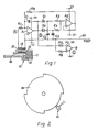
- the transducer 10 comprises a C-shaped assembly made up of a permanent magnet 11 formed of Alnico V and two mild steel plates 12, 13 attached to opposite ends of the magnet and forming the limbs of the C.
- the plate 13 is longer than the plate 12 and carries a pick-up winding 14 on a suitable spool 15, the end of the plate 13 being joggled to retain the spool.
- the two limbs of the C lie on opposite sides of the plate of a rotatable mild steel disc 16 so that the C lies in a plane substantially perpendicular to the direction of movement of the disc 16 relative to the transducer.
- the edge of the disc is cut away to provide four quadrants, an opposite pair of which are of larger radius than the other pair.
- the difference in radius is such that the edges of the larger quadrants can lie in the air gap between the limbs of the C, whereas the smaller quadrants do not reach the longer limb formed by plate 13.
- the winding 14 produces pulses of alternately opposite polarity as the disc rotates, i.e. a pulse of one polarity as the marginal edge of each larger quadrant passes into the gap in the C and an opposite polarity pulse as the marginal edge passes out again.
- the peak voltage of these pulses increases as the speed increases, but the duration of the pulses decreases.
- the winding 14 of the transducer is connected at one end of a reference voltage rail 20 and at the other end by a resistor R1 to the inverting input of an operational amplifier A1 having a capacitor C1 connected between its output and inverting input terminals, and its non-inverting input connected to the rail 20, so that it operates as an active integrator.
- the output terminal of the amplifier A1 is connected to the anode and cathode respectively of two diodes D1 and D2 forming, in combination with two capacitors C2 and C3 connected between the other terminals of these diodes and the rail 20, positive and negative peak detector circuits.
- resistors R2 and R3 are connected in series between the cathode of diode D1 and the anode of diode D2, the junction of these resistors being connected to the non-inverting input of an operational amplifier A2 connected as a voltage follower and having its output terminal connected by a resistor R4 to the inverting input of the amplifier A1.
- a voltage comparator A3 has one input connected by a resistor R5 to the output of the amplifier A1 and its other input connected by a resistor R6 to the rail 20.
- the effect of the peak detectors, the resistors R2 and R3 the amplifier A2 and the resistor R4 is to apply to the inverting input of the integrator amplifier A1 a variable bias current such that the magnitudes of the opposite peaks of the integrator output are maintained in the same, i.e. the integrator output is kept symmetrical with respect to the reference voltage.
- the output of the integrator is approximately constant so that the timing of the "zero-crossings" detected by the comparator A3 remains constant.
- the variable bias referred to ensures that these zero crossings always occur at fixed positions of the disc 16 irrespective of its speed.
- the use a C-shaped assembly for the transducer, with the limbs of the C on opposite sides of the disc 16 provides the advantage over conventional transducers, where the gap in the core of the transducer faces one side of or the edge of the disc, that the effects of disc bearing wear causing axial displacement, eccentricity or inclination of the disc are cancelled out.
- the difference in length of the limbs of the C ensures that there are large changes in the reluctance of the magnetic circuit.
- the size of the transducer 10 is small in relation to the diameter of the disc 16. This ensures that the pulses from the winding 14 are short compared with the spaces between them, assisting in providing great accuracy in detecting when the disc passes through its specific positions.
- variable biasing means utilizes two peak detectors.
- an averaging circuit could be employed.
- the time constants of the integrator should be long (e.g. twice as long) compared with the maximum period between transitions.
- the relatively movable member is a disc which would, in use be attached to a rotating member, the rotation of which is to be detected for example the shaft of an engine, when the transducer is used in an ignition timing system.
- the invention could however, equally be applied to a linear displacement, in which case the movable member would be a mild steel strip with teeth projecting into the air gap.
- the circuit may also include means for inhibiting the output if the opposite peak values are not within a preset tolerance. This would operate at start up and prevent inaccurately time outputs being produced.
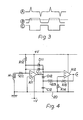
- an operational amplifier A11 has its non-inverting input connected to a ground rail 22 and its inverting input connected by a resistor R11 and the winding 14 in series to the ground rail and also by a capacitor C11 to its output terminal.
- a bias resistor R12 connects the inverting input of amplifier A11 to a positive supply rail and a diode D11 has its anode connected to the inverting input and its cathode connected to the output terminal of the amplifier A11.
- resistor R12 is significantly higher than that of resistor R11 and is chosen so as to provide a sufficient current into the "virtual earth" at the inverting input amplifier to overcome the input bias current of the amplifier and thereby to cause the output of amplifier A11 to drift negatively.
- the diode D11 limits this negative drift so that the output of amplifier A11 cannot fall significantly below earth rail level.
- the output of amplifier A11 is connected to a peak-hold circuit consisting of a diode D12 and a capacitor C12, the diode D12 having its anode connected to the output of amplifier A11 and its cathode connected by the capacitor C12 to the earth rail 20.
- Two resistors R13 and R14 are connected in series across the capacitor C12 and their common point is connected to the non-inverting input of an operational amplifier A12 connected as a voltage comparator.
- the output of amplifier A11 is connected to the inverting input of amplifier A12 and a feedbck resistor R15 is connected between the output and the non-inverting input of amplifier A12 to provide a relatively small amount of positive feedback to ensure clean switching of the amplifier A12 between its two output states.
- resistors R13 and R14 are chosen so that the reference voltage at their common point coincides with the voltage at the output of amplifier A11 when the peaks in the pulses from the winding 14 occur. If these pulses are symmetrical, then the output of amplifier All will be at half of its peak value when the pulse peaks occur. The resistors R13 and R14 should then be of equal value. If however, the pulses are assym- metrical, e.g. if the time taken for the pulse voltage to reach its peak is longer than that taken for the voltage to fall back to zero (which could occur with certain designs of transducer), then the amplifier A11 output at the instant of the pulse peak will be more than half its peak value. In this case resistor R14 will be chosen to have a higher ohmic value than resistor R13.
- amplifier A11 could be of the type which uses a simple single rail and earth return type of supply. In this case the diode D11 could be omitted because the construction of the amplifier is such that its output cannot fall below the earth rail voltage. Limitation of the output of amplifier A11 is then effected by saturation of the amplifier A11 output stage.
Landscapes
- Physics & Mathematics (AREA)
- General Physics & Mathematics (AREA)
- Measurement Of Length, Angles, Or The Like Using Electric Or Magnetic Means (AREA)
- Transmission And Conversion Of Sensor Element Output (AREA)
- Switches That Are Operated By Magnetic Or Electric Fields (AREA)
Claims (7)
Applications Claiming Priority (2)
| Application Number | Priority Date | Filing Date | Title |
|---|---|---|---|
| GB8023676 | 1980-07-19 | ||
| GB8023676 | 1980-07-19 |
Publications (3)
| Publication Number | Publication Date |
|---|---|
| EP0046006A2 EP0046006A2 (de) | 1982-02-17 |
| EP0046006A3 EP0046006A3 (en) | 1983-01-05 |
| EP0046006B1 true EP0046006B1 (de) | 1986-04-16 |
Family
ID=10514900
Family Applications (1)
| Application Number | Title | Priority Date | Filing Date |
|---|---|---|---|
| EP81302959A Expired EP0046006B1 (de) | 1980-07-19 | 1981-06-30 | Elektromagnetischer Messwandler |
Country Status (5)
| Country | Link |
|---|---|
| US (1) | US4424550A (de) |
| EP (1) | EP0046006B1 (de) |
| JP (1) | JPS5750608A (de) |
| DE (1) | DE3174392D1 (de) |
| ES (1) | ES504067A0 (de) |
Cited By (4)
| Publication number | Priority date | Publication date | Assignee | Title |
|---|---|---|---|---|
| DE4131128C1 (de) * | 1991-09-19 | 1993-02-25 | Daimler-Benz Aktiengesellschaft, 7000 Stuttgart, De | |
| DE4407565A1 (de) * | 1993-03-11 | 1994-09-15 | Fujitsu Ltd | Ein Magnetsensor und eine elektronische Schaltung dafür |
| DE4434978A1 (de) * | 1994-09-30 | 1996-04-04 | Teves Gmbh Alfred | Aktiver Bewegungssensor |
| DE4434977A1 (de) * | 1994-09-30 | 1996-04-04 | Teves Gmbh Alfred | Aktiver Bewegungssensor |
Families Citing this family (7)
| Publication number | Priority date | Publication date | Assignee | Title |
|---|---|---|---|---|
| DE3517509C2 (de) * | 1985-05-15 | 1997-08-07 | Bosch Gmbh Robert | Meßeinrichtung an einem Kraftfahrzeug zum Erfassen von Betriebskenngrößen |
| FR2611894A1 (fr) * | 1987-02-26 | 1988-09-09 | Thomson Semiconducteurs | Dispositif electronique de mesure d'angle |
| DE3708210A1 (de) * | 1987-03-13 | 1988-09-22 | Bosch Gmbh Robert | Schaltungsanordnung zur auswertung der signale eines induktiven messwertaufnehmers |
| DE4220596C1 (de) * | 1992-06-24 | 1993-12-09 | Mfp Mestechnik Und Fertigungst | Schaltungsanordnung zur Bestimmung des Übertragungsmaßes einer variablen Übertragungsschaltung |
| GB2310496A (en) * | 1996-02-21 | 1997-08-27 | De La Rue Syst | Method and apparatus for authenticating documents |
| US10734877B2 (en) | 2014-06-10 | 2020-08-04 | The Regents Of The Unversity Of Michigan | Electromagnetic energy transducer |
| WO2015191047A1 (en) | 2014-06-10 | 2015-12-17 | The Regents Of The University Of Michigan | Mechanical amplifier for energy harvester |
Family Cites Families (12)
| Publication number | Priority date | Publication date | Assignee | Title |
|---|---|---|---|---|
| DE1216019B (de) * | 1962-09-18 | 1966-05-05 | Philips Patentverwaltung | Vorrichtung zur drehzahlabhaengigen Zuend-zeitpunktverstellung bei Brennkraftmaschinen |
| DE1539251A1 (de) * | 1966-09-29 | 1969-12-04 | Siemens Ag | Zuendgeraet fuer Verbrennungsmotoren |
| JPS5427742B2 (de) * | 1973-07-16 | 1979-09-12 | ||
| GB1486891A (en) * | 1973-09-28 | 1977-09-28 | Lucas Electrical Ltd | Spark ignition systems for internal combustion engines |
| GB1514735A (en) * | 1974-05-21 | 1978-06-21 | Lucas Electrical Ltd | Angular position transducer for use in engine timing controls |
| US4153850A (en) * | 1977-06-17 | 1979-05-08 | General Motors Corporation | Circuit for producing a series of substantially square wave output signals |
| JPS5486362A (en) * | 1977-12-21 | 1979-07-09 | Matsushita Electric Ind Co Ltd | Rotating angle detector |
| JPS5487549A (en) * | 1977-12-23 | 1979-07-12 | Matsushita Electric Ind Co Ltd | Rotating angle detector |
| JPS5489657A (en) * | 1977-12-26 | 1979-07-16 | Matsushita Electric Ind Co Ltd | Rotating angle detector |
| JPS6027363B2 (ja) | 1978-03-01 | 1985-06-28 | 株式会社日立製作所 | 回転角度検出装置 |
| DE2827799A1 (de) | 1978-06-24 | 1980-01-10 | Bosch Gmbh Robert | Schaltungsanordnung zum erfassen eines signales eines bezugsmarkengebers |
| GB2028511A (en) * | 1978-08-19 | 1980-03-05 | Gunton Electronics Ltd | Indicating stages of an operating cycle |
-
1981
- 1981-06-30 EP EP81302959A patent/EP0046006B1/de not_active Expired
- 1981-06-30 DE DE8181302959T patent/DE3174392D1/de not_active Expired
- 1981-07-06 US US06/280,526 patent/US4424550A/en not_active Expired - Fee Related
- 1981-07-17 ES ES504067A patent/ES504067A0/es active Granted
- 1981-07-20 JP JP56113437A patent/JPS5750608A/ja active Granted
Cited By (6)
| Publication number | Priority date | Publication date | Assignee | Title |
|---|---|---|---|---|
| DE4131128C1 (de) * | 1991-09-19 | 1993-02-25 | Daimler-Benz Aktiengesellschaft, 7000 Stuttgart, De | |
| DE4407565A1 (de) * | 1993-03-11 | 1994-09-15 | Fujitsu Ltd | Ein Magnetsensor und eine elektronische Schaltung dafür |
| DE4434978A1 (de) * | 1994-09-30 | 1996-04-04 | Teves Gmbh Alfred | Aktiver Bewegungssensor |
| DE4434977A1 (de) * | 1994-09-30 | 1996-04-04 | Teves Gmbh Alfred | Aktiver Bewegungssensor |
| DE4434977B4 (de) * | 1994-09-30 | 2005-02-17 | Continental Teves Ag & Co. Ohg | Aktiver Bewegungssensor |
| DE4434978B4 (de) * | 1994-09-30 | 2007-08-23 | Continental Teves Ag & Co. Ohg | Aktiver Bewegungssensor |
Also Published As
| Publication number | Publication date |
|---|---|
| EP0046006A2 (de) | 1982-02-17 |
| JPS5750608A (en) | 1982-03-25 |
| US4424550A (en) | 1984-01-03 |
| DE3174392D1 (en) | 1986-05-22 |
| EP0046006A3 (en) | 1983-01-05 |
| ES8204903A1 (es) | 1982-05-16 |
| JPH0419491B2 (de) | 1992-03-30 |
| ES504067A0 (es) | 1982-05-16 |
Similar Documents
| Publication | Publication Date | Title |
|---|---|---|
| US5729130A (en) | Tracking and holding in a DAC the peaks in the field-proportional voltage in a slope activated magnetic field sensor | |
| JPS5924970Y2 (ja) | 回転位置検出装置 | |
| EP0359422B1 (de) | Induktiver Geschwindigkeitssensor | |
| US4367721A (en) | Signal detection circuit with self-adjusting threshold having modulated carrier input | |
| US3967200A (en) | Speed detector for use with miniature DC motor | |
| US4424550A (en) | Electromagnetic transducer | |
| JPS59185665U (ja) | デジタルパルス発生システム | |
| KR880001721B1 (ko) | 위치 검출 신호 발생기 | |
| US6459261B1 (en) | Magnetic incremental motion detection system and method | |
| US4609869A (en) | Magnetic sensor and circuit for detecting the edge of a target as it passes the centerline of the sensor | |
| JPH0350965B2 (de) | ||
| JPH0432970B2 (de) | ||
| JPH074987A (ja) | 基準位置検出装置 | |
| JPH0421066Y2 (de) | ||
| JPS60262061A (ja) | 信号の零点通過検出回路 | |
| HU177461B (en) | Sensing device for speed of wheel | |
| EP0058498B1 (de) | Positionsübertrager | |
| JP2546233B2 (ja) | 磁気エンコ−ダ用磁気ヘツドの原点検出部 | |
| JPH0140930B2 (de) | ||
| JPH0690046B2 (ja) | 変位検出装置 | |
| JPH0136337B2 (de) | ||
| JPH081387B2 (ja) | 磁気センサ | |
| GB2334636A (en) | Dynamic range control for a threshold detector | |
| JP2630590B2 (ja) | 磁気エンコーダの零点検出装置 | |
| JP2546282B2 (ja) | 磁気エンコ−ダ用磁気ヘッドの原点検出部 |
Legal Events
| Date | Code | Title | Description |
|---|---|---|---|
| PUAI | Public reference made under article 153(3) epc to a published international application that has entered the european phase |
Free format text: ORIGINAL CODE: 0009012 |
|
| AK | Designated contracting states |
Designated state(s): DE FR GB IT |
|
| RAP1 | Party data changed (applicant data changed or rights of an application transferred) |
Owner name: LUCAS INDUSTRIES PLC |
|
| PUAL | Search report despatched |
Free format text: ORIGINAL CODE: 0009013 |
|
| AK | Designated contracting states |
Designated state(s): DE FR GB IT |
|
| 17P | Request for examination filed |
Effective date: 19830524 |
|
| GRAA | (expected) grant |
Free format text: ORIGINAL CODE: 0009210 |
|
| ITF | It: translation for a ep patent filed | ||
| AK | Designated contracting states |
Kind code of ref document: B1 Designated state(s): DE FR GB IT |
|
| ET | Fr: translation filed | ||
| REF | Corresponds to: |
Ref document number: 3174392 Country of ref document: DE Date of ref document: 19860522 |
|
| PLBI | Opposition filed |
Free format text: ORIGINAL CODE: 0009260 |
|
| 26 | Opposition filed |
Opponent name: ROBERT BOSCH GMBH Effective date: 19870116 |
|
| PLBN | Opposition rejected |
Free format text: ORIGINAL CODE: 0009273 |
|
| STAA | Information on the status of an ep patent application or granted ep patent |
Free format text: STATUS: OPPOSITION REJECTED |
|
| 27O | Opposition rejected |
Effective date: 19890821 |
|
| ITTA | It: last paid annual fee | ||
| PGFP | Annual fee paid to national office [announced via postgrant information from national office to epo] |
Ref country code: FR Payment date: 19930609 Year of fee payment: 13 |
|
| PGFP | Annual fee paid to national office [announced via postgrant information from national office to epo] |
Ref country code: GB Payment date: 19930618 Year of fee payment: 13 |
|
| PGFP | Annual fee paid to national office [announced via postgrant information from national office to epo] |
Ref country code: DE Payment date: 19930630 Year of fee payment: 13 |
|
| PG25 | Lapsed in a contracting state [announced via postgrant information from national office to epo] |
Ref country code: GB Effective date: 19940630 |
|
| PG25 | Lapsed in a contracting state [announced via postgrant information from national office to epo] |
Ref country code: FR Effective date: 19950228 |
|
| GBPC | Gb: european patent ceased through non-payment of renewal fee |
Effective date: 19940630 |
|
| PG25 | Lapsed in a contracting state [announced via postgrant information from national office to epo] |
Ref country code: DE Effective date: 19950301 |
|
| REG | Reference to a national code |
Ref country code: FR Ref legal event code: ST |