EP0046041A1 - Valve de contrôle pour fluide - Google Patents
Valve de contrôle pour fluide Download PDFInfo
- Publication number
- EP0046041A1 EP0046041A1 EP81303523A EP81303523A EP0046041A1 EP 0046041 A1 EP0046041 A1 EP 0046041A1 EP 81303523 A EP81303523 A EP 81303523A EP 81303523 A EP81303523 A EP 81303523A EP 0046041 A1 EP0046041 A1 EP 0046041A1
- Authority
- EP
- European Patent Office
- Prior art keywords
- spindle
- valve
- plunger
- ring
- valve member
- Prior art date
- Legal status (The legal status is an assumption and is not a legal conclusion. Google has not performed a legal analysis and makes no representation as to the accuracy of the status listed.)
- Withdrawn
Links
- 239000012530 fluid Substances 0.000 title description 11
- 238000007789 sealing Methods 0.000 claims abstract description 23
- 230000000694 effects Effects 0.000 claims abstract description 5
- 210000004907 gland Anatomy 0.000 abstract description 2
- 239000000463 material Substances 0.000 description 4
- 239000004033 plastic Substances 0.000 description 4
- 229920003023 plastic Polymers 0.000 description 4
- 230000006835 compression Effects 0.000 description 2
- 238000007906 compression Methods 0.000 description 2
- 239000004519 grease Substances 0.000 description 2
- 239000002184 metal Substances 0.000 description 2
- 239000005060 rubber Substances 0.000 description 2
- 239000000126 substance Substances 0.000 description 2
- XLYOFNOQVPJJNP-UHFFFAOYSA-N water Substances O XLYOFNOQVPJJNP-UHFFFAOYSA-N 0.000 description 2
- 229920001875 Ebonite Polymers 0.000 description 1
- 230000007797 corrosion Effects 0.000 description 1
- 238000005260 corrosion Methods 0.000 description 1
- NBVXSUQYWXRMNV-UHFFFAOYSA-N fluoromethane Chemical compound FC NBVXSUQYWXRMNV-UHFFFAOYSA-N 0.000 description 1
- 239000010985 leather Substances 0.000 description 1
- 239000007788 liquid Substances 0.000 description 1
- 238000012856 packing Methods 0.000 description 1
- 239000004810 polytetrafluoroethylene Substances 0.000 description 1
- 229920001343 polytetrafluoroethylene Polymers 0.000 description 1
- 239000003566 sealing material Substances 0.000 description 1
Images



Classifications
-
- F—MECHANICAL ENGINEERING; LIGHTING; HEATING; WEAPONS; BLASTING
- F16—ENGINEERING ELEMENTS AND UNITS; GENERAL MEASURES FOR PRODUCING AND MAINTAINING EFFECTIVE FUNCTIONING OF MACHINES OR INSTALLATIONS; THERMAL INSULATION IN GENERAL
- F16K—VALVES; TAPS; COCKS; ACTUATING-FLOATS; DEVICES FOR VENTING OR AERATING
- F16K41/00—Spindle sealings
- F16K41/02—Spindle sealings with stuffing-box ; Sealing rings
Definitions
- This invention relates to a fluid control valve comprising a moveable valve member within a housing, the valve member being provided with a secondary seal usually in the form of a packing ring, 0 ring, or washer which may create a seal between the valve body wall and the moveable valve member.
- the invention is applicable to many types of valves such as radiator valves, stop-cocks, hot and cold water taps, gas and liquid control valves and any other valves where fluids have to be controlled.
- An object of the invention is to provide a moveable valve member with an adjustable secondary seal so that any slight wear and tear, which inevitably happens after a comparatively short period of time in use, can be taken up by the adjuster thereby eliminating the need to replace the secondary seal.
- a moveable valve member, spindle or plunger is provided with a resilient sealing-washer or 0 ring which is trapped between two relatively moveable parts of the valve member or plunger, means being provided to enable the pressure applied to the trapped 0 ring or washer to be varied whereby the effectiveness of the seal may be varied.
- the secondary seal may be improved by adjusting the pressure applied to the 0 ring or other sealing washer and thus improving the sealing qualities.
- the invention consists in a valve comprising a housing and a valve member, spindle or plunger axially moveable within the housing, the valve member, spindle or plunger having at one end means to open and close the valve, and a secondary seal disposed between the valve member, spindle or plunger and the wall of the housing, the secondary seal comprising a resilient washer or sealing ring or the like trapped between two parts of the valve member, spindle or plunger and adapted to make sealing contact with the wall of the valve, means being provided for adjusting the relative positions of the two parts of the-valve member, spindle or plunger so as to vary the sealing pressure exerted by the secondary seal on the wall of the housing.
- the-two parts of the valve member, spindle or plunger each have an axial bore
- the means for adjusting the pressure applied to seal by the two parts of the spindle consists of a threaded member which extends through the bore in one part of the spindle into a threaded portion of the bore in the other part of the spindle whereby rotation of the threaded member will vary the pressure exerted on the seal.
- the threaded member is in the form of a bolt, a nut and bolt or a screw which may be adjusted by means of a tool inserted through the upper opening of the valve.
- the lower end of the valve member effects the primary seal by means of a resilient washer attached to a washer plate of plastics material or metal or other suitable material which engages loosely over a projection or flange on the lower portion of the valve member or spindle.
- valves may be adapted in accordance with the invention by use of an adaptor or bush.
- the adaptor or bush includes a valve member, spindle or plunger corresponding in dimensions externally to the valve member it is to replace, the valve being modified in accordance with this invention so as to receive the adjustable secondary seal referred to above.
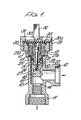
- a radiator valve which has a valve body 10 having a flanged inlet fitting 11, a flanged outlet fitting 12, and a threaded aperture-13 into which the working parts of the valve can be fitted.
- the valve body provides a main valve seat 14 adapted to be closed by a-corresponding seating 15 on a valve plunger 16.
- the valve spindle is divided into two portions, an upper spindle 17 and a lower spindle 18 which forms part of the valve plunger 16.
- On the upper spindle is a flange 19 corresponding to a similar flange 20 on the lower spindle 18.
- the upper spindle includes a downwardly projecting stub shaft 21 which has flats 22 on its sides adapted to mate with corresponding flat surfaces 23 formed in a bore 24 in the upper end of the lower spindle 18.
- a secondary or O ring seal 25 which may alternatively be a washer, or ring washer, is arranged to be trapped between the flange 19 and the flange 20.
- a screw or bolt 26 is provided which passes through a bore in the upper spindle 17 and engages a threaded bore 27 (see Figure 1) in the lower spindle 18. By tightening up the screw or bolt 26, the 0 ring seal 25 will be compressed between flanges 19 and 20 and the tightness of the screw or bolt 26 will determine the pressure exerted on the O ring seal 25 and hence the sealing effect of the secondary seal.
- the upper spindle 17 is supported by. a collar 27a into which it can be screwed, there being a collar sealing washer 28 between the collar 27a and the top flat face of the flange 19 of upper spindle 17.
- the collar 27a has an external thread 27b which may engage in the corresponding thread 13 in the aperture of upper end of the--valve body 10, the collar 27a being held in position, as shown in Figure 1, by a circlip 35.
- valve body 29 which engages an external thread 30 on the valve body, a cap sealing washer 30a being interposed between the cap 29 and the upper face portion 31 of the valve body.
- cap 29 includes a key 32 so that when the cap is removed the key 32 can be engaged in a corresponding square aperture 33 in the upper spindle 17 so as to turn the spindle and thereby apply the main valve by causing plunger 16 to seat on the valve seat 14.
- the screw 26 is then inserted to hold the upper spindle 17, O ring seal 25 and lower spindle 18 together and rotated until the spindle parts are held closely together with- the O ring seal 25 trapped between them.
- the collar sealing washer 28 is then placed over the-flange 19 and the collar 27a is threaded onto the threaded upper end of the upper spindle 17 until tightness is achieved, using the tool 32 on cap 29.
- the O ring 25 can be a conventional compressible . O ring or washer of rubber, plastic, leather or any other appropriate-materials
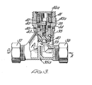
- FIG 3 is shown a valve which has been adapted to incorporate the present invention by using an adaptor bush which carries the two-part spindle of the present invention.
- valve body 35a with a flanged fluid inlet 36 and fluid outlet 37, the fluid path being indicated by the-arrows-A, B, C and D.
- the main valve aperture 39 can be closed by means of a primary valve washer 40.
- the adaptor comprises an adaptor bush 40a which carries the remaining moving parts of the valve.
- a retaining bush 41 into which may be-screwed-the valve assembly comprising an upper spindle 42, lower spindle or plunger 43 with an O ring seal or washer 44 trapped between them, and screw 45 by which adjustment of the O ring seal may be made so as to bring the upper spindle 42 and lower spindle or plunger 43 closer-together (or further apart) so as to vary the pressure on the O ring seal and thus the sealing effect of the O ring on the adaptor inner wall.
- An additional seal 46 is located between the valve body extension 38 and the adaptor bush 40a.
- the adaptor bush and all the working parts may be assembled ready to be installed into the valve body and then the adaptor bush may be threaded into the upper extension of the valve body so as to convert an existing valve body to incorporate the present invention.
- Figure 4 shows an exploded view of an alternative form of the invention in which the shape of the O ring has been varied to suit a particular design of valve.
- the upper spindle 47 has a stepped; end forming two separate steps 48 and 49.
- the sealing ring 54 is of the shape shown in Figure 4. When the parts are-assembled, as shown in Figure 5, the stem 50 enters the-recess 51 and this still leaves space for further adjustment-of the pressure on the ends of the sealing, ring 54 so that the-sealing ring 54 may be caused to bow as shown in Figure 5.
- the spindle is again in two parts an upper spindle 55 and a lower spindle 56 between which is trapped a sealing washer or O ring 57.
- the lower portion 56 carries a stem 58 which in turn supports a threaded bolt 59 which extends through an aperture 60 in the upper spindle 55.
- the adjustment is carried out by means of a nut 61 which can be turned by means of a suitable-box spanner extending through a passage 62 in the upper spindle 55.
- valves such as steam valves chemical control valves, water valves and similar valves
- O ring would be of hard rubber or of a compounded sealing material or plastic such as PTFE.
- a fluorocarbon or similar seal might be used.
- a-stop-cock which has a body 63, a threaded fluid inlet 64 and outlet 65 and a lateral extension 66 of the body 63 which receives the working parts of the valve.
- the valve has a seat 66a adapted to be closed by-means of a valve washer 67 which is supported on a jumper 68.
- the jumper 68 is of novel design- It is made of plastics metal or other suitable material and instead of being mounted--on a central spindle it is in the form of a loose snap fit or it may be swaged or folded over a flange 70 on the lower end of the valve plunger 71.
- the valve plunger 71 is integral with the lower portion 72 of the valve spindle, the upper portion 73 being of the form described with reference to Figure 4, and an O ring seal 74 being-trapped between the upper and lower portions of the valve spindle.
- the upper portion 73 of the spindle has an external thread 73a by which it can be threaded into a collar 75 in turn threaded into the upper portion 66 of the valve body.
- the assembly is completed by means of a cap 79 and final washer 78.
- the cap may be of the type shown in the previous drawings in which_case the cap has three functions. It acts as the third seal, it-protects the threads, and it can act as an on-off key for the valve.
- the external thread 80 onto which the cap is screwed may also be used to attach a fitting, as of the kind described in my UK Patent Application No. 8036761, to enable the internal working parts, and in some cases the entire valve, to be removed and replaced under pressure.
- the jumper or washer plate 68 is designed so that it has a degree of free movement, i.e. it floats thus enabling the valve washer 67 to find its own position on the seat 66a.
- The. spindle could alternatively be split into a series of separate parts or rings or plates with ring seals sandwiched between the plates so as to provide a series of seals rather than a single-seal.
- a number of rings could be used and the same principle of applying compression to the separate plates endwise could be used to vary the amount of sealing. Thus the sealing could be kept constant and uniform throughout a series of seals.
- the O ring seals of this invention prevent fluid getting to -the upper working section of the valve and thus ensure the threads in this area remain corrosion free.
- the cap can be packed with grease so that the grease enters the chamber at the top of the spindle to keep the bore of the valve and upper working parts of the valve lubricated.
- the primary valve consisting of the jumper 68 and washer 67 may take different forms.
- the jumper 68 may act-as the support for a gate valve plate or ball valve or plug valve or any similar type of fluid valve opening and dosing apparatus.
Landscapes
- Engineering & Computer Science (AREA)
- General Engineering & Computer Science (AREA)
- Mechanical Engineering (AREA)
- Details Of Valves (AREA)
- Lift Valve (AREA)
Applications Claiming Priority (8)
| Application Number | Priority Date | Filing Date | Title |
|---|---|---|---|
| GB8025859 | 1980-08-08 | ||
| GB8025859 | 1980-08-08 | ||
| GB8026474 | 1980-08-14 | ||
| GB8026474 | 1980-08-14 | ||
| GB8033948 | 1980-10-21 | ||
| GB8033948 | 1980-10-21 | ||
| GB8040529 | 1980-12-18 | ||
| GB8040529 | 1980-12-18 |
Publications (1)
| Publication Number | Publication Date |
|---|---|
| EP0046041A1 true EP0046041A1 (fr) | 1982-02-17 |
Family
ID=27449196
Family Applications (1)
| Application Number | Title | Priority Date | Filing Date |
|---|---|---|---|
| EP81303523A Withdrawn EP0046041A1 (fr) | 1980-08-08 | 1981-07-31 | Valve de contrôle pour fluide |
Country Status (1)
| Country | Link |
|---|---|
| EP (1) | EP0046041A1 (fr) |
Cited By (1)
| Publication number | Priority date | Publication date | Assignee | Title |
|---|---|---|---|---|
| CN114526356A (zh) * | 2022-03-08 | 2022-05-24 | 无锡智能自控工程股份有限公司 | 一种柱塞型分体式三通换向角阀 |
Citations (2)
| Publication number | Priority date | Publication date | Assignee | Title |
|---|---|---|---|---|
| FR1502992A (fr) * | 1965-10-28 | 1967-11-24 | Ici Ltd | Joint étanche de presse-étoupe d'un robinet |
| GB1176623A (en) * | 1967-07-11 | 1970-01-07 | Joseph Vincent Tripoli | Sealing Cartridge for Flow Control Mechanism. |
-
1981
- 1981-07-31 EP EP81303523A patent/EP0046041A1/fr not_active Withdrawn
Patent Citations (2)
| Publication number | Priority date | Publication date | Assignee | Title |
|---|---|---|---|---|
| FR1502992A (fr) * | 1965-10-28 | 1967-11-24 | Ici Ltd | Joint étanche de presse-étoupe d'un robinet |
| GB1176623A (en) * | 1967-07-11 | 1970-01-07 | Joseph Vincent Tripoli | Sealing Cartridge for Flow Control Mechanism. |
Cited By (1)
| Publication number | Priority date | Publication date | Assignee | Title |
|---|---|---|---|---|
| CN114526356A (zh) * | 2022-03-08 | 2022-05-24 | 无锡智能自控工程股份有限公司 | 一种柱塞型分体式三通换向角阀 |
Similar Documents
| Publication | Publication Date | Title |
|---|---|---|
| US3188048A (en) | Valve having radially contained packing with axially acting follower | |
| EP0246109A2 (fr) | Clapet | |
| US5799928A (en) | Ball valve with improved valve seat and bonnet assembly | |
| US2868497A (en) | High-pressure valve assembly | |
| US4231549A (en) | Valve stem and valve disc connection for a diaphragm valve | |
| US3982729A (en) | Back-up seal for diaphragm valve | |
| US3132836A (en) | Rotary plug valve having adjustable seats | |
| US5743288A (en) | Valve having provision for replacing stem packing while the valve is under pressure | |
| US4556196A (en) | Method and apparatus for sealing valve stems | |
| EP3658806B1 (fr) | Ensembles joints d'étanchéité à utiliser avec des vannes de fluide | |
| US3192948A (en) | Ball valve with sealing capsule | |
| EP0592056A2 (fr) | Soupape à boisseau sphérique | |
| EP0134866A2 (fr) | Soupape de commande | |
| US4580763A (en) | Seal-seat for use in ball valves | |
| US4630629A (en) | Valve with compressible valve stem and valve body seals | |
| US4356996A (en) | High pressure globe and check valve | |
| US5531244A (en) | Hemispherical ball valve | |
| US5407176A (en) | Back-seating of rotary valve stem | |
| US3259358A (en) | Flow control member having a radially biased seal | |
| US3217735A (en) | Valve | |
| US7971854B2 (en) | Replaceable valve shaft sealing system | |
| GB1561282A (en) | Butterfly valve thruport seal | |
| US4239185A (en) | Valve | |
| US4019536A (en) | Swing spout faucet | |
| US3893652A (en) | Means connecting gate valve and valve stem |
Legal Events
| Date | Code | Title | Description |
|---|---|---|---|
| PUAI | Public reference made under article 153(3) epc to a published international application that has entered the european phase |
Free format text: ORIGINAL CODE: 0009012 |
|
| AK | Designated contracting states |
Designated state(s): AT BE CH DE FR GB IT LU NL SE |
|
| 17P | Request for examination filed |
Effective date: 19820628 |
|
| STAA | Information on the status of an ep patent application or granted ep patent |
Free format text: STATUS: THE APPLICATION IS DEEMED TO BE WITHDRAWN |
|
| 18D | Application deemed to be withdrawn |
Effective date: 19840103 |