EP0046043A2 - Vorrichtung für den passiven Wärmetransport und integrierter Solarkollektor, in den diese Vorrichtung eingebaut ist - Google Patents
Vorrichtung für den passiven Wärmetransport und integrierter Solarkollektor, in den diese Vorrichtung eingebaut ist Download PDFInfo
- Publication number
- EP0046043A2 EP0046043A2 EP81303529A EP81303529A EP0046043A2 EP 0046043 A2 EP0046043 A2 EP 0046043A2 EP 81303529 A EP81303529 A EP 81303529A EP 81303529 A EP81303529 A EP 81303529A EP 0046043 A2 EP0046043 A2 EP 0046043A2
- Authority
- EP
- European Patent Office
- Prior art keywords
- boiler
- condenser
- liquid
- gas
- working fluid
- Prior art date
- Legal status (The legal status is an assumption and is not a legal conclusion. Google has not performed a legal analysis and makes no representation as to the accuracy of the status listed.)
- Granted
Links
Images


Classifications
-
- F—MECHANICAL ENGINEERING; LIGHTING; HEATING; WEAPONS; BLASTING
- F28—HEAT EXCHANGE IN GENERAL
- F28D—HEAT-EXCHANGE APPARATUS, NOT PROVIDED FOR IN ANOTHER SUBCLASS, IN WHICH THE HEAT-EXCHANGE MEDIA DO NOT COME INTO DIRECT CONTACT
- F28D15/00—Heat-exchange apparatus with the intermediate heat-transfer medium in closed tubes passing into or through the conduit walls ; Heat-exchange apparatus employing intermediate heat-transfer medium or bodies
- F28D15/02—Heat-exchange apparatus with the intermediate heat-transfer medium in closed tubes passing into or through the conduit walls ; Heat-exchange apparatus employing intermediate heat-transfer medium or bodies in which the medium condenses and evaporates, e.g. heat pipes
- F28D15/0266—Heat-exchange apparatus with the intermediate heat-transfer medium in closed tubes passing into or through the conduit walls ; Heat-exchange apparatus employing intermediate heat-transfer medium or bodies in which the medium condenses and evaporates, e.g. heat pipes with separate evaporating and condensing chambers connected by at least one conduit; Loop-type heat pipes; with multiple or common evaporating or condensing chambers
-
- F—MECHANICAL ENGINEERING; LIGHTING; HEATING; WEAPONS; BLASTING
- F24—HEATING; RANGES; VENTILATING
- F24S—SOLAR HEAT COLLECTORS; SOLAR HEAT SYSTEMS
- F24S90/00—Solar heat systems not otherwise provided for
- F24S90/10—Solar heat systems not otherwise provided for using thermosiphonic circulation
-
- Y—GENERAL TAGGING OF NEW TECHNOLOGICAL DEVELOPMENTS; GENERAL TAGGING OF CROSS-SECTIONAL TECHNOLOGIES SPANNING OVER SEVERAL SECTIONS OF THE IPC; TECHNICAL SUBJECTS COVERED BY FORMER USPC CROSS-REFERENCE ART COLLECTIONS [XRACs] AND DIGESTS
- Y02—TECHNOLOGIES OR APPLICATIONS FOR MITIGATION OR ADAPTATION AGAINST CLIMATE CHANGE
- Y02E—REDUCTION OF GREENHOUSE GAS [GHG] EMISSIONS, RELATED TO ENERGY GENERATION, TRANSMISSION OR DISTRIBUTION
- Y02E10/00—Energy generation through renewable energy sources
- Y02E10/40—Solar thermal energy, e.g. solar towers
Definitions
- the present invention relates to a device suitable for transporting heat in any direction and particularly downwards without the use of additional energy other than the heat energy picked up by heat source, e. g . by an integrated solar collector.
- a device for passively transporting heat from a heat source to a heat sink which device comprises a boiler for heating a working fluid, a container for condensing the vapour of the heated working fluid, means for transferring the said vapour from the boiler to the condenser, and means for transferring the working fluid from the condenser to the boiler, the said working fluid being compelled from the condenser to the boiler, when the device is in use, by the expansion of a compressible medium stored in the condenser, which medium is additionally compressed by the vapours of the working fluid when the device is in use.
- either the heat source for the boiler or the boiler itself is constituted by a solar collector.
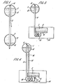
- the device of the present invention consists of two containers: an upper boiler 1, containing a suitable liquid 6, connected by a tube 2 to a lower condenser 3.
- the top end 4 of the tube 2 opens into the.upper part of the boiler 1, while the bottom end 5 of the tube opens into the lower part of the condenser 3.
- the boiler 1, which is thermally connected to a heat source as will be described later, contains a liquid 6 having a relatively low boiling point so that the upper part of the boiler will be filled, at a given temperature, with the vapour of the liquid.
- the upper part of the condenser 3 is arranged to contain an inert, immiscible, non-condensable gas 7 or a condensable gas whose liquid has a vapour pressure higher than that of the liquid 6.
- the condenser 3 is thermally connected to a heat user, (not shown for simplicity).
- the volume of the liquid 6 in the condenser increases and compresses the inert gas 7 in the upper part of the condenser.
- the compressed inert gas 7 forces the liquid 6 in the condenser, upwards through the tube 2, into the boiler, where it stays as long as the boiler is below its previous working temperature.
- the boiler is thermally connected to a solar collector as its heating source so that, during the day the liquid 6 flows downwards, as vapor, and during the night, upwards, in such a way that the system is typically discontinuous.
- the condenser 3 is provided with bellow units 8 containing a spring 9 and an amount of the same liquid more than sufficient to fill the empty space of the bellows with its vapour.
- the tension of the spring at its maximum compression, forces the liquid 6 stored in the condenser, upwards through the tube 2 and into the boiler.
- the use of a condensible gas allows a reduction of the condenser volume compared with the use of non-condensible gas.
- its liquid has, at the temperature of the condenser, at least a vapour pressure equal to the difference of the vapour pressure of the working liquid 6 at the boiler and condenser temperatures.
- the vapour when transferring the heat downwards, the vapour flows down, condenses in the lower heat exchanger and accumulates as liquid in the condenser, thus compressing the gas or the other medium contained therein.
- the volume of the condenser is made a few times (e.g. 2 to 5 times) larger than the volume of the liquid expected to be displaced, the partial pressure of the gas will increase only slightly, thus only requiring a slight increase in the boiling temperature of the liquid for same condenser temperature.
- the heat supply to the boiler ceases, the boiler cools down and the pressure existing in the condenser makes.the liquid rise back to the boiler, making the system ready for a new cycle.
- a peculiar property of the present device is that it starts to work automatically, transferring heat from top to bottom, as soon as the temperature of the boiler is afewdegrees higher than the temperature of the condenser; hence when applied to solar heat collectors, the collector itself is at the lowest possible working temperature with a beneficial effect on the heat collection efficiency of the system.
- the present device Being a system based on the transport of vapours, and having a negligible pressure drop inside the connecting tube, the present device is practically isothermal from the boiler to the first part of the condenser; any temperature differences between the boiler and the condenser being available in the condenser itself to promote heat transfer from the condenser to the heat storage medium.
- the partial pressure of the gas in the free volume of the empty condenser must be at least.equal to the hydrostatic pressure produced by the 'column of liquid in the tube connecting the boiler to the condenser.
- the system is defined once the difference between the boiler and condenser levels is fixed.
- the minimum partial pressure of the inert gas in the empty condenser is determined, and this pressure plus the vapour pressure of the working liquid at the temperature of the condenser then determines the lowest temperature at which the boiler begins to work.
- the temperature of the environment surrounding the condenser may increase slightly, and the partial pressure of the inert gas, now compressed into a smaller volume, also increases.
- the maximum temperature around the condenser and the ratio between the empty condenser volume and the volume remaining for the inert gas when all the working liquid is in the condenser, it is possible to compute the maximum temperature of the boiler towards the end of the evaporation process.
- the working liquid should have few bars vapour pressure at room temperature in order to increase by only a few degrees the boiler temperature from the beginning to the end of the evaporation process.
- Suitable fluids are: sulphur dioxide, ethylene oxide, ethylamine, pentane, acetone, methanol, ethanol, water, etc.
- An important property which the working liquid 6 should have is a high heat of evaporation, in order to avoid too large a volume for the boiler and particularly for the condenser. These volumes can be reduced if the cycles are made shorter.
- an artificial, intermittent cooling .of the collectors can be obtained by putting a body or shield in front of a row of collectors at a suitable distance therefrom. The shadow of this shield sweeping over the collectors during the day, creates as many cooling down periods as desired.
- a similar device was disclosed by O'Hanlon in the U S Patent 4089366 (1976). That device was also constituted by a boiler in the upper position, a condenser in the lower position and a tube connecting the boiler to the condenser; the working fluid was said to be sulphur dioxide.
- the recharge of the condensed liquid up to the boiler is obtained by the vapour pressure of the liquid contained in the condenser/ reservoir.
- the boiler has to cool down to a temperature much lower than the condenser, such that the difference between the vapour pressure of sulphur dioxide in the condenser and in the cool boiler is at least equal to the hydrostatic pressure created by the column of liquid sulphur dioxide between boiler and condenser.
- the presence of a pressurizing medium besides the vapour pressure of the condensed fluid, is useful for assuring the refilling of the boiler, and it would be particularly useful in summer, when the decrease of temperature at night might be insufficient to create the necessary pressure unbalance to recharge the boiler; and the increased working temperature of the boiler (due to the presence of the pressurizing medium) can be easily tolerated during the day.
- FIG 3 another embodiment of the device of the present invention is shown wherein the bottom extremity of the tube 2 is formed into a coil 13 for better condensation of the vapour before .it enters the condenser; the coil and condenser being placed within a heat storage unit 14.
- the deviceshereinbefore described are typically discontinuous, with the advantageous feature of having no mechanical moving parts.
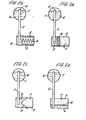
- the starting point is a device as per that already described.
- This device now contains a second tube 15, of small diameter, connecting the condenser 3, at its lowest point, to the upper part of the boiler, and having a particular one-way shut-off valve 16, preferentially located near or inside the boiler itself.
- This valve allows the flow of liquid only from the condenser 3 to the boiler 1.
- This valve requires a positive pressure difference before opening, but it is arranged to remain open until the pressure is nearly the same on both sides of the valve.. Only after this condition has been reached will it close again. Valves of this kind are already in current use.
- a further simple one-way valve 17 is placed at the end of tube 2 conveying the vapours from the boiler to the reservoir, thus allowing the flow of liquid only from the boiler to the reservoir.
- the one-way valve 17 closes, and the first part of the condenser (the enlarged portion 18 of the tube 2) behaves as a cold trap for condensing the residual vapours coming from the boiler.
- the pressure in the boiler is reduced to the vapour pressure of the liquid at the temperature of the condenser.
- the pressure difference between the condenser (still at the pressure reached during the period of normal evaporation) and the boiler, now much lower, is sufficient to open the shut-off valve 16.
- the pressure of the inert gas in the condenser then pushes the liquid back from the condenser to the boiler, and the system can continue its work of transporting another quantity of heat downwards.
- the system is able to recharge the liquid from the condenser to the boiler as soon as the pressure in the boiler decreases; be it due to a lack of liquid or to a lack of heat supply.
- the system could also be made to :operate in a pulsating mode. Depending on the temperature reached by the boiler during the final moments of its drying out, it can happen that the first drops of liquid reaching the hot boiler cause a rapid increase of pressure of the boiler, sufficient to close the shut-off valve 16 before the bulk of the liquid has reached the boiler.
- the mode of functioning of the valve 16, with a hysteresis as large as desired between opening and closing, is such that it will assure a sufficient recharging of the liquid in the boiler.
- This hysteresis which causes a higher ⁇ T between boiler and condenser, can be reduced and eventually brought to zero if a suitable device assuring a two-step charging of the liquid in the boiler is utilized at the same time.
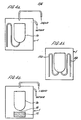
- the goal to be reached is the avoiding of an immediate contact between the recharged liquid and the hot walls of the boiler. This can be obtained, for example as shown in Figures 4a, 4b and 4c, by feeding the liquid into a small container or tray la inside the boiler having a very small heat capacity and having a bad thermal connection with the boiler walls.
- the apparatus assuring a two-step charging can also be a siphon, or simply a container with a small leak or hole lb therein and a piece of absorbing material lc under it, that will allow the liquid to reach the evaporation surface only after it is flooded.
- This latter. version is more suitable for applications when the heat supply to the boiler can be discontinuous: in fact it can happen that the cooling down of the boiler causes the recharge of the liquid from the condenser, butthat the amount of that liquid is not sufficient for triggering the discharge of the siphon.
- the device of the present invention when a bellows is used, together with the pressurizing gas there is always a sufficient amount of the working liquid, because it is an essential feature of this device that the actual working pressure is not held constant but it is the sum of the partial pressure of the gas and the vapour pressure of the working liquid at the temperature of the condenser.
- the pressure difference available for recharging the liquid into the boiler is given by the difference between the constant pressure of the gas and the vapour pressure of the working liquid at the temperature of the condenser.
- the lifting capacity is more and more reduced and can become insufficient for refilling the boiler.
- To assure this recharging the constant gas pressure must be set at a high value; obliging the boiler to be always at a high temperature with a reduced efficiency when it is coupled to a solar heat collector.
- the pressure difference available for recharging the boiler is always equal to the partial pressure of the gas, (keeping the reservoir at the same temperature as the condenser), and this will be set just to the minimum value corresponding to the hydrostatic head.
- the device is always capable of recharging the boiler, regardless of the condenser temperature, and equally importantly, the temperature of the boiler will be lower when the condenser temperature is also low.
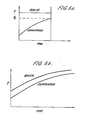
- FIGs 5a and 5b Two sketch graphs illustrating the different behaviours of the two systems when a given amount of substance is heated are shown in Figures 5a and 5b.
- the condenser and the boiler are used without a working liquid with the pressuring gas, whilst in Figure 5b they are used.with a working liquid with the pressuring gas.
- Figure 6a and 6b schematically show an example of the application of the device of the present invention to a conventional solar collector 19.
- the solar collector comprises a dark surface 20, protected by a transparent cover 21 and backed by a thermal insulation 22.
- the surface 20 contains tubes 24 through which the working fluid flows, and in this case, the fluid is the same working fluid 6 used in the devices for the downwards transport of heat.
- the liquid boils during its passage through the tubes of the solar collector, additionally enhancing its circulation, and the vapour and the liquid reach the upper part of the collector where they then enter the boiler for separation of the vapour and the liquid to occur.
- the vapour flows downwards to the condenser (not shown), and the liquid returns to the solar collector via tubes 23 in the collector for a further partial evaporation.
- the solar collector 25 itself constitutes the boiler and vapour/liquid separator.
- the collector is in the form of a flat container, horizontally disposed and having towards its centre, the tube 2 for conveying the vapours produced in the boiler/collector to the condenser.
- the boiler or the condenser or both may be arranged to have a variable volume.
Landscapes
- Engineering & Computer Science (AREA)
- General Engineering & Computer Science (AREA)
- Physics & Mathematics (AREA)
- Thermal Sciences (AREA)
- Sustainable Development (AREA)
- Mechanical Engineering (AREA)
- Life Sciences & Earth Sciences (AREA)
- Sustainable Energy (AREA)
- Chemical & Material Sciences (AREA)
- Combustion & Propulsion (AREA)
- Engine Equipment That Uses Special Cycles (AREA)
- Photovoltaic Devices (AREA)
- Thermotherapy And Cooling Therapy Devices (AREA)
Priority Applications (1)
| Application Number | Priority Date | Filing Date | Title |
|---|---|---|---|
| AT81303529T ATE8435T1 (de) | 1980-08-07 | 1981-07-31 | Vorrichtung fuer den passiven waermetransport und integrierter solarkollektor, in den diese vorrichtung eingebaut ist. |
Applications Claiming Priority (2)
| Application Number | Priority Date | Filing Date | Title |
|---|---|---|---|
| GB8025792 | 1980-08-07 | ||
| GB8025792A GB2081435A (en) | 1980-08-07 | 1980-08-07 | Device for passive downwards heat transport and integrated solar collectur incorporating same |
Publications (3)
| Publication Number | Publication Date |
|---|---|
| EP0046043A2 true EP0046043A2 (de) | 1982-02-17 |
| EP0046043A3 EP0046043A3 (en) | 1982-04-14 |
| EP0046043B1 EP0046043B1 (de) | 1984-07-11 |
Family
ID=10515300
Family Applications (1)
| Application Number | Title | Priority Date | Filing Date |
|---|---|---|---|
| EP81303529A Expired EP0046043B1 (de) | 1980-08-07 | 1981-07-31 | Vorrichtung für den passiven Wärmetransport und integrierter Solarkollektor, in den diese Vorrichtung eingebaut ist |
Country Status (8)
| Country | Link |
|---|---|
| US (1) | US4467862A (de) |
| EP (1) | EP0046043B1 (de) |
| JP (1) | JPS57112658A (de) |
| AT (1) | ATE8435T1 (de) |
| CA (1) | CA1185495A (de) |
| DE (1) | DE3164717D1 (de) |
| ES (1) | ES8206006A1 (de) |
| GB (1) | GB2081435A (de) |
Cited By (1)
| Publication number | Priority date | Publication date | Assignee | Title |
|---|---|---|---|---|
| AU595605B2 (en) * | 1986-05-22 | 1990-04-05 | European Atomic Energy Community (Euratom) | A passive heat transfer device |
Families Citing this family (13)
| Publication number | Priority date | Publication date | Assignee | Title |
|---|---|---|---|---|
| US4603685A (en) * | 1983-06-21 | 1986-08-05 | Institut National De La Recherche Scientifique | Solar heating system |
| JPS6131884A (ja) * | 1984-07-24 | 1986-02-14 | Kenji Okayasu | 熱伝達装置 |
| US4611654A (en) * | 1985-01-23 | 1986-09-16 | Buchsel Christian K E | Passive system for heat transfer |
| WO1989009370A1 (en) * | 1988-03-24 | 1989-10-05 | The University Of Sydney | Solar heating system |
| US5178209A (en) * | 1988-07-12 | 1993-01-12 | Sanden Corporation | Condenser for automotive air conditioning systems |
| US5172758A (en) * | 1989-02-01 | 1992-12-22 | Sanden Corporation | Condenser with a built-in receiver |
| US5083605A (en) * | 1990-08-17 | 1992-01-28 | Sundstrand Corporaiton | Self-pumping phase change thermal energy device |
| GB2280744A (en) * | 1993-08-03 | 1995-02-08 | Isoterix Ltd | Inverted heatpipes |
| US6042342A (en) * | 1996-10-02 | 2000-03-28 | T.D.I. --Thermo Dynamics Israel Ltd. | Fluid displacement system |
| GB2489401B (en) * | 2011-03-21 | 2014-04-23 | Naked Energy Ltd | Solar energy converter |
| FR2985808B1 (fr) * | 2012-01-13 | 2018-06-15 | Airbus Defence And Space | Dispositif de refroidissement adapte a la regulation thermique d'une source de chaleur d'un satellite, procede de realisation du dispositif de refroidissement et satellite associes |
| GB2502629B (en) * | 2012-06-01 | 2015-03-11 | Siemens Plc | A closed cryogen cooling system and method for cooling a superconducting magnet |
| RU2553827C1 (ru) * | 2014-02-25 | 2015-06-20 | Александр Михайлович Деревягин | Способ и устройство для теплопередачи |
Family Cites Families (12)
| Publication number | Priority date | Publication date | Assignee | Title |
|---|---|---|---|---|
| US3929305A (en) * | 1972-10-27 | 1975-12-30 | Nasa | Heat exchanger system and method |
| US3951204A (en) * | 1974-07-22 | 1976-04-20 | Movick Nyle O | Method and apparatus for thermally circulating a liquid |
| GB1541221A (en) * | 1976-04-13 | 1979-02-28 | British Petroleum Co | Solar energy collector |
| US4050509A (en) * | 1976-10-28 | 1977-09-27 | Dynatherm Corporation | Down-pumping heat pipes |
| US4089366A (en) * | 1976-11-22 | 1978-05-16 | Hanlon Edward J O | Means and methods for sending heat downwardly |
| GB1558551A (en) * | 1977-02-23 | 1980-01-03 | Org Europeene De Rech | Pressure pump heat transfer system |
| US4120172A (en) * | 1977-05-05 | 1978-10-17 | The United States Of America As Represented By The United States Department Of Energy | Heat transport system |
| DE2727176A1 (de) * | 1977-06-16 | 1978-12-21 | Messerschmitt Boelkow Blohm | Solare heizungs/kraftwerksanlage |
| JPS5430552A (en) * | 1977-08-12 | 1979-03-07 | Hitachi Ltd | Boiling cooling apparatus |
| DE2739199B2 (de) * | 1977-08-31 | 1979-08-23 | Dornier System Gmbh, 7990 Friedrichshafen | Schalt- und regelbares Wärmerohr |
| DD140909A1 (de) * | 1978-12-20 | 1980-04-02 | Bernd Guetzold | Heizanlage zur uebertragung der energie aus sonnenkollektoren |
| US4357932A (en) * | 1980-05-29 | 1982-11-09 | Creare Incorporated | Self pumped solar energy collection system |
-
1980
- 1980-08-07 GB GB8025792A patent/GB2081435A/en not_active Withdrawn
-
1981
- 1981-07-31 DE DE8181303529T patent/DE3164717D1/de not_active Expired
- 1981-07-31 AT AT81303529T patent/ATE8435T1/de not_active IP Right Cessation
- 1981-07-31 ES ES504464A patent/ES8206006A1/es not_active Expired
- 1981-07-31 EP EP81303529A patent/EP0046043B1/de not_active Expired
- 1981-08-06 CA CA000383358A patent/CA1185495A/en not_active Expired
- 1981-08-06 JP JP56123565A patent/JPS57112658A/ja active Pending
-
1982
- 1982-11-12 US US06/441,113 patent/US4467862A/en not_active Expired - Lifetime
Cited By (1)
| Publication number | Priority date | Publication date | Assignee | Title |
|---|---|---|---|---|
| AU595605B2 (en) * | 1986-05-22 | 1990-04-05 | European Atomic Energy Community (Euratom) | A passive heat transfer device |
Also Published As
| Publication number | Publication date |
|---|---|
| CA1185495A (en) | 1985-04-16 |
| ES504464A0 (es) | 1982-06-16 |
| DE3164717D1 (en) | 1984-08-16 |
| JPS57112658A (en) | 1982-07-13 |
| ATE8435T1 (de) | 1984-07-15 |
| US4467862A (en) | 1984-08-28 |
| GB2081435A (en) | 1982-02-17 |
| EP0046043A3 (en) | 1982-04-14 |
| ES8206006A1 (es) | 1982-06-16 |
| EP0046043B1 (de) | 1984-07-11 |
Similar Documents
| Publication | Publication Date | Title |
|---|---|---|
| EP0046043B1 (de) | Vorrichtung für den passiven Wärmetransport und integrierter Solarkollektor, in den diese Vorrichtung eingebaut ist | |
| US4254820A (en) | Heat transport device | |
| US4119143A (en) | Heat transfer system | |
| US6042342A (en) | Fluid displacement system | |
| US4217765A (en) | Heat exchanger-accumulator | |
| US4382466A (en) | Thermosiphon | |
| CN105674780B (zh) | 一种反重力热管 | |
| US4576009A (en) | Heat transmission device | |
| US4357932A (en) | Self pumped solar energy collection system | |
| CN104803011B (zh) | 月球车温控系统 | |
| US4603685A (en) | Solar heating system | |
| US2212281A (en) | Refrigeration | |
| US4382437A (en) | Self-contained passive solar heating system | |
| US4224925A (en) | Heating system | |
| US4299275A (en) | Heat transfer system | |
| US4407129A (en) | Closed loop solar collecting system operating a thermoelectric generator system | |
| US4203422A (en) | Solar heating system and component | |
| EP0588802B1 (de) | Wärmerohrvorrichtung | |
| US4241784A (en) | Arrangements for the transfer of heat from an upper level to a lower level | |
| US20030121515A1 (en) | Counter - thermosyphon loop heat pipe solar collector | |
| US4354483A (en) | Closed loop solar collector system with dual reservoirs and fluid bypass | |
| US4397300A (en) | Closed loop solar collector system with dual chamber fluid supply arrangement | |
| US4412529A (en) | Closed loop solar collector system with dual reservoirs and fluid bypass | |
| US4537036A (en) | Thermally powered heating system | |
| AU770892B2 (en) | Water heater with vapour phase downward heat transfer |
Legal Events
| Date | Code | Title | Description |
|---|---|---|---|
| PUAI | Public reference made under article 153(3) epc to a published international application that has entered the european phase |
Free format text: ORIGINAL CODE: 0009012 |
|
| PUAL | Search report despatched |
Free format text: ORIGINAL CODE: 0009013 |
|
| AK | Designated contracting states |
Designated state(s): AT BE CH DE FR GB IT LU NL SE |
|
| AK | Designated contracting states |
Designated state(s): AT BE CH DE FR GB IT LU NL SE |
|
| 17P | Request for examination filed |
Effective date: 19820805 |
|
| ITF | It: translation for a ep patent filed | ||
| GRAA | (expected) grant |
Free format text: ORIGINAL CODE: 0009210 |
|
| AK | Designated contracting states |
Designated state(s): AT BE CH DE FR GB IT LI LU NL SE |
|
| REF | Corresponds to: |
Ref document number: 8435 Country of ref document: AT Date of ref document: 19840715 Kind code of ref document: T |
|
| REF | Corresponds to: |
Ref document number: 3164717 Country of ref document: DE Date of ref document: 19840816 |
|
| ET | Fr: translation filed | ||
| PLBE | No opposition filed within time limit |
Free format text: ORIGINAL CODE: 0009261 |
|
| STAA | Information on the status of an ep patent application or granted ep patent |
Free format text: STATUS: NO OPPOSITION FILED WITHIN TIME LIMIT |
|
| 26N | No opposition filed | ||
| ITTA | It: last paid annual fee | ||
| EPTA | Lu: last paid annual fee | ||
| EAL | Se: european patent in force in sweden |
Ref document number: 81303529.2 |
|
| PGFP | Annual fee paid to national office [announced via postgrant information from national office to epo] |
Ref country code: BE Payment date: 19980428 Year of fee payment: 18 |
|
| PGFP | Annual fee paid to national office [announced via postgrant information from national office to epo] |
Ref country code: LU Payment date: 19980504 Year of fee payment: 18 |
|
| PGFP | Annual fee paid to national office [announced via postgrant information from national office to epo] |
Ref country code: GB Payment date: 19980522 Year of fee payment: 18 |
|
| PGFP | Annual fee paid to national office [announced via postgrant information from national office to epo] |
Ref country code: AT Payment date: 19980612 Year of fee payment: 18 |
|
| PGFP | Annual fee paid to national office [announced via postgrant information from national office to epo] |
Ref country code: SE Payment date: 19980615 Year of fee payment: 18 |
|
| PGFP | Annual fee paid to national office [announced via postgrant information from national office to epo] |
Ref country code: CH Payment date: 19980619 Year of fee payment: 18 |
|
| PGFP | Annual fee paid to national office [announced via postgrant information from national office to epo] |
Ref country code: DE Payment date: 19980729 Year of fee payment: 18 |
|
| PGFP | Annual fee paid to national office [announced via postgrant information from national office to epo] |
Ref country code: NL Payment date: 19980731 Year of fee payment: 18 Ref country code: FR Payment date: 19980731 Year of fee payment: 18 |
|
| PG25 | Lapsed in a contracting state [announced via postgrant information from national office to epo] |
Ref country code: SE Free format text: THE PATENT HAS BEEN ANNULLED BY A DECISION OF A NATIONAL AUTHORITY Effective date: 19990730 |
|
| PG25 | Lapsed in a contracting state [announced via postgrant information from national office to epo] |
Ref country code: LU Free format text: LAPSE BECAUSE OF NON-PAYMENT OF DUE FEES Effective date: 19990731 Ref country code: LI Free format text: LAPSE BECAUSE OF NON-PAYMENT OF DUE FEES Effective date: 19990731 Ref country code: GB Free format text: LAPSE BECAUSE OF NON-PAYMENT OF DUE FEES Effective date: 19990731 Ref country code: FR Free format text: THE PATENT HAS BEEN ANNULLED BY A DECISION OF A NATIONAL AUTHORITY Effective date: 19990731 Ref country code: CH Free format text: LAPSE BECAUSE OF NON-PAYMENT OF DUE FEES Effective date: 19990731 Ref country code: BE Free format text: LAPSE BECAUSE OF NON-PAYMENT OF DUE FEES Effective date: 19990731 Ref country code: AT Free format text: LAPSE BECAUSE OF NON-PAYMENT OF DUE FEES Effective date: 19990731 |
|
| BERE | Be: lapsed |
Owner name: EUROPEAN ATOMIC ENERGY COMMUNITY ( EURATOM) Effective date: 19990731 |
|
| PG25 | Lapsed in a contracting state [announced via postgrant information from national office to epo] |
Ref country code: NL Free format text: LAPSE BECAUSE OF NON-PAYMENT OF DUE FEES Effective date: 20000201 |
|
| REG | Reference to a national code |
Ref country code: CH Ref legal event code: PL |
|
| GBPC | Gb: european patent ceased through non-payment of renewal fee |
Effective date: 19990731 |
|
| NLV4 | Nl: lapsed or anulled due to non-payment of the annual fee |
Effective date: 20000201 |
|
| EUG | Se: european patent has lapsed |
Ref document number: 81303529.2 |
|
| PG25 | Lapsed in a contracting state [announced via postgrant information from national office to epo] |
Ref country code: DE Free format text: LAPSE BECAUSE OF NON-PAYMENT OF DUE FEES Effective date: 20000503 |
|
| REG | Reference to a national code |
Ref country code: FR Ref legal event code: ST |