EP0046246A2 - Dispositif d'élimination d'hydrogène de l'enceinte de sécurité d'un réacteur nucléaire - Google Patents
Dispositif d'élimination d'hydrogène de l'enceinte de sécurité d'un réacteur nucléaire Download PDFInfo
- Publication number
- EP0046246A2 EP0046246A2 EP81106179A EP81106179A EP0046246A2 EP 0046246 A2 EP0046246 A2 EP 0046246A2 EP 81106179 A EP81106179 A EP 81106179A EP 81106179 A EP81106179 A EP 81106179A EP 0046246 A2 EP0046246 A2 EP 0046246A2
- Authority
- EP
- European Patent Office
- Prior art keywords
- gas mixture
- hydrogen
- safety container
- housing
- recombiner
- Prior art date
- Legal status (The legal status is an assumption and is not a legal conclusion. Google has not performed a legal analysis and makes no representation as to the accuracy of the status listed.)
- Granted
Links
Images
Classifications
-
- G—PHYSICS
- G21—NUCLEAR PHYSICS; NUCLEAR ENGINEERING
- G21C—NUCLEAR REACTORS
- G21C19/00—Arrangements for treating, for handling, or for facilitating the handling of, fuel or other materials which are used within the reactor, e.g. within its pressure vessel
- G21C19/28—Arrangements for introducing fluent material into the reactor core; Arrangements for removing fluent material from the reactor core
- G21C19/30—Arrangements for introducing fluent material into the reactor core; Arrangements for removing fluent material from the reactor core with continuous purification of circulating fluent material, e.g. by extraction of fission products deterioration or corrosion products, impurities, e.g. by cold traps
-
- G—PHYSICS
- G21—NUCLEAR PHYSICS; NUCLEAR ENGINEERING
- G21D—NUCLEAR POWER PLANT
- G21D1/00—Details of nuclear power plant
- G21D1/02—Arrangements of auxiliary equipment
-
- Y—GENERAL TAGGING OF NEW TECHNOLOGICAL DEVELOPMENTS; GENERAL TAGGING OF CROSS-SECTIONAL TECHNOLOGIES SPANNING OVER SEVERAL SECTIONS OF THE IPC; TECHNICAL SUBJECTS COVERED BY FORMER USPC CROSS-REFERENCE ART COLLECTIONS [XRACs] AND DIGESTS
- Y02—TECHNOLOGIES OR APPLICATIONS FOR MITIGATION OR ADAPTATION AGAINST CLIMATE CHANGE
- Y02E—REDUCTION OF GREENHOUSE GAS [GHG] EMISSIONS, RELATED TO ENERGY GENERATION, TRANSMISSION OR DISTRIBUTION
- Y02E30/00—Energy generation of nuclear origin
- Y02E30/30—Nuclear fission reactors
Definitions
- the invention relates to a device for removing hydrogen gas from the safety container of a nuclear reactor system using a thermal recombiner, which consists of a metallic housing and baffles for the gas flow arranged therein, and has a supply line for the hydrogen-enriched gas mixture and a discharge line for the hydrogen-poor gas mixture. ,
- the gas mixture is heated and reached via the hot room air then in the reaction chamber, which is also located in this room.
- the now low-hydrogen gas mixture leaves the insulated room via a pipe and, after it has released its residual heat to a heat exchanger, returns to the safety container.
- This type of heating requires a large amount of space.
- the device can only be operated if the hydrogen content of the gas mixture introduced is below the lower explosion limit of 4% by volume.
- the object of the invention is therefore to provide a device of the type mentioned at the outset, which has a compact heating device and allows the safe processing of all gas mixture concentrations.
- the object is achieved in that the wall of the housing and the baffle plates are inductively heated and that the supply line for the hydrogen-enriched gas mixture is connected to the discharge line for the hydrogen-poor gas mixture via a three-way valve, the third outlet of which leads part of the low-hydrogen gas mixture to the safety container .
- the housing of the recombiner is preferably an elongated tubular body the at least partially by one is surrounded.
- the area of the housing wall surrounded by the induction winding is reinforced and the deflection plates contact the inside of the wall in a kind of frictional connection.
- a similar effect is achieved in that the baffle plates are welded to a thick-walled pipe section and the pipe section forms the frictional connection on the circumferential side with the inside of the housing wall.
- the gas flowing in the connecting line between the three-way valve and the safety container and in the supply line in the area between the safety container and a recuperative heat exchanger is preferably kept at a temperature which is higher than the temperature prevailing in the safety container by means of a trace heating.
- a trace heating This measure has the advantage that there is no formation of condensate in the line system and therefore no highly radioactive condensate is produced outside the containment.
- the trace heating also absorbs the water produced during the combustion of the hydrogen by the low-hydrogen gas mixture.
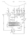
- the device is described using an exemplary embodiment and a schematic drawing.
- Hydrogen-enriched gas mixture which has formed there in an impermissible enrichment, is removed from the safety container 1 of a nuclear reactor system (not shown further) with the aid of the blower 2 and the feed line 3 and fed into the recombiner 4.
- the housing 5 of the recombiner is a cylindrical, elongated tubular body which is hemispherically closed at both ends.
- Deflection plates 6 made of stainless steel are arranged in the cylindrical part of the housing and serve as static mixing elements.
- the upper half of the housing is covered by a water-cooled winding 7 heated inductively. The eddy currents are induced not only in the housing wall 8 but also in the deflection plates 6, so that a homogeneous temperature distribution is ensured.
- Insulation 13 attached to the cylindrical part of the housing 5 simultaneously protects the induction winding from excessive heat load.
- the self-heating of the induction winding is released via a cooling circuit 14.
- the cooling circuit is equipped with measuring points 15, 16, a recuperative heat exchanger 17, a shut-off valve 18 and a control valve 19. It is connected to a line system, not shown, via quick-action couplings 20.
- the deflection plates 6 are welded to a thick-walled tube piece 9, which enters into a kind of frictional connection on the circumference and contacts the inside of the housing wall 8. Durr: h this intimate connection, an effective heat input is achieved.
- the upper half of the recombiner is used to heat up to the operating temperature of 700-750 ° C.
- the residence time of the hot gas mixture for the complete reaction is approx. 0.5 seconds.
- a homogeneous temperature distribution is achieved by appropriate design of the baffle plates. With a throughput of 180 m 3 / h (iN) for a total residence time of 1 sec. a total of approx. 50 liters total volume of the recombiner is required. This volume is achieved, for example, by a housing 5 which consists of a 1500 mm long pipe with a nominal diameter of 250 mm. Following the combustion of the now low-hydrogen gas mixture to R ekombinator leaves via the discharge line 10. With the aid of the temperature measuring point 11, the necessary heating capacity of the induction coil 7 is controlled. The gas mixture releases part of its heat when flowing through a recuperative heat exchanger 12.
- the gas mixture flowing in the feed line 3 is preheated.
- the gas mixture located in the discharge line 3 is cooled to 60 to 65 ° C. in the recuperative heat exchanger 17.
- the gas mixture cooled to this point now arrives at a remotely controllable three-way valve 21. From here, the major part of the low-hydrogen gas mixture flows via the outlet 22 of the three-way valve and the line 23 through a flame arrester 34 back to the safety container 1.
- the remaining rest of the gas mixture reaches the connecting line 3a to the feed line 3 and serves to dilute the hydrogen-enriched gas mixture brought in by the containment.
- the amount of the gas mixture brought in by the connecting line 3a depends on the hydrogen content of the gas mixture brought in from the containment. It is controlled via the three-way valve so that the gas mixture leading to the recombiner is always below 4% by volume of hydrogen. A dangerous deflagration is thus prevented with certainty.
- Flow measuring devices 27, 28, pressure measuring devices 29, 30, 31, temperature sensors 32, 33 and a flame arrester 34 are installed in the supply line 3 and the connecting line 3a.
- the line 23 is heated via a trace heater (not shown) in order to keep the gas mixture at a temperature of 60-65 ° C.
- the area of the supply line 3 between the safety container 1 and the recuperative heat exchanger 12 is also provided with a trace heating, not shown.
- the temperature of the gas mixture flowing therein is thereby kept at a higher value than the temperature measured inside the containment.
- this measure is intended to avoid any highly radioactive condensate accumulation outside the containment.
Landscapes
- Physics & Mathematics (AREA)
- Engineering & Computer Science (AREA)
- Plasma & Fusion (AREA)
- General Engineering & Computer Science (AREA)
- High Energy & Nuclear Physics (AREA)
- Structure Of Emergency Protection For Nuclear Reactors (AREA)
Priority Applications (1)
| Application Number | Priority Date | Filing Date | Title |
|---|---|---|---|
| AT81106179T ATE12850T1 (de) | 1980-08-20 | 1981-08-07 | Einrichtung zur entfernung von wasserstoffgas aus dem sicherheitsbehaelter einer kernreaktoranlage. |
Applications Claiming Priority (2)
| Application Number | Priority Date | Filing Date | Title |
|---|---|---|---|
| DE3031378A DE3031378C2 (de) | 1980-08-20 | 1980-08-20 | Einrichtung zur Entfernung von Wasserstoffgas aus dem Sicherheitsbehälter einer Kernreaktoranlage |
| DE3031378 | 1980-08-20 |
Publications (3)
| Publication Number | Publication Date |
|---|---|
| EP0046246A2 true EP0046246A2 (fr) | 1982-02-24 |
| EP0046246A3 EP0046246A3 (en) | 1982-05-05 |
| EP0046246B1 EP0046246B1 (fr) | 1985-04-17 |
Family
ID=6110003
Family Applications (1)
| Application Number | Title | Priority Date | Filing Date |
|---|---|---|---|
| EP81106179A Expired EP0046246B1 (fr) | 1980-08-20 | 1981-08-07 | Dispositif d'élimination d'hydrogène de l'enceinte de sécurité d'un réacteur nucléaire |
Country Status (6)
| Country | Link |
|---|---|
| EP (1) | EP0046246B1 (fr) |
| JP (1) | JPS5772098A (fr) |
| AT (1) | ATE12850T1 (fr) |
| CA (1) | CA1160367A (fr) |
| DE (1) | DE3031378C2 (fr) |
| ES (1) | ES505355A0 (fr) |
Cited By (2)
| Publication number | Priority date | Publication date | Assignee | Title |
|---|---|---|---|---|
| EP0217377A3 (fr) * | 1985-10-02 | 1987-06-10 | Westinghouse Electric Corporation | Appareil pour brûler des gaz contenant de l'hydrogène et pour refroidir les gaz de combustion produits |
| EP0338678A1 (fr) * | 1988-04-22 | 1989-10-25 | Ngk Insulators, Ltd. | Dispositif de recombinaison pour gaz perdu radioactif |
Families Citing this family (5)
| Publication number | Priority date | Publication date | Assignee | Title |
|---|---|---|---|---|
| DE3614267A1 (de) * | 1986-04-26 | 1987-10-29 | Siemens Ag | Kernkraftwerk mit einem wassergekuehlten reaktordruckbehaelter |
| DE19503541A1 (de) * | 1995-02-03 | 1996-08-08 | Abb Management Ag | Verfahren und Vorrichtung zum Absaugen der Kondensatorabgase eines Siedewasserreaktors |
| DE19751171C1 (de) * | 1997-11-19 | 1999-07-15 | Forschungszentrum Juelich Gmbh | Vorrichtung zur Kühlung inertisierter Störfallatmosphären und zur Abtrennung und Beseitigung von Wasserstoff |
| DE102005040158B3 (de) | 2005-08-25 | 2007-02-22 | Hansa Metallwerke Ag | Sanitäre Auslaufarmatur, insbesondere Einhebelmischer |
| JP6034165B2 (ja) * | 2012-12-03 | 2016-11-30 | 株式会社東芝 | 水素除去装置 |
Family Cites Families (6)
| Publication number | Priority date | Publication date | Assignee | Title |
|---|---|---|---|---|
| DE1498588A1 (de) * | 1963-10-12 | 1969-05-22 | Brown Boveri Krupp Reaktor | Verfahren und Vorrichtung zum Nachweis und zur Bestimmung von gas- oder dampffoermigen Beimischungen in gas- oder dampffoermigen Medien |
| US3658996A (en) * | 1969-02-03 | 1972-04-25 | Westinghouse Electric Corp | System for the removal of hydrogen from nuclear containment structures |
| BE788538A (fr) * | 1971-09-09 | 1973-03-08 | Westinghouse Electric Corp | Appareil de recombinaison de l'hydrogene et de l'oxygene |
| US3791923A (en) * | 1972-01-10 | 1974-02-12 | Universal Oil Prod Co | Recuperative thermal recombining system for handling loss of reactor coolant |
| US3853482A (en) * | 1972-01-10 | 1974-12-10 | Universal Oil Prod Co | Recuperative thermal recombining system for handling loss of coolant |
| US4019871A (en) * | 1974-09-30 | 1977-04-26 | General Electric Company | Recombiner apparatus |
-
1980
- 1980-08-20 DE DE3031378A patent/DE3031378C2/de not_active Expired
-
1981
- 1981-08-07 EP EP81106179A patent/EP0046246B1/fr not_active Expired
- 1981-08-07 AT AT81106179T patent/ATE12850T1/de not_active IP Right Cessation
- 1981-08-19 CA CA000384222A patent/CA1160367A/fr not_active Expired
- 1981-08-20 ES ES505355A patent/ES505355A0/es active Granted
- 1981-08-20 JP JP56129469A patent/JPS5772098A/ja active Pending
Cited By (2)
| Publication number | Priority date | Publication date | Assignee | Title |
|---|---|---|---|---|
| EP0217377A3 (fr) * | 1985-10-02 | 1987-06-10 | Westinghouse Electric Corporation | Appareil pour brûler des gaz contenant de l'hydrogène et pour refroidir les gaz de combustion produits |
| EP0338678A1 (fr) * | 1988-04-22 | 1989-10-25 | Ngk Insulators, Ltd. | Dispositif de recombinaison pour gaz perdu radioactif |
Also Published As
| Publication number | Publication date |
|---|---|
| CA1160367A (fr) | 1984-01-10 |
| ES8306283A1 (es) | 1983-05-01 |
| JPS5772098A (en) | 1982-05-06 |
| EP0046246B1 (fr) | 1985-04-17 |
| DE3031378A1 (de) | 1982-05-13 |
| ATE12850T1 (de) | 1985-05-15 |
| DE3031378C2 (de) | 1983-04-07 |
| EP0046246A3 (en) | 1982-05-05 |
| ES505355A0 (es) | 1983-05-01 |
Similar Documents
| Publication | Publication Date | Title |
|---|---|---|
| DE3046933C2 (de) | Wasserstandsmeßvorrichtung für einen Kernreaktor | |
| DD256372A5 (de) | Entnahmesonde für heiße Gasproben | |
| DE2730124A1 (de) | Schnellneutronen-kernreaktor | |
| EP0160225B1 (fr) | Procédé pour dissiper ou fournir de la chaleur dans un tube vertical | |
| DE1097048B (de) | Kernreaktoranlage mit Druckbehaelter | |
| DE3031378C2 (de) | Einrichtung zur Entfernung von Wasserstoffgas aus dem Sicherheitsbehälter einer Kernreaktoranlage | |
| DE2220486C3 (de) | Druckwasserreaktor | |
| DE2411006C2 (de) | Vorrichtung zur Gasphasenumsetzung von Wasserstoff und Sauerstoff | |
| DE2746457A1 (de) | Rohrplatte, die zwei mit zwischenraum aufgestellte plattenfoermige teile umfasst - waermetaucher, der wenigstens eine solche rohrplatte umfasst | |
| DE2851206B2 (de) | Heizungsanlage mit einem Heizkessel und einem rauchgasbeheizten Wassererhitzer zur Aufheizung einer Teilstrommenge des Heizwasser-Rücklaufes | |
| DE2937021C2 (de) | Meßgerät und Meßanordnung zur Feststellung von Undichtigkeiten im Kühlflüssigkeitskreislauf von Hochofendüsen | |
| DE2807974C2 (de) | Einrichtung zur Borierung von Primärkühlmittel in einer wassergekühlten Kernreaktoranlage | |
| DE1564054C3 (de) | Kernreaktor | |
| EP0149771B1 (fr) | Système inductif pour mesurer l'écoulement à l'aide de sondes | |
| DE3930579C2 (fr) | ||
| DE1464795A1 (de) | Kernreaktor mit Reaktivitaetssteuerung | |
| EP0725406B1 (fr) | Procédé et appareil pour recombiner l'hydrogène et l'oxygène du condenseur principal d'un réacteur nucléaire à eau bouillante | |
| DE1221372B (de) | Atomkernreaktoranlage | |
| DE1489950B1 (de) | Notkondensationsanlage fuer dampfgekuehlte Kernreaktoren | |
| DE2216714C2 (de) | Anschlußelement für einen Wärmetauscher in Tauchrohrbauweise | |
| DE2113416C2 (de) | Überhitzungs-Schutzvorrichtung für die Flüssigkeitsrohre eines Durchlauferhitzers | |
| DE1573539C (de) | Anordnung zur Versorgung von Versuchs schleifen zur Matenaluntersuchung in einem Stromungskreislauf | |
| DE3205297C2 (de) | Vorrichtung zum Vermischen zweier Fluide stark unterschiedlicher Temperaturen | |
| DE2824667C2 (de) | Dampfbeheizter Wärmeübertrager, insbesondere für kondensatseitige Regelung der Wärmeübertragung | |
| DE2702003C2 (de) | Vorrichtung zur Überprüfung eines Brennelementes eines flüssigmetallgekühlten Reaktors |
Legal Events
| Date | Code | Title | Description |
|---|---|---|---|
| PUAI | Public reference made under article 153(3) epc to a published international application that has entered the european phase |
Free format text: ORIGINAL CODE: 0009012 |
|
| AK | Designated contracting states |
Designated state(s): AT CH FR GB IT LI |
|
| PUAL | Search report despatched |
Free format text: ORIGINAL CODE: 0009013 |
|
| RAP1 | Party data changed (applicant data changed or rights of an application transferred) |
Owner name: BROWN BOVERI REAKTOR GMBH |
|
| RAP1 | Party data changed (applicant data changed or rights of an application transferred) |
Owner name: BROWN BOVERI REAKTOR GMBH |
|
| AK | Designated contracting states |
Designated state(s): AT CH FR GB IT LI |
|
| 17P | Request for examination filed |
Effective date: 19821028 |
|
| ITF | It: translation for a ep patent filed | ||
| GRAA | (expected) grant |
Free format text: ORIGINAL CODE: 0009210 |
|
| AK | Designated contracting states |
Designated state(s): AT CH FR GB IT LI |
|
| REF | Corresponds to: |
Ref document number: 12850 Country of ref document: AT Date of ref document: 19850515 Kind code of ref document: T |
|
| ET | Fr: translation filed | ||
| PLBE | No opposition filed within time limit |
Free format text: ORIGINAL CODE: 0009261 |
|
| STAA | Information on the status of an ep patent application or granted ep patent |
Free format text: STATUS: NO OPPOSITION FILED WITHIN TIME LIMIT |
|
| 26N | No opposition filed | ||
| PGFP | Annual fee paid to national office [announced via postgrant information from national office to epo] |
Ref country code: AT Payment date: 19860704 Year of fee payment: 6 |
|
| PG25 | Lapsed in a contracting state [announced via postgrant information from national office to epo] |
Ref country code: GB Free format text: LAPSE BECAUSE OF NON-PAYMENT OF DUE FEES Effective date: 19880807 Ref country code: AT Effective date: 19880807 |
|
| PG25 | Lapsed in a contracting state [announced via postgrant information from national office to epo] |
Ref country code: FR Free format text: LAPSE BECAUSE OF NON-PAYMENT OF DUE FEES Effective date: 19890428 |
|
| GBPC | Gb: european patent ceased through non-payment of renewal fee | ||
| REG | Reference to a national code |
Ref country code: FR Ref legal event code: ST |
|
| PGFP | Annual fee paid to national office [announced via postgrant information from national office to epo] |
Ref country code: CH Payment date: 19890728 Year of fee payment: 9 |
|
| PG25 | Lapsed in a contracting state [announced via postgrant information from national office to epo] |
Ref country code: LI Effective date: 19900831 Ref country code: CH Effective date: 19900831 |
|
| REG | Reference to a national code |
Ref country code: CH Ref legal event code: PL |