EP0046303A2 - Assemblage de contact pour un sectionneur - Google Patents
Assemblage de contact pour un sectionneur Download PDFInfo
- Publication number
- EP0046303A2 EP0046303A2 EP81106410A EP81106410A EP0046303A2 EP 0046303 A2 EP0046303 A2 EP 0046303A2 EP 81106410 A EP81106410 A EP 81106410A EP 81106410 A EP81106410 A EP 81106410A EP 0046303 A2 EP0046303 A2 EP 0046303A2
- Authority
- EP
- European Patent Office
- Prior art keywords
- stationary arm
- ring
- arm
- electric field
- contact assembly
- Prior art date
- Legal status (The legal status is an assumption and is not a legal conclusion. Google has not performed a legal analysis and makes no representation as to the accuracy of the status listed.)
- Granted
Links
- 239000002184 metal Substances 0.000 claims abstract description 20
- 239000012212 insulator Substances 0.000 claims abstract description 18
- 239000011248 coating agent Substances 0.000 claims abstract description 10
- 238000000576 coating method Methods 0.000 claims abstract description 10
- 230000005684 electric field Effects 0.000 claims description 23
- 239000000463 material Substances 0.000 claims description 6
- 238000009413 insulation Methods 0.000 description 15
- 239000004020 conductor Substances 0.000 description 5
- 239000003973 paint Substances 0.000 description 4
- 238000010276 construction Methods 0.000 description 2
- 239000011810 insulating material Substances 0.000 description 2
- 238000005192 partition Methods 0.000 description 2
- 229920005989 resin Polymers 0.000 description 2
- 239000011347 resin Substances 0.000 description 2
- OKTJSMMVPCPJKN-UHFFFAOYSA-N Carbon Chemical compound [C] OKTJSMMVPCPJKN-UHFFFAOYSA-N 0.000 description 1
- 230000002238 attenuated effect Effects 0.000 description 1
- 229910052799 carbon Inorganic materials 0.000 description 1
- 239000002131 composite material Substances 0.000 description 1
- 230000003247 decreasing effect Effects 0.000 description 1
- 239000003822 epoxy resin Substances 0.000 description 1
- 238000002474 experimental method Methods 0.000 description 1
- 238000003780 insertion Methods 0.000 description 1
- 230000037431 insertion Effects 0.000 description 1
- 229920000647 polyepoxide Polymers 0.000 description 1
- 229920006395 saturated elastomer Polymers 0.000 description 1
Images


Classifications
-
- H—ELECTRICITY
- H02—GENERATION; CONVERSION OR DISTRIBUTION OF ELECTRIC POWER
- H02B—BOARDS, SUBSTATIONS OR SWITCHING ARRANGEMENTS FOR THE SUPPLY OR DISTRIBUTION OF ELECTRIC POWER
- H02B11/00—Switchgear having carriage withdrawable for isolation
- H02B11/02—Details
- H02B11/04—Isolating-contacts, e.g. mountings or shieldings
-
- H—ELECTRICITY
- H01—ELECTRIC ELEMENTS
- H01H—ELECTRIC SWITCHES; RELAYS; SELECTORS; EMERGENCY PROTECTIVE DEVICES
- H01H9/00—Details of switching devices, not covered by groups H01H1/00 - H01H7/00
- H01H9/48—Means for preventing discharge to non-current-carrying parts, e.g. using corona ring
Definitions
- the present invention relates to a disconnect contact assembly for connecting and disconnecting electrical equipment inside an equipment compartment, with power source conductors and a load conductor in a bus compartment.
- Fig. 1 shows the configuration of a typical conventional enclosed switchboard.
- partition walls form an equipment compartment 2, a power source compartment 3, and a load compartment 4.
- Front doors 5a and 5b are arranged for the equipment compartment 2 and the power source compartment 3, respectively, in such a manner that they are free to open and close.
- Power source buses 6 are disposed inside the power source compartment 3, and a load conductor 7 is disposed inside the load compartment 4.
- a current transformer 8 is connected to the load conductor 7 which is connected to a load cable 10 through a cable head 9.
- a circuit breaker 11 is housed inside the equipment compartment 2 to be in electrical contact with the power source buses 6 and the load conductor 7 through upper and lower disconnecting switches 12 and 13 mounted to the partition walls defining the equipment compartment 2 and the compartments 3 and 4.
- Fig. 2 shows the electrical connections of the respective parts shown in Fig. 1.
- same reference numerals denote the same parts as in Fig. 1.
- shutter plates 14 and 15 are at the ground potential. Therefore, when the shutter plates 14 and 15 are at the "closed” position, a clearance of insulation "X" between stationary arms 16 and 17 and the shutter plates 14 and 15 must satisfy the insulating level of the enclosed switchboard. Reduction in the clearance of insulation "X” therefore is an important factor in reducing the outer dimensions, especially the depth of the enclosed switchboard.
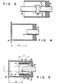
- Fig. 3 is an enlarged view of portion “A" of Fig. 1.
- Fig. 4 is a sectional view of the shutter plate 15 in the "closed” position.
- a plurality of fingers 19 are mounted to a finger arm 18 of the circuit breaker 11 (Fig. 1) as a movable arm, so as to electrically connect the stationary arm 16 and the finger arm 18 through the fingers 19.
- an end part 20 of the stationary arm 16 is usually processed to have an R shape.
- the air break distance between the stationary arm 16 and the shutter plate 15 is defined as the clearance of insulation "X".
- the end part 20 of the stationary arm 16 is processed into an R shape for the purpose of achieving smooth attachment and detachment of the stationary arm 16 to the fin- g ers 19.
- rounding generally results in a reduction of the convergence of the electric field, and improvements in the utilization efficiency of the electric field and the withstand voltage characteristic
- an electrode processed in R shape has a smaller clearance of insulation "X" than that of a rod electrode which is not processed into R shape for use as the stationary arm.
- this R shape usually has a radius of about 5 to 10 mm.
- the processing in R shape of this range does not improve the withstand voltage characteristics, and reduction in the clearance of insulation "X” by processing in R shape may not be expected.
- the shutter plate 15 is at the "closed” position, the electric field converges on the end part 20 of the stationary arm so that a streamer is generated, resulting in flashover.
- a disconnect contact assembly characterized in that a movable arm reciprocally movable along the axial direction and a stationary arm to be connected or disconnected according to the reciprocal movement of the movable arm are provided, and an electric field moderating ring which is electrically connected to the stationary arm surrounds the contact end of the stationary arm.
- an open end of a cylindrical insulator 21 with bottom is closed by the grounded shutter plate 15.
- the movable arm that is, the finger arm 18 and the fingers 19 are separated from the stationary arm 16. Therefore, the shutter plate is in the "closed” condition.
- the stationary arm 16 is axially mounted through the bottom of the insulator 21 in such a manner that its projecting flange 25 is securely attached to the inner surface of the bottom of the insulator 21.
- the open end of the cylindrical insulator 21 opens to the interior of the equipment chamber 2 shown in Fig. 1.
- a metal ring 23 with an insulator coating 22 is arranged around the outer circumference of the stationary arm 16, leaving a space to allow insertion of the fingers 19 at the side of the movable arm 18 shown by the do ash line in Fig. 3.
- the insulator coating 22 of insulating material such as epoxy resin is formed on the surface of a metal ring 23.
- This metal ring 23 is mounted on the base of the stationary arm 16, that is, the projecting flange 25 of the stationary arm 16 to be electrically connected thereto. This metal ring 23 moderates the convergence"of the electric field at the end part 20 of the statinary arm.
- the clearance of insulation "X" may be reduced to about 1/2 to 1/3 its original value by forming the insulator coating 22 in a thickness of about 2 mm.
- the height h6 is defined, as shown in Fig. 5, as the height obtained when the angle 9 is 30°, this angle 9 being formed by the front end surface of the stationary arm 16 and the line connecting the center at the front end of the stationary arm 16 with the front end of the metal ring 23.
- the flashover voltage Vf becomes about twice that obtained when the ring 26 is not used. It is thus seen that the clearance of insulation "X" may be decreased to about half.
- the electric field moderating ring 26 consisting of the metal ring 23 and the insulator coating 22 was used.
- an electric field moderating ring may alternatively be used which consists of an insulator ring and a high resistance layer formed by a coating of a high resistance paint on the surface of the insulator ring.
- Fig. 7 shows the main part of an embodiment for achieving this.
- a cylindrical insulator ring 30 of an insulating material is mounted on the base 25 of the stationary arm 16 to surround the stationary arm 16.
- a high resistance layer 31 of a high resistance paint is coated on the surface of the insulator ring 30 to constitute an electric field moderating ring 32.
- resin material containing carbon and having a specific resistance of about 10 3 to 10 5 Q-cm is commercially available, and this may be used in this embodiment.
- One end of the high resistance layer 31 is coated so as to be in contact with the stationary arm 16.
- the electric field at the end part 20 of the stationary arm may be uniformly distributed due to the presence of the high resistance layer, so that the electric field acting on the end part 20 may be moderated.
- a thermally contactile high resistance tube having a specific resistance of the same order of magnitude may be arranged over the surface of the insulator ring 30.
- an electric field moderating ring 33 of a high resistance material is formed on the base 25 of the stationary arm 16.
- a resin material having a specific resistance of about 10 3 to 10 5 Q-cm may be used.
- the same material as that used for the high resistance layer 31 of Fig. 7 may be used.
- the clearance of insulation "X" may also be reduced in this manner.
- the electric field moderating ring electrically connected to the stationary arm surrounds the end part of the stationary arm of the disconnect contact assembly, the clearance of insulation "X" to the opposing grounding metal, for example the shutter plate, may be reduced.
- the enclosed switchboard may thus be made compact in size.
Landscapes
- Engineering & Computer Science (AREA)
- Power Engineering (AREA)
- Arc-Extinguishing Devices That Are Switches (AREA)
- Trip Switchboards (AREA)
Applications Claiming Priority (2)
| Application Number | Priority Date | Filing Date | Title |
|---|---|---|---|
| JP1980116034U JPS5740225U (fr) | 1980-08-18 | 1980-08-18 | |
| JP116034/80U | 1980-08-18 |
Publications (3)
| Publication Number | Publication Date |
|---|---|
| EP0046303A2 true EP0046303A2 (fr) | 1982-02-24 |
| EP0046303A3 EP0046303A3 (en) | 1982-05-12 |
| EP0046303B1 EP0046303B1 (fr) | 1984-12-12 |
Family
ID=14677100
Family Applications (1)
| Application Number | Title | Priority Date | Filing Date |
|---|---|---|---|
| EP81106410A Expired EP0046303B1 (fr) | 1980-08-18 | 1981-08-18 | Assemblage de contact pour un sectionneur |
Country Status (4)
| Country | Link |
|---|---|
| US (1) | US4476361A (fr) |
| EP (1) | EP0046303B1 (fr) |
| JP (1) | JPS5740225U (fr) |
| DE (1) | DE3167706D1 (fr) |
Cited By (2)
| Publication number | Priority date | Publication date | Assignee | Title |
|---|---|---|---|---|
| GB2173640A (en) * | 1985-04-09 | 1986-10-15 | Northern Eng Ind | Capacitive connector |
| EP0556478A1 (fr) * | 1992-02-15 | 1993-08-25 | Asea Brown Boveri Ag | Interrupteur-séparateur pour une installation de haute tension blindée de métal à isolation de gaz |
Families Citing this family (5)
| Publication number | Priority date | Publication date | Assignee | Title |
|---|---|---|---|---|
| FR2542142B1 (fr) * | 1983-03-02 | 1987-02-20 | Merlin Gerin | Interrupteur ou disjoncteur a pinces d'embrochage perfectionnees |
| US4730231A (en) * | 1985-03-04 | 1988-03-08 | Kabushiki Kaisha Meidensha | Gas insulated metal-clad high voltage equipment with insulating bushing |
| DE10025691A1 (de) * | 2000-05-24 | 2001-11-29 | Abb Patent Gmbh | Isolierstück für eine Rohrleitung |
| WO2020110059A1 (fr) * | 2018-11-30 | 2020-06-04 | Abb Schweiz Ag | Équipement de commutation doté d'un ensemble obturateur |
| CN112670118B (zh) * | 2020-12-04 | 2022-09-30 | 河南平高通用电气有限公司 | 一种环网柜用接地连锁装置和环网柜 |
Family Cites Families (15)
| Publication number | Priority date | Publication date | Assignee | Title |
|---|---|---|---|---|
| US1530365A (en) * | 1923-12-15 | 1925-03-17 | Gen Electric | Disconnecting switch |
| DE922779C (de) * | 1952-01-27 | 1955-01-24 | Siemens Ag | Vorgeschobene Elektroden bei Hochspannungsleiterverbindungen |
| DE922890C (de) * | 1952-01-27 | 1955-01-27 | Siemens Ag | Loesbare, insbesondere steckbare Verbindung von Hochspannungsleitern mit vorgeschobenen Elektroden |
| US3160727A (en) * | 1961-10-24 | 1964-12-08 | Gas-blast orifice-type interrupting unit | |
| FR1330078A (fr) * | 1962-07-31 | 1963-06-14 | Licentia Gmbh | Dispositif d'isolement pour les traversées de conduits dans des appareils à haute tension à isolant liquide |
| BE630840A (fr) * | 1963-04-10 | 1963-10-10 | Acec | Isolateur de traversee pour fixation dans une paroi verticale d’une cuve remplie d’un fluide isolant |
| US3542943A (en) * | 1969-02-07 | 1970-11-24 | Westinghouse Electric Corp | Water tight connector bushing for capacitor units |
| JPS4869068A (fr) * | 1971-12-22 | 1973-09-20 | ||
| JPS4869069A (fr) * | 1971-12-22 | 1973-09-20 | ||
| JPS5232530A (en) * | 1975-09-05 | 1977-03-11 | Hitachi Ltd | Connecting process of lead wire for electric equipment |
| FR2344987A1 (fr) * | 1976-03-15 | 1977-10-14 | Merlin Gerin | Sectionneur de mise a la terre pour poste blinde a haute tension |
| US4104497A (en) * | 1976-08-30 | 1978-08-01 | General Electric Company | Disconnect contact assembly for metal-clad switchgear and the like |
| DE2704385B2 (de) * | 1977-01-31 | 1979-10-04 | Siemens Ag, 1000 Berlin Und 8000 Muenchen | Trennschalter für metallgekapselte Hochspannungsschaltanlagen |
| US4249049A (en) * | 1977-12-19 | 1981-02-03 | Electric Power Research Institute, Inc. | High voltage plain break circuit interrupter |
| US4175815A (en) * | 1978-05-31 | 1979-11-27 | Amerace Corporation | Connector element with means for reducing effects of radial void in electrical connection |
-
1980
- 1980-08-18 JP JP1980116034U patent/JPS5740225U/ja active Pending
-
1981
- 1981-08-17 US US06/293,236 patent/US4476361A/en not_active Expired - Fee Related
- 1981-08-18 EP EP81106410A patent/EP0046303B1/fr not_active Expired
- 1981-08-18 DE DE8181106410T patent/DE3167706D1/de not_active Expired
Cited By (3)
| Publication number | Priority date | Publication date | Assignee | Title |
|---|---|---|---|---|
| GB2173640A (en) * | 1985-04-09 | 1986-10-15 | Northern Eng Ind | Capacitive connector |
| GB2173640B (en) * | 1985-04-09 | 1989-10-04 | Northern Eng Ind | Capacitor arrangement for electricity supply control systems |
| EP0556478A1 (fr) * | 1992-02-15 | 1993-08-25 | Asea Brown Boveri Ag | Interrupteur-séparateur pour une installation de haute tension blindée de métal à isolation de gaz |
Also Published As
| Publication number | Publication date |
|---|---|
| DE3167706D1 (en) | 1985-01-24 |
| EP0046303B1 (fr) | 1984-12-12 |
| JPS5740225U (fr) | 1982-03-04 |
| EP0046303A3 (en) | 1982-05-12 |
| US4476361A (en) | 1984-10-09 |
Similar Documents
| Publication | Publication Date | Title |
|---|---|---|
| CA1073982A (fr) | Connecteur electrique separable a interface a graduation de tension mecanique | |
| US4846724A (en) | Shielded cable assembly comprising means capable of effectively reducing undesirable radiation of a signal transmitted through the assembly | |
| US2323399A (en) | Spark plug shield | |
| JP6811905B1 (ja) | ガス絶縁開閉装置 | |
| US6075209A (en) | Insulated cap for loadbreak bushing | |
| USRE28604E (en) | Gas shield for load-break cable terminations | |
| US5578804A (en) | Metal-enclosed gas-insulated switching installation | |
| US4476361A (en) | Disconnect contact assembly | |
| CA2105043A1 (fr) | Composants et systemes electroniques utilisant la technologie des cables coaxiaux | |
| US4700270A (en) | Metal-encapsulated gas-insulated switching system | |
| EP0049642B1 (fr) | Appareil électrique isolé aux gaz | |
| US4730231A (en) | Gas insulated metal-clad high voltage equipment with insulating bushing | |
| JPH1023620A (ja) | 電界緩和装置 | |
| CN112421467A (zh) | 一种带隔离开关的电压互感器柜 | |
| JP3712456B2 (ja) | ガス絶縁断路器 | |
| JP3897972B2 (ja) | 電気機器のケーブル終端接続構造 | |
| CN213937192U (zh) | 一种带隔离开关的电压互感器柜 | |
| US3710247A (en) | Cable terminal for high voltage cables | |
| JP3585517B2 (ja) | ガス絶縁ブッシング | |
| CA3179760C (fr) | Commutateur isole a l'air comprenant une longueur d'espace tres compacte | |
| GB2230143A (en) | Electrical power vacum interrupters | |
| JP2897878B2 (ja) | 電気機器の絶縁構造 | |
| JP2772094B2 (ja) | 絶縁ガス中のバリア | |
| CA2227017C (fr) | Capuchon isolant de traversee a rupture de charge | |
| JPH0393417A (ja) | ガス絶縁電気機器の絶縁構造 |
Legal Events
| Date | Code | Title | Description |
|---|---|---|---|
| PUAI | Public reference made under article 153(3) epc to a published international application that has entered the european phase |
Free format text: ORIGINAL CODE: 0009012 |
|
| 17P | Request for examination filed |
Effective date: 19810818 |
|
| AK | Designated contracting states |
Designated state(s): DE GB |
|
| PUAL | Search report despatched |
Free format text: ORIGINAL CODE: 0009013 |
|
| AK | Designated contracting states |
Designated state(s): DE GB |
|
| RAP1 | Party data changed (applicant data changed or rights of an application transferred) |
Owner name: KABUSHIKI KAISHA TOSHIBA |
|
| GRAA | (expected) grant |
Free format text: ORIGINAL CODE: 0009210 |
|
| AK | Designated contracting states |
Designated state(s): DE GB |
|
| REF | Corresponds to: |
Ref document number: 3167706 Country of ref document: DE Date of ref document: 19850124 |
|
| PLBE | No opposition filed within time limit |
Free format text: ORIGINAL CODE: 0009261 |
|
| STAA | Information on the status of an ep patent application or granted ep patent |
Free format text: STATUS: NO OPPOSITION FILED WITHIN TIME LIMIT |
|
| 26N | No opposition filed | ||
| REG | Reference to a national code |
Ref country code: GB Ref legal event code: 746 |
|
| PG25 | Lapsed in a contracting state [announced via postgrant information from national office to epo] |
Ref country code: GB Free format text: LAPSE BECAUSE OF NON-PAYMENT OF DUE FEES Effective date: 19880818 |
|
| PG25 | Lapsed in a contracting state [announced via postgrant information from national office to epo] |
Ref country code: DE Effective date: 19890503 |
|
| GBPC | Gb: european patent ceased through non-payment of renewal fee |