EP0046312A2 - Ensemble von Schmuckgegenständen - Google Patents
Ensemble von Schmuckgegenständen Download PDFInfo
- Publication number
- EP0046312A2 EP0046312A2 EP81200743A EP81200743A EP0046312A2 EP 0046312 A2 EP0046312 A2 EP 0046312A2 EP 81200743 A EP81200743 A EP 81200743A EP 81200743 A EP81200743 A EP 81200743A EP 0046312 A2 EP0046312 A2 EP 0046312A2
- Authority
- EP
- European Patent Office
- Prior art keywords
- frame
- slide
- support
- female
- male
- Prior art date
- Legal status (The legal status is an assumption and is not a legal conclusion. Google has not performed a legal analysis and makes no representation as to the accuracy of the status listed.)
- Granted
Links
Images


Classifications
-
- A—HUMAN NECESSITIES
- A44—HABERDASHERY; JEWELLERY
- A44C—PERSONAL ADORNMENTS, e.g. JEWELLERY; COINS
- A44C17/00—Gems or the like
- A44C17/02—Settings for holding gems or the like, e.g. for ornaments or decorations
- A44C17/0208—Settings for holding gems or the like, e.g. for ornaments or decorations removable
-
- A—HUMAN NECESSITIES
- A44—HABERDASHERY; JEWELLERY
- A44C—PERSONAL ADORNMENTS, e.g. JEWELLERY; COINS
- A44C13/00—Connectible jewellery
Definitions
- the present invention relates to improvements to articles of jewelry intended to be worn by a person. It relates more particularly to sets of objects of jewelry comprising a series of supports of different natures and / or dimensions and one or more mounts provided with identical receptacles.
- support designates a ring to be worn on the finger, a bracelet, an earring, a brooch, a cufflink, a pendant bail, a hairpin. tie, hairpin and, in general, any similar object used for finery.
- frame designates a part intended to be associated with a support to constitute a jewel.
- This frame can be decorated with at least one ornament or ornamental element which can possibly consist of a decorative motif, such as, for example, initials, a coat of arms, etc., or can carry at least one precious stone. or not, possibly cut, in a natural mineral material or a synthetic material, for example diamond, sapphire, emerald, ruby, turquoise, opal, jade, onyx, coral, pearl natural or synthetic, etc.
- the frame consists of a basket known per se, intended to hold the stones in place by crimping.
- receptacle As used in the present specification, it designates a part intended to be fixed permanently to the frame, to help make this frame removable.
- Rings comprising a ring and a basket supporting precious stones or not.
- a ring During its manufacture, a ring generally consists of two main parts, namely, on the one hand, a ring and, on the other hand, a basket in which the stones are set. These two parts are then welded and the assembly is subjected to finishing work. For reasons of solidity and aesthetics, the height of the ring is often greater at the welding points, although certain models of ring are cast in one piece.
- the ring When the ring is put on sale, the ring must be matched with the buyer's finger. This measurement calculated in millimeters of finger circumference can be very variable and is generally between 45 and -65 mm. To measure, you have to cut the ring, deform it, remove or add metal as necessary, reshape it, resolder it, polish it and rhodium it again.
- sets of objects of jewelry comprising a series of supports and at least one frame provided with a receptacle, which can be coupled to each other interchangeably.
- US Patent No. 3,133,331 describes a device for fixing a mount receptacle to a support, such as a ring or a chain.
- This fixing device consists of two parts, namely a clasp secured to the dorsal face of a frame and a block secured to the support.
- the clasp has the shape of a U which is welded by its base to the dorsal face of the frame and of which a first wing carries a pivot on which is mounted a pivoting tab with tabs, while the second wing is perforated and provided with 'a retaining element, so as to retain the tabs of the aforementioned tab, when the latter has been caused to pivot towards the second wing of the clasp.
- the block secured to the support has an opening extending from one face to the opposite face of the block, so that it can be threaded onto the pivoting tab of the clasp.
- the block carried by the support is threaded on the raised tab of the clasp, after which the pivot is pivoted 90 ° in the sinistrorsum direction towards the second wing. of the clasp, until the tabs of said tab are gripped by the retaining element of said second wing of the clasp.
- the clasp and the block forming the fastening device are visible since they are located outside the frame. This constitutes, from an aesthetic point of view, a particularly unwelcome drawback in the case of a jewel.
- the device for suspending the frame from the chain which is located in the center of the back plane of the frame, is also very unreliable and the pendant is completely unbalanced. in its service position.
- the frame carries a pivot of a lever whose free end can be hooked to the frame in its closed position, in which this lever extends perpendicular to the median plane of the ring, while being engaged in a groove open towards the center of the ring.
- This groove is formed by an inverted U-shaped part of the ring, the width of this groove being just sufficient to allow the lever to pass through it when it is in the closed position.
- the ring also has, on either side of the grooved portion in the shape of an inverted U, a projection which is received in a hole in the frame.
- the subject of the invention is sets of articles of jewelry, in which the means of coupling between a given frame and any support of the series of supports are such that they are entirely hidden in the frame , so that the jewel has the appearance of a normal jewel in which the frame is secured to a support, without being able to be accidentally uncoupled therefrom.
- the present invention therefore relates to a set of articles of jewelry, comprising a series of supports of different natures and / or dimensions and at least one frame fitted with an ornamental element on a front face and which can be coupled by its dorsal face to any support of the aforementioned series, male and female means for coupling the frame or each frame to a support, as well as a lever for blocking the male and female elements in their state of coupling, this assembly being essentially characterized in that the female element of the coupling means is housed and fixed permanently inside the or each frame and in that this female element has a slide which is open in the dorsal side of the frame and opens into two opposite faces of the female element, the cross section of this slide having at least a part wider than the opening of the slide, while the male element coupling means which is part of a support comprises a part of a shape complementary to that of the slide, in such a way that, when this part of the male element has been engaged in the slide of the female element, it either impossible-to extract the male element from the female
- the locking lever is carried, at one end, by a pivot subject to the female element of the coupling means and has, in the vicinity of its opposite end, means for gripping a boss of the female element housed inside the or each frame.
- the lever advantageously extends substantially in the plane of the dorsal face of the or each frame and is preferably embedded in a groove made in the face of the female element of the coupling means, which is coplanar with the dorsal face of said female element, said groove being advantageously substantially perpendicular to the opening of the slide of the female element in this dorsal face of the frame.
- the female element is constituted by a receptacle having dimensions such that it can be housed and fixed permanently inside each frame, so that its face in which the slide opens is substantially coplanar with the dorsal side of the or each frame.
- each support in the series of supports it has, according to an important feature of the invention, a cutout intended to allow passage to the locking lever when the latter is in its service position, this cutout being made in the part of the support engaged in the slide of the female element housed in the or each mount.
- the male element which is substantially the same for each of the supports of the series of supports and which is part of each support comprises, according to the invention, a part of shape corresponding to that of the part of the slide, which is wider that the opening of this slide, as well as a narrower part of shape corresponding to that of the part of the slide in which the opening of this slide is formed, which opens into the dorsal face of the or each frame.
- each support is constituted by a projection formed, preferably, of a plate integral with each support.
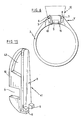
- Figures.1 and 2 show a support designated, generally, by the reference notation 2 and consisting of a ring which is integral with a male coupling element having a projection 3 in the form of wafer or tablet.
- the plate 3 On its upper face 4, the plate 3 carries, at one end 5, two stops 6 which serve to stop a female coupling element housed in a mount, when this female element is slid into the male element. Instead of being carried by the upper face 4 of the wafer 3, the stops 6 can be carried by the lower face 11 of this. plate 3.
- the end 7 opposite the end 5 of the plate 3 forming a part of the male coupling element tapers or is bevelled as shown in 8 to facilitate its insertion into a female coupling element housed in a mount.
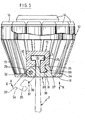
- the frame generally designated by the reference notation 12 is constituted, for example, by a basket 13 (see in particular FIGS. 3, 5, 19 to 23) with claws between which one or more precious stones 14 are set, such as brilliants (see Figures 5 and 19 to 23).
- the dorsal face 16 of this female coupling element 15 is coplanar with the dorsal face 17 of the basket 13 forming the mount 12, so that this female coupling element 15 is entirely housed in the mount 12.
- the female coupling element 15 is provided with a slide 18 which has an opening 19 towards the dorsal face 16 of the female element 15 and which opens into two opposite faces 20 and 21 of this element 15.
- the cross section of the slide 18 has, in the embodiment shown in Figures 3 and 5, at least one part 22 wider than the opening 19, so that when the male element (part 10 and plate 3) is engaged in the slide 18 of the female coupling element 15, it is impossible to extract the male element in question from the female element 15 through the opening 19 thereof, which opens into its dorsal face 16, in the direction of arrows X.
- the male coupling element (part 10 and plate 3) integral with the support 2 and the slide 18 of the female coupling element 15 have a substantially T-shaped section
- the plate 3 can optionally be provided with means such as lateral grooves formed in the wings of this plate, so as to allow adjustment of the friction between this plate 3 and the slide 18, by relative deformation of these wings.
- the female coupling element or receptacle 15 is in the form of a rectangular parallelepiped, but it can have any other suitable shape allowing it to be permanently housed inside a frame, such as a basket with precious stones or not.
- the female coupling element 15 When the female coupling element 15 is in place on the male coupling element 10, 3, the latter is inserted into the slide 18 of the female coupling element with some friction.
- the upper face 4, the lateral faces 23, 24 and a part of the lower face 11 of the plate 3 are in contact with the internal wall 25 of the wide part 22 of the slide 18 with a certain friction making it possible to slide.
- the female coupling element 15 on the plate 3 and the part 10 of the male coupling element either to place it on this male coupling element as indicated by the arrow Y, or for the remove in the opposite direction to this arrow Y (figure 6).
- the female coupling element or receptacle 15 has along a lower edge two ears 26 each pierced with a horizontal hole 27 of circular section and separated from each other by a groove 28.
- the horizontal holes 27 ears 26 serve to allow passage to a rod 29 constituting the pivot of a locking lever designated as a whole by the reference notation 30.
- the rod forming pivot 29 can be fixed or can be rotatable in the holes 27.
- the lever 30 In the groove 28 separating the two ears 26 extends, in the service position, the lever 30 which can pivot in the direction of the arrows Z (see FIG. 5) around the pivot 29.
- a hole 33 giving way to the rod forming a pivot 29.
- the lever 30 At its end 34 opposite its end 32, the lever 30 has a flange 35 directed upwards.
- the flange 35 overlaps, for example by clicking, a bead 36 of the female coupling element 15, so that the lever 30, the part of which passes through cutout 9 of the part 10 of the support, is held in the closed position by the bead 36 and thus constitutes a locking means preventing the mount 12 from accidentally detaching from the support 2.
- the lever 30 comprises, in the vicinity of its end 32, on its upper face 38, a boss 39 of a shape such that the frame 12 cannot be released from the support 2 until the lever 30 has pivoted. more than 90 ° (as shown in broken lines) from its locked position to its open position.
- FIG. 5 also shows a grip tab 37 provided at the free end 34 of the lever 30.
- the lever 30 occupies, in its locking position, a position such that it is embedded in the female coupling element 15 which is itself mounted inside the frame. 12.
- the locking lever 30, which passes through the cutout 9 formed in the part 10 of the support extending below the wafer 3, practically does not protrude relative to the dorsal face 16 of the female coupling element 15, this dorsal face 16 itself being coplanar with the dorsal face 17 of the basket 13 forming the frame 12.
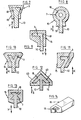
- FIGS. 7 to 13 schematically represent, by way of illustrative and nonlimiting examples, various shapes which the male coupling elements 3, 10 and the corresponding female coupling elements 15 of the mounts 12 can have.
- the plate 3, as well as the corresponding part of the slide 18 of the female coupling element 15 are widened upwards, that is to say that they have a cross section trapezoidal, while in Figures 3 and 5, these elements have the shape of a T in cross section.
- FIG. 8 shows a plate 3 and a corresponding part of the slide 18 of cylindrical shape having a diameter greater than the width of the opening 19 of said slide 18.
- the plate 3 is simply constituted by a tablet secured along one of its sides to the part 10 of the support 2, while the slide 18 of the female coupling element 15 secured to the mount 12 has a substantially inverted L shape.
- FIG. 10 shows a plate 3 formed of two oblique shelves integral with the part 10 integral with the support 2, the slide 18 of the female coupling element 15 having a complementary Y shape.
- a male coupling element 3 having an oblique branch integral with the part 10 of the support 2 and a horizontal branch integral with the oblique branch.
- the slide 18 of the female coupling element 15 has a corresponding shape.
- FIG. 12 shows an arrangement in which the slide 18 of the female coupling element 15 has the shape of an arrow having an upper surface 40 formed by two inclined faces.
- the male coupling element (plate 3 and part 10) of the support 2 also has the shape of an arrow in cross section.
- the projection or plate 3 of the support 2 (ring) has a width greater than that of its base or lower part 10 integral with this support 2, while the slide 18 of the female coupling element has a corresponding greater width in the vicinity of the bottom of said slide than at its inlet opening 19.
- the various shapes of the male coupling elements 3, 10 and of the slides 18 of the female coupling elements 15 shown in the drawings prevent the mounting 12 from being separated from the support 2, when it is mounted in this support 2, in one direction vertical (when considering the drawings), that is to say in the direction of the arrows X.
- the female coupling element 15 has a cross section of which at least part is an angle less than 180 ° with their remaining part (see figures 7, 9, 10, 11 and 12). Thus, a traction exerted on a frame 12 in the direction of the arrows X does not make it possible to separate this frame from the support 2.
- the projection or plate 3 integral with the part 10 of the support 2 has a shape such that, when it is engaged in the slide 18 of corresponding shape of the female coupling element 15 housed in the mount 12, the latter can only be separated from the plate 3 in one direction, namely that opposite to the direction of the arrow Y in FIG. 6.
- This direction corresponds to a longitudinal axis of the plate 3 and the enlarged part of the slide 18, this axis being symbolized by the dashed lines PP in FIG. 1.
- FIG. 14 shows in perspective a female coupling element 15 having an arrow-shaped slide 18 which can be mounted on a support plate 3 similar to that illustrated in FIG. 12.
- FIG. 15 shows, in perspective, a bail of a pendant that can be subjected to a chain or necklace (not shown).
- the bail designated as a whole by the reference notation 41 has a part 10 in which is provided an eyelet 42 intended to allow passage to a chain or a necklace and a part 3 integral with part 10, two stops 6 being provided at the end of part 3.
- parts 10 and 3 have the shape of a T and constitute a male coupling element.
- a cutout 9 On this bail 41 can be slid and blocked the female coupling element 15 housed in a mount 12, as indicated in the various embodiments described above.
- a mount 12 in which is housed a female coupling receptacle 15 with slide 18 provided with a locking lever 30 of the type shown in FIG. 4 or in FIG. 5 allows to block a mount on the bail 41.
- FIG. 16 shows an earring comprising a rod 43, one end of which has a notch 44 intended to receive a stop piece (not shown).
- the male coupling element comprising a part 10 serving to support a plate 3, for example of the type illustrated in FIG. 1, this plate carrying stops 6 on its underside 11 adjacent to room 10.
- a female coupling element 15 for example of the type shown in Figure 3 housed in a mount 12, locking means, such as a lever 30 of the type shown in FIG. 4 or in FIG. 5, being used to prevent the frame 12 from accidentally detaching from the part 10 and from the plate 3.
- FIG. 17 shows a bracelet 45 (partially shown) carrying a part 10, of which a plate 3 may be of the type shown in FIG. 1.
- This plate 3 and the part 10 are intended to be engaged in the slide 18 of a female coupling receptacle 15 mounted inside a mount, for example, similar to that designated by the reference notation 12 in Figures 3, 5 and 6.
- the mount 12 carries a locking member, such as a lever, passing through an opening 46 made in part 10.
- FIG. 18 represents a pin or a tie pin on which a mount can be adapted by means of a female coupling element 15 with slide 18 fixed in this mount.
- This pin or pin consists of a tapered rod 47, one end of which carries a part 10 and a plate 3 similar to those designated by the same reference numbers, in particular in FIG. 1.
- a mount 12 for example of the type illustrated in FIGS. 3, 5 and 6, is slid in, a locking lever 30 being provided to keep the mount 12 secured to the wafer 3 by fitting into the cutout 9, while allowing the removal of this mount. by disabling the locking lever 30.
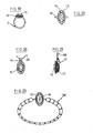
- Figures 19 to 23 show that one can use the same frame 12 having a basket 13 in which are set gemstones 14 on a support consisting of a ring 2 ( Figure 19), a bail 41 pendant chain 48 ( Figures 20 and 21), a brooch or pin bar 49 ( Figure 22) and a bracelet 50 (Figure 23).
- FIGS. 1 to 24 show various embodiments of the invention drawn on a large scale for clarity of illustration and the components of which can be combined or combined differently.
- the system according to the invention makes it possible to connect, in a removable and interchangeable manner, the same mount in which is housed a female element or receptacle to various supports of different sizes and / or types, reliably, without affecting the aesthetic appearance of the jewelry.
- the fastening and locking systems provided in accordance with the invention are, in fact, extremely reliable and easy and quick to handle.
- the solidity and the aesthetic character of the articles of jewelry according to the invention are perfectly comparable to those of articles of jewelry or jewelry made according to traditional techniques.
Landscapes
- Adornments (AREA)
- Telephone Function (AREA)
Priority Applications (1)
| Application Number | Priority Date | Filing Date | Title |
|---|---|---|---|
| AT81200743T ATE10800T1 (de) | 1980-08-20 | 1981-07-01 | Ensemble von schmuckgegenstaenden. |
Applications Claiming Priority (2)
| Application Number | Priority Date | Filing Date | Title |
|---|---|---|---|
| BE0/201799A BE884842A (fr) | 1980-08-20 | 1980-08-20 | Perfectionnements aux objets de bijouterie ou de joaillerie |
| BE201799 | 1980-08-20 |
Publications (3)
| Publication Number | Publication Date |
|---|---|
| EP0046312A2 true EP0046312A2 (de) | 1982-02-24 |
| EP0046312A3 EP0046312A3 (en) | 1982-03-03 |
| EP0046312B1 EP0046312B1 (de) | 1984-12-19 |
Family
ID=3843355
Family Applications (1)
| Application Number | Title | Priority Date | Filing Date |
|---|---|---|---|
| EP81200743A Expired EP0046312B1 (de) | 1980-08-20 | 1981-07-01 | Ensemble von Schmuckgegenständen |
Country Status (7)
| Country | Link |
|---|---|
| US (1) | US4393667A (de) |
| EP (1) | EP0046312B1 (de) |
| JP (1) | JPS5935605B2 (de) |
| AT (1) | ATE10800T1 (de) |
| BE (1) | BE884842A (de) |
| DE (1) | DE3167818D1 (de) |
| ES (1) | ES262191Y (de) |
Cited By (5)
| Publication number | Priority date | Publication date | Assignee | Title |
|---|---|---|---|---|
| FR2535587A1 (fr) * | 1982-11-05 | 1984-05-11 | Bon Mardion Simone | Bijou transformable |
| GB2137071A (en) * | 1983-03-21 | 1984-10-03 | Mary Agnes Jenkins | Article of personal adornment |
| WO1986004696A1 (fr) * | 1985-02-05 | 1986-08-14 | Victor Alexander Milles | Procede de fabrication de pieces de bijouterie ou de montres-bracelets |
| FR2615077A1 (fr) * | 1987-05-13 | 1988-11-18 | Chaput Alain | Element de bijou a montage rapide |
| FR2814043A1 (fr) * | 2000-09-18 | 2002-03-22 | Michel Paul Jacques Lumet | Bijou a decor interchangeable |
Families Citing this family (16)
| Publication number | Priority date | Publication date | Assignee | Title |
|---|---|---|---|---|
| JPS61128305U (de) * | 1985-01-30 | 1986-08-12 | ||
| US4974429A (en) * | 1989-05-25 | 1990-12-04 | Ferrara Carl J | Combined bracelet and pendant |
| US5011240A (en) * | 1989-11-28 | 1991-04-30 | Milcare, Inc. | Segmented side wall cart |
| US5133195A (en) * | 1990-06-29 | 1992-07-28 | Stephen Appelbaum | Ornamental jewelry system |
| US5357770A (en) * | 1992-04-10 | 1994-10-25 | Lanyi Carolyn H | Jewelry with interchangeable ornamental members |
| GB2304535A (en) * | 1995-09-09 | 1997-03-26 | Martins The Jewellers Limited | An article of jewellery |
| US6701747B2 (en) | 2001-10-18 | 2004-03-09 | Heart & Company | Decorative articles with interchangeable modules |
| US7055342B2 (en) * | 2001-11-13 | 2006-06-06 | Leon Minassian | Jewelry with hour of day reminder mechanism |
| US6729159B2 (en) * | 2002-07-16 | 2004-05-04 | Laura Jeanene Rose | Interchangeable jewelry system |
| US6715314B2 (en) * | 2002-07-26 | 2004-04-06 | Laura Jeanene Rose | Interchangeable ring system |
| US7143607B2 (en) * | 2003-08-27 | 2006-12-05 | Heart & Company | Jewelry article having interchangeable setting and capture module |
| US9021835B2 (en) | 2010-04-05 | 2015-05-05 | Babyak Holdings, LLC | Removable jewelry setting |
| US8434327B2 (en) | 2010-04-05 | 2013-05-07 | Babyak Holdings, LLC | Removable jewelry setting |
| US20130084412A1 (en) * | 2011-09-29 | 2013-04-04 | Garth Robert Parker | Ornamental devices with interchangeable decorative pieces |
| US9661903B2 (en) * | 2012-08-29 | 2017-05-30 | Claude Bisserier | Cross bow ring with ornament support |
| US9149094B2 (en) * | 2013-01-07 | 2015-10-06 | Meredith Marks | Adapter for ornamental accessory |
Family Cites Families (14)
| Publication number | Priority date | Publication date | Assignee | Title |
|---|---|---|---|---|
| DE620113C (de) * | 1935-10-14 | Max Wenzel | Ohrgehaenge mit bei geschlossenem Ohrring abnehmbarem Anhaenger | |
| US684272A (en) * | 1901-05-20 | 1901-10-08 | Lambert Brothers | Finger-ring. |
| US774781A (en) * | 1904-08-10 | 1904-11-15 | Untermeyer Robbins Company | Finger-ring. |
| US984682A (en) * | 1909-09-09 | 1911-02-21 | Hermann H Lott | Interchangeable head for jewelry. |
| US2316225A (en) * | 1941-04-22 | 1943-04-13 | Hoffmann Elisa Strajman De De | Ring-mounted jewelry |
| US2578507A (en) * | 1949-01-27 | 1951-12-11 | Hickok Mfg Co Inc | Ornamental necktie clasp |
| FR1150077A (fr) * | 1956-04-26 | 1958-01-07 | Motif de bijouterie à montures multiples | |
| US2914928A (en) * | 1957-03-18 | 1959-12-01 | Eunice I Warden | Earring with oscillating ornament support |
| US3192737A (en) * | 1961-05-04 | 1965-07-06 | Palais Jewelers Inc | Ring with detachable, convertible mounting |
| FR1309798A (fr) * | 1962-01-10 | 1962-11-16 | Pince à cravate | |
| US3133331A (en) * | 1963-04-08 | 1964-05-19 | Marticorena Gaston | Snap-lock device for interchanging jewelry |
| FR2038504A5 (de) * | 1969-03-18 | 1971-01-08 | Lafage Pierre | |
| FR2133013A5 (de) * | 1971-04-06 | 1972-11-24 | Devinoy Et Palisson | |
| US3813732A (en) * | 1971-06-11 | 1974-06-04 | B Seavey | Detachable, convertible cuff link |
-
1980
- 1980-08-20 BE BE0/201799A patent/BE884842A/fr not_active IP Right Cessation
- 1980-10-13 ES ES1980262191U patent/ES262191Y/es not_active Expired
-
1981
- 1981-06-09 US US06/271,875 patent/US4393667A/en not_active Expired - Fee Related
- 1981-06-30 JP JP56103889A patent/JPS5935605B2/ja not_active Expired
- 1981-07-01 EP EP81200743A patent/EP0046312B1/de not_active Expired
- 1981-07-01 AT AT81200743T patent/ATE10800T1/de not_active IP Right Cessation
- 1981-07-01 DE DE8181200743T patent/DE3167818D1/de not_active Expired
Cited By (6)
| Publication number | Priority date | Publication date | Assignee | Title |
|---|---|---|---|---|
| FR2535587A1 (fr) * | 1982-11-05 | 1984-05-11 | Bon Mardion Simone | Bijou transformable |
| GB2137071A (en) * | 1983-03-21 | 1984-10-03 | Mary Agnes Jenkins | Article of personal adornment |
| WO1986004696A1 (fr) * | 1985-02-05 | 1986-08-14 | Victor Alexander Milles | Procede de fabrication de pieces de bijouterie ou de montres-bracelets |
| US4817064A (en) * | 1985-02-05 | 1989-03-28 | Milles Victor A | Structure for fabricating jewelry parts or wrist watches |
| FR2615077A1 (fr) * | 1987-05-13 | 1988-11-18 | Chaput Alain | Element de bijou a montage rapide |
| FR2814043A1 (fr) * | 2000-09-18 | 2002-03-22 | Michel Paul Jacques Lumet | Bijou a decor interchangeable |
Also Published As
| Publication number | Publication date |
|---|---|
| EP0046312A3 (en) | 1982-03-03 |
| JPS5745805A (en) | 1982-03-16 |
| ES262191U (es) | 1983-01-01 |
| EP0046312B1 (de) | 1984-12-19 |
| BE884842A (fr) | 1981-02-20 |
| DE3167818D1 (en) | 1985-01-31 |
| ES262191Y (es) | 1983-07-01 |
| JPS5935605B2 (ja) | 1984-08-29 |
| ATE10800T1 (de) | 1985-01-15 |
| US4393667A (en) | 1983-07-19 |
Similar Documents
| Publication | Publication Date | Title |
|---|---|---|
| EP0046312A2 (de) | Ensemble von Schmuckgegenständen | |
| US20150075219A1 (en) | Jewelry item, method of manufacturing a closure for jewelry item, finding for an earring, kit of parts forming the finding, and earring constructed from the kit | |
| EP4087439B1 (de) | Schmuckstück mit einer kette mit klammer zur vielseitigen verzierung | |
| FR2692763A1 (fr) | Fermoir pour objets de joaillerie-bijouterie tels que bracelets, colliers. | |
| EP0161182B1 (de) | Verschluss mit auswechselbarer Verzierung | |
| WO2012153014A1 (fr) | Bijou ou accessoire vestimentaire à mécanisme de déplacement de pierre | |
| EP4061179A1 (de) | Schmuckstück mit einer spange | |
| CH649454A5 (en) | Ear jewel | |
| FR2679741A1 (fr) | Fermoir pour chaine de perles. | |
| EP4018875A1 (de) | Armband | |
| FR2662058A1 (fr) | Bijou dont l'element decoratif, pierre fine ou autres elements decoratifs, peut etre monte amovible sur son support. | |
| FR2715541A1 (fr) | Bijou à élément décoratif amovible et interchangeable. | |
| CH687575A5 (fr) | Bague à anneaux multiples. | |
| WO2010010182A1 (fr) | Ensemble de bijoux composé d'au moins trois pièces solidarisées entre elles | |
| FR2523416A1 (fr) | Monture de bijou pour la mise en valeur d'un objet decoratif tel qu'une monnaie ou medaille | |
| FR2595925A1 (fr) | Bijou comme une bague, boucle d'oreille ou analogue a pierre interchangeable | |
| CH700663B9 (fr) | Article d’ornement. | |
| FR2747277A1 (fr) | Dispositif de montage d'au moins un medaillon sur une monture de collier et collier obtenu | |
| EP0577494A1 (de) | Demontierenbares Schmuckstück | |
| FR2692764A1 (fr) | Fermoir pour colliers, bracelets ou similaires. | |
| FR2655246A1 (fr) | Bijou, notamment bracelet ou bracelet-montre, constitue par l'assemblage d'elements modulaires emboites les uns dans les autres ainsi que procede de fabrication d'un tel bijou. | |
| EP3387942B1 (de) | Schmuckartikel | |
| CH696183A5 (fr) | Bijou modulable. | |
| WO2001070068A1 (fr) | Piece ornamental avec partie amovible | |
| FR3154905A1 (fr) | Boucle d'oreille |
Legal Events
| Date | Code | Title | Description |
|---|---|---|---|
| PUAI | Public reference made under article 153(3) epc to a published international application that has entered the european phase |
Free format text: ORIGINAL CODE: 0009012 |
|
| PUAL | Search report despatched |
Free format text: ORIGINAL CODE: 0009013 |
|
| AK | Designated contracting states |
Designated state(s): AT CH DE FR GB IT LU NL SE |
|
| AK | Designated contracting states |
Designated state(s): AT CH DE FR GB IT LU NL SE |
|
| 17P | Request for examination filed |
Effective date: 19820805 |
|
| GRAA | (expected) grant |
Free format text: ORIGINAL CODE: 0009210 |
|
| AK | Designated contracting states |
Designated state(s): AT CH DE FR GB IT LI LU NL SE |
|
| PG25 | Lapsed in a contracting state [announced via postgrant information from national office to epo] |
Ref country code: SE Effective date: 19841219 Ref country code: NL Effective date: 19841219 Ref country code: IT Free format text: LAPSE BECAUSE OF FAILURE TO SUBMIT A TRANSLATION OF THE DESCRIPTION OR TO PAY THE FEE WITHIN THE PRESCRIBED TIME-LIMIT;WARNING: LAPSES OF ITALIAN PATENTS WITH EFFECTIVE DATE BEFORE 2007 MAY HAVE OCCURRED AT ANY TIME BEFORE 2007. THE CORRECT EFFECTIVE DATE MAY BE DIFFERENT FROM THE ONE RECORDED. Effective date: 19841219 Ref country code: AT Effective date: 19841219 |
|
| REF | Corresponds to: |
Ref document number: 10800 Country of ref document: AT Date of ref document: 19850115 Kind code of ref document: T |
|
| REF | Corresponds to: |
Ref document number: 3167818 Country of ref document: DE Date of ref document: 19850131 |
|
| NLV1 | Nl: lapsed or annulled due to failure to fulfill the requirements of art. 29p and 29m of the patents act | ||
| PG25 | Lapsed in a contracting state [announced via postgrant information from national office to epo] |
Ref country code: LU Free format text: LAPSE BECAUSE OF NON-PAYMENT OF DUE FEES Effective date: 19850731 Ref country code: LI Effective date: 19850731 Ref country code: CH Effective date: 19850731 |
|
| PLBE | No opposition filed within time limit |
Free format text: ORIGINAL CODE: 0009261 |
|
| STAA | Information on the status of an ep patent application or granted ep patent |
Free format text: STATUS: NO OPPOSITION FILED WITHIN TIME LIMIT |
|
| 26N | No opposition filed | ||
| REG | Reference to a national code |
Ref country code: CH Ref legal event code: PL |
|
| PG25 | Lapsed in a contracting state [announced via postgrant information from national office to epo] |
Ref country code: FR Free format text: LAPSE BECAUSE OF NON-PAYMENT OF DUE FEES Effective date: 19880331 |
|
| PG25 | Lapsed in a contracting state [announced via postgrant information from national office to epo] |
Ref country code: DE Effective date: 19880401 |
|
| GBPC | Gb: european patent ceased through non-payment of renewal fee | ||
| REG | Reference to a national code |
Ref country code: FR Ref legal event code: ST |
|
| PG25 | Lapsed in a contracting state [announced via postgrant information from national office to epo] |
Ref country code: GB Free format text: LAPSE BECAUSE OF NON-PAYMENT OF DUE FEES Effective date: 19881118 |