EP0046399A1 - Optischer Linienabtaster - Google Patents
Optischer Linienabtaster Download PDFInfo
- Publication number
- EP0046399A1 EP0046399A1 EP81303742A EP81303742A EP0046399A1 EP 0046399 A1 EP0046399 A1 EP 0046399A1 EP 81303742 A EP81303742 A EP 81303742A EP 81303742 A EP81303742 A EP 81303742A EP 0046399 A1 EP0046399 A1 EP 0046399A1
- Authority
- EP
- European Patent Office
- Prior art keywords
- array
- lens
- line
- detector
- lenses
- Prior art date
- Legal status (The legal status is an assumption and is not a legal conclusion. Google has not performed a legal analysis and makes no representation as to the accuracy of the status listed.)
- Granted
Links
Images


Classifications
-
- H—ELECTRICITY
- H04—ELECTRIC COMMUNICATION TECHNIQUE
- H04N—PICTORIAL COMMUNICATION, e.g. TELEVISION
- H04N1/00—Scanning, transmission or reproduction of documents or the like, e.g. facsimile transmission; Details thereof
- H04N1/04—Scanning arrangements, i.e. arrangements for the displacement of active reading or reproducing elements relative to the original or reproducing medium, or vice versa
- H04N1/19—Scanning arrangements, i.e. arrangements for the displacement of active reading or reproducing elements relative to the original or reproducing medium, or vice versa using multi-element arrays
- H04N1/191—Scanning arrangements, i.e. arrangements for the displacement of active reading or reproducing elements relative to the original or reproducing medium, or vice versa using multi-element arrays the array comprising a one-dimensional [1D] array
- H04N1/192—Simultaneously or substantially simultaneously scanning picture elements on one main scanning line
- H04N1/193—Simultaneously or substantially simultaneously scanning picture elements on one main scanning line using electrically scanned linear arrays, e.g. linear CCD arrays
- H04N1/1934—Combination of arrays
-
- G—PHYSICS
- G02—OPTICS
- G02B—OPTICAL ELEMENTS, SYSTEMS OR APPARATUS
- G02B26/00—Optical devices or arrangements for the control of light using movable or deformable optical elements
- G02B26/08—Optical devices or arrangements for the control of light using movable or deformable optical elements for controlling the direction of light
- G02B26/10—Scanning systems
-
- H—ELECTRICITY
- H04—ELECTRIC COMMUNICATION TECHNIQUE
- H04N—PICTORIAL COMMUNICATION, e.g. TELEVISION
- H04N1/00—Scanning, transmission or reproduction of documents or the like, e.g. facsimile transmission; Details thereof
- H04N1/04—Scanning arrangements, i.e. arrangements for the displacement of active reading or reproducing elements relative to the original or reproducing medium, or vice versa
- H04N1/19—Scanning arrangements, i.e. arrangements for the displacement of active reading or reproducing elements relative to the original or reproducing medium, or vice versa using multi-element arrays
- H04N1/191—Scanning arrangements, i.e. arrangements for the displacement of active reading or reproducing elements relative to the original or reproducing medium, or vice versa using multi-element arrays the array comprising a one-dimensional [1D] array
- H04N1/192—Simultaneously or substantially simultaneously scanning picture elements on one main scanning line
- H04N1/193—Simultaneously or substantially simultaneously scanning picture elements on one main scanning line using electrically scanned linear arrays, e.g. linear CCD arrays
- H04N1/1935—Optical means for mapping the whole or part of a scanned line onto the array
Definitions
- This invention relates to an optical scanning system and more particularly, to a system utilizing a lens array tilted at an angle with respect to an object line which projects an image of the object line onto a tiered array of linear image sensors.
- U.S. Patent 4,080,633 discloses a flying spot scanning system which utilizes a lens array tilted at an angle to a document scan line to convey the bit position information content of the document scan line onto a tiered array of light sensitive detectors disposed along an axis perpendicular to the axial direction of the scan line.
- the lens array has a lens of proper focal length associated with each scan segment of the document scan line and the detector array has a detector unit associated with each scan segment of the document scan line, with each detector unit having a detector element corresponding to each bit position of the scan segment associated with that detector unit, such that the information content of each scan segment is recorded on a different one of the tiered detector units of the detector array via a different lens of the lens array.
- a tiered or two dimensional (area) array of detector units can be utilized to record the information content of the scan line.
- area detector arrays with large numbers of detector elements more easily can be manufactured by conventional manufacturing techniques since they only require a rectangular-shaped semiconductor material wafer on the order of one inch by one quarter inch.
- the type of geometry disclosed in the above referenced patent has several characteristics which may not be appropriate for certain applications.
- the focusing requirements dictate the use of small lenses with short center-to-center spacings.
- the lens f numbers are relatively high and, to maintain radiometric efficiency, scanning speeds must be at relatively slower rates.
- a line scan optical system wherein the imaging means is a staggered double row of lenses each row having a center line on separate but parallel axis, each axis tilted with respect to the axial direction of the scan line.
- Each lens in a particular row scans alternate segments of the scan line and images these line segments onto appropriate portions of a detector imaging array.
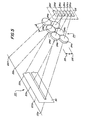
- a prior art twisted geometry optical scanning system 10. Lamps illuminate a document scan line 12.
- a flying spot scanning system (not shown but which may be a laser light beam) can scan in a conventional manner across a scan line 1.
- the document scan line is linear and may be a portion of an information-bearing document which conveys alphanumeric or facsimile information.
- the scan line can be considered to comprise a plurality of information-bearing scan segments 12a-12f of equal length.
- the portions of the scanning light beam reflected by the information-bearing segments of the scanned line are conveyed by a lens array 14 to an area array of light-sensitive detectors 16.
- the lens array 14 contains a small lens for each information-bearing segment of the scan line, as shown by lenses 14a-14f,and the area detector array 16 likewise includes a detector unit for each of the information-bearing segments of the scan line as shown by tiered detector units 16a-16f.
- the lens array 14 is disposed within a plane extending parallel to the longitudinal axis of the scan line, with the longitudinal axis 18 of the lens array 14 tilted at an angle to the longitudinal axis of the scan line.
- the lenses of lens array 14 are of appropriate focal lengths such that the information content of adjacent segments of the scan line is properly focused upon adjacent detectors of the detector array 16.
- the lens array 14 provides for projection or transmittance of the segment-wise information content of a scan line extending along a set longitudinal axis to the detector units of a detector array, which detector units are disposed along an axis which is orthogonal to the longitudinal axis of the scan line.
- the center coordinates of the image segments are generally uniformly distributed vertically along the array height. For example, with an array height H, and a total number of image segments (lenses) N, the Y-coordinate of the center of the I th image segment is located at
- the total object scan length S of object center line 12 is 356 mm.
- the object center coordinates for'each of the object segments 12a-12f is represented by an X.
- Figure 3 shows array 16 having an array height H of 1.8 mm and an array (image segment) length L of 10.38mm for each array 16a-16f.
- the Y coordinates are also represented by an X on the line representing the Y axis.
- Figure 4 shows lens array 14 as viewed from the image side with lens center-to-center distance D of 8.84mm.
- the lens object distance is 581.86mm and the image distance is 101.82mm.
- the lens center coordinates as well as values of the X and Y coordinates, are given in Table 1 below. This example requires an effective f number of f/14.4 which may be excessively high for many system applications.
- the permissible lens diameter D ' may be substantially increased (f number decreased) accompanied by an increase in radiometric efficiency.
- D' is the lens center-to-center distance for lenses in any one row.
- Figure 5 shows such a double row arrangement.
- scan line 22 of a document is again comprised of six segments 22a-22f which are scanned by a light source (not shown).
- Lens array 24 consists of six segments 24a-24f, arranged in a staggered arrangement with the centers of lenses 24b, d and f on a line 25 separated from the centers of lenses 24a, c and e on line 25' by a distance K.
- the area detector array 26 includes a detector unit 26a-26f for each of the information-bearing segments of the scanned line. However, the segments are now imaged onto different portions of the array. Referring to Figures 5 and 6, lenses 24b, d and f are of appropriate focal length such that the information content of alternating line segments 22b, d, f of the scan line are focused upon adjacent detectors 26b, d, f.
- lenses 24a, c and e project line segments 22a, c, e onto detectors 26a, c, e.
- a field stop 30 is located near the scan line to limit the y-direction extent of the individual images, as formed by each lens.
- the total height H of the array is a function of the distance K between the center lines of the two rows of lenses shown in Figure 7.
- K has been found to be ⁇ 3D'/ 2 . This value provides approximately twice the lens diameter of the previous prior art system while keeping the height of the array at approximately 20mm. Further increase in center line separation causes unnecessary growth in array height H.
- Distance G shown in Figure 6 is the separation between consecutive image segments. If the lens magnification is M, For an array height, H, and number of segments, N, the separations of adjacent segments in the top or bottom cluster is given by
- the lens coordinates may then be computed from Equation 2.
- total object scan length of line 22 is 356 mm.
- Lens object distance is 581.86mm and the image distance is 101.82mm.
- Lens center-to-center distance D' is 17.18mm and image segment length L is 10.38mm.
- Array height H 20mm, consecutive image separation G, by equation (3) is 17.984mm and S is 0.672mm (by Equation 4).
- the object, image and lens center coordinates are given in Table 2 below.
- the lens diameter has been increased to twice the diameter of the lenses in the Figure 2 embodiment. effectively halving the effective f/number. Radiometric efficiency is increased in a geometric relationship to approximately four times that of the system of Figure 2.
- Composite detector array 16 can be conveniently fabricated, using two long, thin silicon chips, each containing three linear arrays, aligned and bonded to a common substrate of slightly larger than the values of H and L above.
- An alternate method of making the array would be to fabricate six linear detectors on a single silicon chip.
Landscapes
- Engineering & Computer Science (AREA)
- Multimedia (AREA)
- Signal Processing (AREA)
- Physics & Mathematics (AREA)
- General Physics & Mathematics (AREA)
- Optics & Photonics (AREA)
- Facsimile Scanning Arrangements (AREA)
- Facsimile Heads (AREA)
Applications Claiming Priority (2)
| Application Number | Priority Date | Filing Date | Title |
|---|---|---|---|
| US179204 | 1980-08-18 | ||
| US06/179,204 US4335305A (en) | 1980-08-18 | 1980-08-18 | Twisting geometry scanner utilizing staggered lens array |
Publications (2)
| Publication Number | Publication Date |
|---|---|
| EP0046399A1 true EP0046399A1 (de) | 1982-02-24 |
| EP0046399B1 EP0046399B1 (de) | 1984-03-21 |
Family
ID=22655657
Family Applications (1)
| Application Number | Title | Priority Date | Filing Date |
|---|---|---|---|
| EP81303742A Expired EP0046399B1 (de) | 1980-08-18 | 1981-08-17 | Optischer Linienabtaster |
Country Status (4)
| Country | Link |
|---|---|
| US (1) | US4335305A (de) |
| EP (1) | EP0046399B1 (de) |
| JP (1) | JPS5767911A (de) |
| DE (1) | DE3162810D1 (de) |
Cited By (2)
| Publication number | Priority date | Publication date | Assignee | Title |
|---|---|---|---|---|
| EP0057584A3 (en) * | 1981-01-29 | 1982-08-25 | Xerox Corporation | Optical scanning apparatus |
| US5492719A (en) * | 1994-08-05 | 1996-02-20 | De Cooper Jones; Mark | Polymer matrix composite structures |
Families Citing this family (7)
| Publication number | Priority date | Publication date | Assignee | Title |
|---|---|---|---|---|
| US4970403A (en) * | 1988-11-18 | 1990-11-13 | Ltv Aerospace And Defense Company | Focal array reimaging system |
| US5581409A (en) * | 1994-09-30 | 1996-12-03 | Republic Lens Co., Inc. | Imaging system to combine disparate fields of view |
| US5789735A (en) * | 1995-10-16 | 1998-08-04 | Raytheon Company | Optical system for reformatting a line image |
| US5856888A (en) * | 1996-05-13 | 1999-01-05 | Ait Corporation | Split beam optical character reader |
| AU2003304127A1 (en) * | 2003-05-19 | 2004-12-03 | Itzhak Baruch | Optical coordinate input device comprising few elements |
| DE102013103897A1 (de) * | 2012-04-25 | 2013-10-31 | Chromasens Gmbh | Kameramodul, Produktüberwachungsvorrichtung mit einem solchen Kameramodul und Verfahren zum Abtasten eines Objektes |
| CN115629076B (zh) * | 2022-09-27 | 2025-02-18 | 威海华菱光电股份有限公司 | 一种阵列式图像检测装置 |
Citations (4)
| Publication number | Priority date | Publication date | Assignee | Title |
|---|---|---|---|---|
| US4009388A (en) * | 1975-10-30 | 1977-02-22 | Xerox Corporation | Arrangement for extending photosensor array resolution |
| DE2729358A1 (de) * | 1976-07-15 | 1978-01-19 | Xerox Corp | Lichtpunkt-abtastsystem |
| US4114037A (en) * | 1977-05-16 | 1978-09-12 | Northern Telecom Limited | Multiple lens system for an optical imaging device |
| DE2948348A1 (de) * | 1978-12-01 | 1980-06-04 | Canon Kk | Projektionseinrichtung |
Family Cites Families (1)
| Publication number | Priority date | Publication date | Assignee | Title |
|---|---|---|---|---|
| DE1203115B (de) * | 1964-11-20 | 1965-10-14 | Agfa Gevaert Ag | Belichtungsanordnung fuer Kopiergeraete |
-
1980
- 1980-08-18 US US06/179,204 patent/US4335305A/en not_active Expired - Lifetime
-
1981
- 1981-08-11 JP JP56125850A patent/JPS5767911A/ja active Pending
- 1981-08-17 EP EP81303742A patent/EP0046399B1/de not_active Expired
- 1981-08-17 DE DE8181303742T patent/DE3162810D1/de not_active Expired
Patent Citations (4)
| Publication number | Priority date | Publication date | Assignee | Title |
|---|---|---|---|---|
| US4009388A (en) * | 1975-10-30 | 1977-02-22 | Xerox Corporation | Arrangement for extending photosensor array resolution |
| DE2729358A1 (de) * | 1976-07-15 | 1978-01-19 | Xerox Corp | Lichtpunkt-abtastsystem |
| US4114037A (en) * | 1977-05-16 | 1978-09-12 | Northern Telecom Limited | Multiple lens system for an optical imaging device |
| DE2948348A1 (de) * | 1978-12-01 | 1980-06-04 | Canon Kk | Projektionseinrichtung |
Cited By (2)
| Publication number | Priority date | Publication date | Assignee | Title |
|---|---|---|---|---|
| EP0057584A3 (en) * | 1981-01-29 | 1982-08-25 | Xerox Corporation | Optical scanning apparatus |
| US5492719A (en) * | 1994-08-05 | 1996-02-20 | De Cooper Jones; Mark | Polymer matrix composite structures |
Also Published As
| Publication number | Publication date |
|---|---|
| US4335305A (en) | 1982-06-15 |
| JPS5767911A (en) | 1982-04-24 |
| DE3162810D1 (en) | 1984-04-26 |
| EP0046399B1 (de) | 1984-03-21 |
Similar Documents
| Publication | Publication Date | Title |
|---|---|---|
| US4114037A (en) | Multiple lens system for an optical imaging device | |
| US5081346A (en) | Solid state imaging device including a rod lens array | |
| US4467195A (en) | Information detecting apparatus | |
| KR101297959B1 (ko) | 화상 판독 장치 | |
| EP0046399B1 (de) | Optischer Linienabtaster | |
| US4509826A (en) | Optical image staggering/destaggering arrangement for multiple array scanning system | |
| JPH03503096A (ja) | データ表面上のデータ・ページを読出すための方法 | |
| EP0057584B1 (de) | Optischer Bildabtaster | |
| US4656517A (en) | Method for increasing resolution of array sensor and system therefor | |
| JPH0412062B2 (de) | ||
| CA1101121A (en) | Twisting geometry scanner | |
| KR100382834B1 (ko) | 기판의폭에이르는상시야에따라임의의폭을갖는렌즈어레이 | |
| US4827529A (en) | Lines and characters separation apparatus | |
| US4512632A (en) | Original reading apparatus | |
| US4141625A (en) | Optical system for multiple imaging a linear object | |
| EP0324269B1 (de) | Bildsensor mehrerer Chips | |
| JPS6276357A (ja) | 固体撮像装置 | |
| EP0070620A2 (de) | Bildaufnahmeeinrichtung mit hoher Dichte | |
| US4887139A (en) | Linear photo sensing device | |
| CA1073715A (en) | Optical system for multiple imaging of a linear object | |
| JPH11261763A (ja) | 画像読取装置 | |
| JPH0546743B2 (de) | ||
| JPS6266758A (ja) | 画像読取装置 | |
| JP3271817B2 (ja) | 光走査装置 | |
| JP2025033373A (ja) | レンズユニット、画像読取ユニット、及び画像読取装置 |
Legal Events
| Date | Code | Title | Description |
|---|---|---|---|
| PUAI | Public reference made under article 153(3) epc to a published international application that has entered the european phase |
Free format text: ORIGINAL CODE: 0009012 |
|
| AK | Designated contracting states |
Designated state(s): DE FR GB |
|
| 17P | Request for examination filed |
Effective date: 19820716 |
|
| GRAA | (expected) grant |
Free format text: ORIGINAL CODE: 0009210 |
|
| AK | Designated contracting states |
Designated state(s): DE FR GB |
|
| REF | Corresponds to: |
Ref document number: 3162810 Country of ref document: DE Date of ref document: 19840426 |
|
| ET | Fr: translation filed | ||
| PLBE | No opposition filed within time limit |
Free format text: ORIGINAL CODE: 0009261 |
|
| STAA | Information on the status of an ep patent application or granted ep patent |
Free format text: STATUS: NO OPPOSITION FILED WITHIN TIME LIMIT |
|
| 26N | No opposition filed | ||
| PGFP | Annual fee paid to national office [announced via postgrant information from national office to epo] |
Ref country code: FR Payment date: 19890613 Year of fee payment: 9 |
|
| PGFP | Annual fee paid to national office [announced via postgrant information from national office to epo] |
Ref country code: GB Payment date: 19890630 Year of fee payment: 9 |
|
| PGFP | Annual fee paid to national office [announced via postgrant information from national office to epo] |
Ref country code: DE Payment date: 19890831 Year of fee payment: 9 |
|
| PG25 | Lapsed in a contracting state [announced via postgrant information from national office to epo] |
Ref country code: GB Effective date: 19900817 |
|
| GBPC | Gb: european patent ceased through non-payment of renewal fee | ||
| PG25 | Lapsed in a contracting state [announced via postgrant information from national office to epo] |
Ref country code: FR Effective date: 19910430 |
|
| PG25 | Lapsed in a contracting state [announced via postgrant information from national office to epo] |
Ref country code: DE Effective date: 19910501 |
|
| REG | Reference to a national code |
Ref country code: FR Ref legal event code: ST |