EP0046452A2 - Appareil déchiqueteur - Google Patents
Appareil déchiqueteur Download PDFInfo
- Publication number
- EP0046452A2 EP0046452A2 EP81810336A EP81810336A EP0046452A2 EP 0046452 A2 EP0046452 A2 EP 0046452A2 EP 81810336 A EP81810336 A EP 81810336A EP 81810336 A EP81810336 A EP 81810336A EP 0046452 A2 EP0046452 A2 EP 0046452A2
- Authority
- EP
- European Patent Office
- Prior art keywords
- tooth
- clamping wedge
- wedge
- cutting knife
- flank
- Prior art date
- Legal status (The legal status is an assumption and is not a legal conclusion. Google has not performed a legal analysis and makes no representation as to the accuracy of the status listed.)
- Withdrawn
Links
- 239000000463 material Substances 0.000 description 2
- 238000004140 cleaning Methods 0.000 description 1
- 230000000694 effects Effects 0.000 description 1
- 230000002349 favourable effect Effects 0.000 description 1
- 238000004519 manufacturing process Methods 0.000 description 1
- 239000002184 metal Substances 0.000 description 1
Images



Classifications
-
- B—PERFORMING OPERATIONS; TRANSPORTING
- B02—CRUSHING, PULVERISING, OR DISINTEGRATING; PREPARATORY TREATMENT OF GRAIN FOR MILLING
- B02C—CRUSHING, PULVERISING, OR DISINTEGRATING IN GENERAL; MILLING GRAIN
- B02C18/00—Disintegrating by knives or other cutting or tearing members which chop material into fragments
- B02C18/06—Disintegrating by knives or other cutting or tearing members which chop material into fragments with rotating knives
- B02C18/16—Details
- B02C18/18—Knives; Mountings thereof
- B02C18/182—Disc-shaped knives
- B02C18/184—Disc-shaped knives with peripherally arranged demountable cutting tips or elements
-
- B—PERFORMING OPERATIONS; TRANSPORTING
- B02—CRUSHING, PULVERISING, OR DISINTEGRATING; PREPARATORY TREATMENT OF GRAIN FOR MILLING
- B02C—CRUSHING, PULVERISING, OR DISINTEGRATING IN GENERAL; MILLING GRAIN
- B02C13/00—Disintegrating by mills having rotary beater elements ; Hammer mills
- B02C13/26—Details
- B02C13/28—Shape or construction of beater elements
- B02C13/2804—Shape or construction of beater elements the beater elements being rigidly connected to the rotor
Definitions
- the invention relates to a comminution device with at least one rotating knife roller with a plurality of cutting knife sets arranged side by side, which mesh with corresponding, axially parallel, stationary or rotating cutting knife sets, the cutting knife sets of the knife roller consisting of disk-like cutting knives with exchangeable fangs, which are held in receiving slots in the cutting knife .
- Such devices are also known under the term cutting disc mill or roller crushing machine.
- the two axially parallel rollers generally rotate in opposite directions and at different speeds.
- the mutually intermeshing sets of cutting knives are provided with fangs so that the material to be shredded is torn and drawn in between the two rollers. With such devices, metal parts and tough materials can be easily shredded.
- a problem with these devices is, in particular, the extraordinarily high mechanical stress on the cutting knives or the fangs. These are also subject to relatively high wear, since they are the most stressed components. It is therefore necessary to replace the fangs after a certain number of hours of operation. An exchange is also necessary in the event of damage.
- the fangs must also be absolutely positively and non-positively stored in the cutting blades, so that no unwanted play can occur.
- a device is known from German Offenlegungsschrift No. 24 50 936, in which the fangs can be inserted laterally into the receiving slots.
- the fangs protrude freely from the disc-like cutting knife.
- a disadvantage of this arrangement is that extremely high forces occur due to the leverage effect at the base of the fangs.
- the replacement or replacement of the fangs is also very complex, since the cutting knife sets arranged next to one another have to be loosened in order to replace the fangs. It is not possible to replace individual fangs with the knife roller assembled.
- impact or hammer mills are already known from CH-PS 584 067 or FR-PS 2 340 771, in which the impact bars are fastened with wedges and can be removed radially. The wedges are locked hydraulically from the center of the roller.
- the individual, relatively narrow sets of cutting knives in a cutting disc mill cannot be compared with the long blow bars in an impact mill, so that this design principle cannot be adopted from the outset.
- cutting disc mills work with extremely high torques in contrast to impact mills, which at high speeds generate the force for comminuting an object mainly through moments of motion, mass and speed. A hydraulic determination of the Wedges are not possible with the large number of cutting knives in the cutting disc mill for cost reasons.
- Another object of the invention is to store the fangs in the cutting knife in such a way that an optimal flow of force is ensured.
- each receiving slot projects radially over the opposite flank and is designed as a support shoulder for the fang, which supports the fang at least in its radially outer region, and in that each fang with one of the Lockable wedge on the outside of the knife roller is fixed.
- each fang is supported in such a way that no unwanted torques can arise at the protruding part of the fang.
- the projecting flank also simplifies the cleaning of the cutting knife sets, since no dirt can collect behind the fangs.
- the clamping wedge tapering against the roller axis ensures in the simplest way that the wedge can be inserted from the outside and removed again.
- a particularly simple geometric shape for the production of the fangs results if each fangs has a flat end face extending in the running direction over the entire length of the fangs.
- each fang is one tangent to the plane of the cutting knife is symmetrical and if the projecting flank of the receiving slot and the side of the tearing tooth adjacent to it extend transversely to the roller axis at an obtuse angle, which is arranged in relation to the plane of symmetry such that it coincides with the bisector of the obtuse angle.
- the symmetrically designed fang has the great advantage that it can be used twice by reversing it until both sides are worn or worn.
- a similar principle is used for impact bars in impact mills, as described, for example, in Swiss Patent No. 584,067.
- the tearing tooth is mounted absolutely free of play in the radial direction when the wedge is inserted, and there is also a favorable effect of the tearing force on the cutting knife. Radially acting forces are also absorbed by the angled flank of the receiving slot or fangs. This relieves the load on the wedge, since the flank also assumes a supporting function.
- the clamping wedge extends over both sides of the plane of symmetry of the tearing tooth, the tearing tooth on both sides of the plane of symmetry is pressed approximately equally strongly against the projecting flank of the receiving slot. High contact forces can be achieved if the clamping wedge is self-locking.
- the clamping wedge has a radially running threaded hole, this hole can on the one hand receive a locking screw for the clamping wedge and on the other hand can be used to attach a pulling tool. A fixed device for removing the clamping wedge is not necessary.
- a particularly reliable wedge lock is obtained if the clamping wedge has a counter wedge that can be locked with the locking screw. This makes it possible to clamp the clamping wedge with the roller in the receiving slot without a screw connection.
- the counter wedge can also be used as an additional wedge lock in addition to another lock.
- the outside of the disk-like cutting knife can be provided with detachable segment-like covers.
- the edges of the outside serve as cutting edges and are therefore also subject to certain signs of wear.
- the segment-like covers ensure in the simplest way that a damaged cutting edge can be replaced at any point on the cutting knife. If the segment-like covers at least partially cover each clamping wedge, the clamping wedges are also secured against slipping out.
- the thickness of the segment-like covers is advantageously dimensioned in such a way that the flanks of each tear tooth projecting beyond the covers correspond approximately to the distance from the narrow end face of the clamping wedge to the outer edge lying on the side of the plane of symmetry lying against the roller axis of the flank of the tear tooth lying against the clamping wedge. Since the signs of wear on the tearing tooth can obviously only occur on the part that protrudes beyond the covers, the worn surface cannot obstruct the clamping wedge when the tipping tooth is reversed:
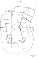
- Fig. 1 shows the silhouette of a cutting knife set 1 with a serrated tooth 3, which is held in a receiving slot 4.
- the cutting knife set has a hexagonal opening 15, so that several identical cutting knife sets can be assembled in packages to form a knife roller.
- the cutting knife set moves in the direction of arrow A.
- One side of the receiving slot 4 is extended in the radial direction in such a way that a projecting flank 5 is formed.
- the serrated tooth 3 is supported in whole or in part.
- the projecting flank 5 has an obtuse angle ⁇ , which is directed in the direction of arrow A.
- the tearing tooth 3 is provided on one side with the same obtuse angle ⁇ , so that the tearing tooth bears positively on the projecting flank 5.
- the tear tooth 3 is also symmetrical about a plane of symmetry 8 which is approximately tangential to the cutting knife 2.
- the bisector 9 of the obtuse angle ⁇ coincides with the plane of symmetry 8. In this way, the fang 3 can be turned by turning it 180 0 to two ten are inserted into the receiving slot 4.
- the width of the receiving slots 4 between the projecting flank 5 and the wedge-side flank is dimensioned in such a way that the tear tooth 3 can be effortlessly inserted from above.
- the tearing tooth 3 is held in the receiving slot 4 with a clamping wedge 6 or pressed against the projecting flank 5.
- the clamping wedge 6 is preferably self-locking. For a uniform contact pressure, it is also important that the clamping wedge extends over both sides of the plane of symmetry 8 or the bisector 9.
- segment-like covers 10 can be provided which also serve as a cutting knife. Another task of the segment-shaped cover 10 is to secure the clamping wedge 6.
- the freely projecting flank 16 of the serrated tooth 3 is dimensioned such that it corresponds approximately to the distance 17 between the narrow side 19 of the clamping wedge 6 and the edge 18 directed against the roller axis. When the freely projecting flank 16 is worn, the ripping tooth is reversed, but the worn flank side 16 cannot hinder the clamping wedge 6.
- the covers can also be omitted, only the cutting knife 2 having to be dimensioned correspondingly larger.
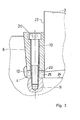
- Figures 3 and 4 show a possibility of wedge locking or wedge detachment.
- the clamping wedge 6 is provided with a radial threaded bore 13 which can receive a locking screw 12.
- the locking screw 12 has a countersunk screw head 20 and is screwed into a blind hole 11 at the bottom of the receiving slot.
- the wedge is supported on its end face 22 with a base plate 25 on the bottom 24 of the receiving slot 4.
- the nominal diameter on the thread of the locking screw 12 is smaller than the nominal diameter of the threaded bore 13.
- a pull-off screw 14 is screwed into the threaded bore 13 until the pull-off screw 14 abuts the bottom of the receiving slot 4.
- the clamping wedge 6 is evidently raised in the direction of arrow B.
- the fangs 3 can be exchanged or reversed without complicated aids. It is not necessary to disassemble the knife roller, since each individual fang can be inserted or removed from the outside.
- the fangs 3 are held on the side by the adjacent sets of cutting knives or by corresponding washers.
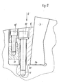
- Figure 5 shows an alternative wedge lock, in which the clamping wedge 6 is secured with a counter wedge 21, which can be locked with the locking screw 12 '.
- the clamping wedge can be removed here with a pull-off screw in the same way as is shown in FIG. 4.
- the clamping wedge 6 is supported on its end face 22 on the bottom 24 of the receiving slot 4.
- the height of the base plate in the exemplary embodiment according to FIG. 3 must be selected such that the clamping wedge can still exert the required clamping force when tightened. In this way, deformation of the clamping wedge can be avoided, since it is practically supported on all sides in the receiving slot 4 or on the end face 23 of the tooth.
- the exemplary embodiment shown can be modified without further ado without departing from the subject matter of the invention. So it is e.g. conceivable that the projecting flank 5 can have a convex curvature in the direction of arrow A. It is also conceivable that the tear tooth 3 can have a different configuration than the one shown.
Landscapes
- Engineering & Computer Science (AREA)
- Food Science & Technology (AREA)
- Crushing And Pulverization Processes (AREA)
- Milling Processes (AREA)
Applications Claiming Priority (2)
| Application Number | Priority Date | Filing Date | Title |
|---|---|---|---|
| CH627880 | 1980-08-20 | ||
| CH6278/80 | 1980-08-20 |
Publications (2)
| Publication Number | Publication Date |
|---|---|
| EP0046452A2 true EP0046452A2 (fr) | 1982-02-24 |
| EP0046452A3 EP0046452A3 (fr) | 1983-03-23 |
Family
ID=4307030
Family Applications (1)
| Application Number | Title | Priority Date | Filing Date |
|---|---|---|---|
| EP81810336A Withdrawn EP0046452A3 (fr) | 1980-08-20 | 1981-08-19 | Appareil déchiqueteur |
Country Status (1)
| Country | Link |
|---|---|
| EP (1) | EP0046452A3 (fr) |
Cited By (8)
| Publication number | Priority date | Publication date | Assignee | Title |
|---|---|---|---|---|
| EP0111038A1 (fr) * | 1982-12-02 | 1984-06-20 | COMPAGNIE CLAYTON Société dite: | Granulateur d'éléments individuels de matériau, notamment de matière plastique |
| DE3545708A1 (de) * | 1985-12-21 | 1987-06-25 | Werner Doppstadt | Umlaufender schlegel zum zerkleinern von materialien |
| US7900861B2 (en) | 2004-03-29 | 2011-03-08 | Progressive Ip Limited | Teeth for grinding apparatus |
| CN102677499A (zh) * | 2012-05-07 | 2012-09-19 | 三明市普诺维机械有限公司 | 高寿命未处理纸浆粉碎辊 |
| CN103191802A (zh) * | 2013-04-26 | 2013-07-10 | 四川皇龙智能破碎技术股份有限公司 | 可快速拆装齿板的破碎机齿辊 |
| EP2295145A3 (fr) * | 2009-09-11 | 2017-02-08 | Herr Willi Schneider | Dispositif de broyage de pierres ou analogues |
| CN110090854A (zh) * | 2019-06-07 | 2019-08-06 | 广州绿邦环境技术有限公司 | 一种用焓变技术处理危废的方法及装置 |
| CN111589549A (zh) * | 2020-06-17 | 2020-08-28 | 郑州洁普智能环保技术有限公司 | 一种厨余垃圾破碎机刀具及厨余垃圾破碎机 |
Family Cites Families (10)
| Publication number | Priority date | Publication date | Assignee | Title |
|---|---|---|---|---|
| US2278274A (en) * | 1939-06-06 | 1942-03-31 | Chain Belt Co | Cutter blade holder for triturators |
| DE930839C (de) * | 1951-10-11 | 1955-07-25 | Westfalia Dinnendahl Groeppel | Rotor fuer Schleudermuehlen |
| US2747803A (en) * | 1952-07-09 | 1956-05-29 | Pettibone Mulliken Corp | Hammer rotor for hammermills |
| DE1015304B (de) * | 1953-10-26 | 1957-09-05 | Hazemag Hartzerkleinerung | Schlagleiste fuer Schleudermuehlenumlaeufer |
| US3151816A (en) * | 1962-06-18 | 1964-10-06 | Pettibone Mulliken Corp | Crusher apparatus and method of manufacture |
| US3146961A (en) * | 1962-08-23 | 1964-09-01 | Fuller Co | Impact hammer |
| GB999020A (en) * | 1963-07-10 | 1965-07-21 | Sheepbridge Equipment Ltd | Improvements in or relating to impact crushers |
| FR2257346A1 (en) * | 1973-10-24 | 1975-08-08 | Baikoff Eugene | Waste disintegrator esp. for old tyres - has elastic axial displacement of cutting discs when encountering very hard material |
| CH584067A5 (fr) * | 1974-03-15 | 1977-01-31 | Andreas E Dr Hazemag Kg | |
| DE2606000A1 (de) * | 1976-02-14 | 1977-08-25 | Hazemag Andreas Kg | Schlagleiste fuer prallmuehlenrotoren |
-
1981
- 1981-08-19 EP EP81810336A patent/EP0046452A3/fr not_active Withdrawn
Cited By (10)
| Publication number | Priority date | Publication date | Assignee | Title |
|---|---|---|---|---|
| EP0111038A1 (fr) * | 1982-12-02 | 1984-06-20 | COMPAGNIE CLAYTON Société dite: | Granulateur d'éléments individuels de matériau, notamment de matière plastique |
| DE3545708A1 (de) * | 1985-12-21 | 1987-06-25 | Werner Doppstadt | Umlaufender schlegel zum zerkleinern von materialien |
| EP0228002A3 (en) * | 1985-12-21 | 1988-07-06 | Werner Doppstadt | Rotating beater for comminuting matter |
| US7900861B2 (en) | 2004-03-29 | 2011-03-08 | Progressive Ip Limited | Teeth for grinding apparatus |
| EP2295145A3 (fr) * | 2009-09-11 | 2017-02-08 | Herr Willi Schneider | Dispositif de broyage de pierres ou analogues |
| CN102677499A (zh) * | 2012-05-07 | 2012-09-19 | 三明市普诺维机械有限公司 | 高寿命未处理纸浆粉碎辊 |
| CN102677499B (zh) * | 2012-05-07 | 2016-03-09 | 三明市普诺维机械有限公司 | 高寿命未处理纸浆粉碎辊 |
| CN103191802A (zh) * | 2013-04-26 | 2013-07-10 | 四川皇龙智能破碎技术股份有限公司 | 可快速拆装齿板的破碎机齿辊 |
| CN110090854A (zh) * | 2019-06-07 | 2019-08-06 | 广州绿邦环境技术有限公司 | 一种用焓变技术处理危废的方法及装置 |
| CN111589549A (zh) * | 2020-06-17 | 2020-08-28 | 郑州洁普智能环保技术有限公司 | 一种厨余垃圾破碎机刀具及厨余垃圾破碎机 |
Also Published As
| Publication number | Publication date |
|---|---|
| EP0046452A3 (fr) | 1983-03-23 |
Similar Documents
| Publication | Publication Date | Title |
|---|---|---|
| EP1789196B1 (fr) | Support de lames destine a des dispositifs hachoirs | |
| EP2620218B1 (fr) | Anneau broyeur d'un cylindre broyeur | |
| EP2012928A1 (fr) | Fleau pour un dispositif de broyage | |
| EP0228002B1 (fr) | Battoir rotatif pour le broyage de matériaux | |
| DE930839C (de) | Rotor fuer Schleudermuehlen | |
| DE2707842C3 (de) | Raspelwerkzeug für eine Schäl- und Raspelvorrichtung zum Abtragen von Reifenlaufflächen | |
| EP0312748B1 (fr) | Cutter pour viande | |
| DE2406204A1 (de) | Befestigung von auswechselbaren schleissplatten an gehaeusewaenden von zerkleinerungsmaschinen | |
| EP0634218A1 (fr) | Rotor pour appareil broyeur | |
| EP2409800B1 (fr) | Outil de coupe rotatif | |
| EP0897751A1 (fr) | Rouleau pour presse à haute pression, notamment pour le broyage en lit de matière de matériau granulaire | |
| AT392740B (de) | Schlagleiste fuer prallbrecher od. dgl. zerkleinerungsmaschinen | |
| DE3438706C2 (de) | Vorrichtung zur Zerkleinerung von Blech und ähnlichem Material | |
| DE202007013269U1 (de) | Schlegel für Zerkleinerungsvorrichtungen | |
| DE2827391C2 (de) | Rotor für eine Zerkleinerungsvorrichtung | |
| CH720075A1 (de) | Statorteil einer Prallmühle und Befestigungsverfahren. | |
| AT398711B (de) | Zylindrischer rotor | |
| DE1221081B (de) | Walze fuer Walzenbrecher | |
| CH672751A5 (fr) | ||
| DE3227862A1 (de) | Zerkleinerungsvorrichtung und verfahren zu deren herstellung | |
| EP0394937A2 (fr) | Couteau rotatif pour un dispositif de coupe de papier | |
| CH720076A2 (de) | Statorteil einer Prallmühle und Befestigungsverfahren. | |
| DE527829C (de) | Tellerfoermige Brechplatte fuer Brechmaschinen | |
| DE7404473U (de) | Befestigung von auswechselbaren schleissplatten an gehaeusewaenden von zerkleinerungsmaschinen | |
| DE2109646C (de) | Ruighammer |
Legal Events
| Date | Code | Title | Description |
|---|---|---|---|
| PUAI | Public reference made under article 153(3) epc to a published international application that has entered the european phase |
Free format text: ORIGINAL CODE: 0009012 |
|
| AK | Designated contracting states |
Designated state(s): AT BE CH DE FR GB IT NL SE |
|
| PUAL | Search report despatched |
Free format text: ORIGINAL CODE: 0009013 |
|
| AK | Designated contracting states |
Designated state(s): AT BE CH DE FR GB IT LI NL SE |
|
| STAA | Information on the status of an ep patent application or granted ep patent |
Free format text: STATUS: THE APPLICATION IS DEEMED TO BE WITHDRAWN |
|
| 18D | Application deemed to be withdrawn |
Effective date: 19840305 |
|
| RIN1 | Information on inventor provided before grant (corrected) |
Inventor name: WYSS, FRANZ JOACHIM |