EP0046569A2 - Procédé et appareil pour mélanger des solides avec des liquides - Google Patents
Procédé et appareil pour mélanger des solides avec des liquides Download PDFInfo
- Publication number
- EP0046569A2 EP0046569A2 EP81106427A EP81106427A EP0046569A2 EP 0046569 A2 EP0046569 A2 EP 0046569A2 EP 81106427 A EP81106427 A EP 81106427A EP 81106427 A EP81106427 A EP 81106427A EP 0046569 A2 EP0046569 A2 EP 0046569A2
- Authority
- EP
- European Patent Office
- Prior art keywords
- mixing
- liquid
- solids
- zone
- mixing container
- Prior art date
- Legal status (The legal status is an assumption and is not a legal conclusion. Google has not performed a legal analysis and makes no representation as to the accuracy of the status listed.)
- Granted
Links
Images


Classifications
-
- B—PERFORMING OPERATIONS; TRANSPORTING
- B27—WORKING OR PRESERVING WOOD OR SIMILAR MATERIAL; NAILING OR STAPLING MACHINES IN GENERAL
- B27N—MANUFACTURE BY DRY PROCESSES OF ARTICLES, WITH OR WITHOUT ORGANIC BINDING AGENTS, MADE FROM PARTICLES OR FIBRES CONSISTING OF WOOD OR OTHER LIGNOCELLULOSIC OR LIKE ORGANIC MATERIAL
- B27N1/00—Pretreatment of moulding material
- B27N1/02—Mixing the material with binding agent
- B27N1/0227—Mixing the material with binding agent using rotating stirrers, e.g. the agent being fed through the shaft of the stirrer
- B27N1/0236—Mixing the material with binding agent using rotating stirrers, e.g. the agent being fed through the shaft of the stirrer with the stirrers rotating about an horizontal axis, e.g. in consecutive casings
- B27N1/0245—Mixing the material with binding agent using rotating stirrers, e.g. the agent being fed through the shaft of the stirrer with the stirrers rotating about an horizontal axis, e.g. in consecutive casings with a single stirrer shaft
-
- B—PERFORMING OPERATIONS; TRANSPORTING
- B01—PHYSICAL OR CHEMICAL PROCESSES OR APPARATUS IN GENERAL
- B01F—MIXING, e.g. DISSOLVING, EMULSIFYING OR DISPERSING
- B01F27/00—Mixers with rotary stirring devices in fixed receptacles; Kneaders
- B01F27/60—Mixers with rotary stirring devices in fixed receptacles; Kneaders with stirrers rotating about a horizontal or inclined axis
- B01F27/62—Mixers with rotary stirring devices in fixed receptacles; Kneaders with stirrers rotating about a horizontal or inclined axis comprising liquid feeding, e.g. spraying means
-
- B—PERFORMING OPERATIONS; TRANSPORTING
- B01—PHYSICAL OR CHEMICAL PROCESSES OR APPARATUS IN GENERAL
- B01F—MIXING, e.g. DISSOLVING, EMULSIFYING OR DISPERSING
- B01F35/00—Accessories for mixers; Auxiliary operations or auxiliary devices; Parts or details of general application
- B01F35/71—Feed mechanisms
- B01F35/717—Feed mechanisms characterised by the means for feeding the components to the mixer
- B01F35/7179—Feed mechanisms characterised by the means for feeding the components to the mixer using sprayers, nozzles or jets
-
- B—PERFORMING OPERATIONS; TRANSPORTING
- B01—PHYSICAL OR CHEMICAL PROCESSES OR APPARATUS IN GENERAL
- B01F—MIXING, e.g. DISSOLVING, EMULSIFYING OR DISPERSING
- B01F35/00—Accessories for mixers; Auxiliary operations or auxiliary devices; Parts or details of general application
- B01F35/90—Heating or cooling systems
- B01F35/92—Heating or cooling systems for heating the outside of the receptacle, e.g. heated jackets or burners
-
- B—PERFORMING OPERATIONS; TRANSPORTING
- B01—PHYSICAL OR CHEMICAL PROCESSES OR APPARATUS IN GENERAL
- B01F—MIXING, e.g. DISSOLVING, EMULSIFYING OR DISPERSING
- B01F35/00—Accessories for mixers; Auxiliary operations or auxiliary devices; Parts or details of general application
- B01F35/90—Heating or cooling systems
- B01F35/95—Heating or cooling systems using heated or cooled stirrers
-
- B—PERFORMING OPERATIONS; TRANSPORTING
- B01—PHYSICAL OR CHEMICAL PROCESSES OR APPARATUS IN GENERAL
- B01F—MIXING, e.g. DISSOLVING, EMULSIFYING OR DISPERSING
- B01F35/00—Accessories for mixers; Auxiliary operations or auxiliary devices; Parts or details of general application
- B01F35/90—Heating or cooling systems
- B01F2035/98—Cooling
-
- B—PERFORMING OPERATIONS; TRANSPORTING
- B01—PHYSICAL OR CHEMICAL PROCESSES OR APPARATUS IN GENERAL
- B01F—MIXING, e.g. DISSOLVING, EMULSIFYING OR DISPERSING
- B01F23/00—Mixing according to the phases to be mixed, e.g. dispersing or emulsifying
- B01F23/50—Mixing liquids with solids
- B01F23/565—Mixing liquids with solids by introducing liquids in solid material, e.g. to obtain slurries
-
- B—PERFORMING OPERATIONS; TRANSPORTING
- B01—PHYSICAL OR CHEMICAL PROCESSES OR APPARATUS IN GENERAL
- B01F—MIXING, e.g. DISSOLVING, EMULSIFYING OR DISPERSING
- B01F27/00—Mixers with rotary stirring devices in fixed receptacles; Kneaders
- B01F27/05—Stirrers
- B01F27/11—Stirrers characterised by the configuration of the stirrers
- B01F27/112—Stirrers characterised by the configuration of the stirrers with arms, paddles, vanes or blades
Definitions
- the invention relates to a method for mixing solids with liquids, in particular for gluing wood chips according to the preamble of claim 1 and a device for carrying out this method according to the preamble of claim 6.
- Such methods and devices are known from DE-PS 2o 57 594 and DE-AS 21 13 96o (corresponding to US Pat. No. 3,734,471).
- These wood chip glue mixers have revolutionized chip glueing because they have extremely fine distribution of the glue on the surface of the chips in the smallest space with the highest intensity, which saves a lot of glue and also saves equipment costs compared to the previously usual, large-volume ones Thrust or spin and vortex mixers was achieved.
- the mechanism of action in these so-called ring mixers is such that the material to be mixed is accelerated by a mixing mechanism which is driven far more critically than it is in the form of a relatively thin ring of material to be mixed moved helically on the inner wall of the mixing container.
- the glue is introduced directly into this mix ring, specifically in the embodiments according to the publications mentioned by the hollow mixer shaft and liquid feed tubes protruding radially therefrom and immersed in the mix ring or in another embodiment according to DE - PS 21 34 3o5 by liquid addition pipes, which are fixed in the container wall and are guided through this into the interior of the mixing container and end with their outlet openings in the mixture ring.
- the invention is therefore based on the object of a method of the generic type and a device of ; Generic type to create, whereby damage to the solids is largely avoided and a better liquid distribution is achieved.
- the essence of the invention lies in that the acceleration of the chips extends over a relatively long period of time in comparison with the known ring mixers, that is to say it takes place much more slowly. This considerably reduces the acceleration forces, ie the forces that lead to possible chip damage. So there is a continuous, temporally stretched acceleration from a shear mixing movement through a centrifugal and vortex mixing movement to a ring mixing movement.
- the glue is added partly in the shear mixing movement of the chips and then in the centrifugal and whirling mixing movement of the chips, ie even during the glue addition no mechanical forces need to be applied by impurities or the like in order to distribute the glue onto the chips.
- the advantageous, high-intensity glue distribution takes place on the surface of the chips in a mix ring. Due to the conical expansion of the mixing container in the acceleration zone, the necessarily increased volume is continuously created, in which the chips can distribute themselves from the packing, which is comparatively dense during the thrust mixing movement, into a loosened volume during the spinning and mixing movement.
- a sufficiently large radius of the mixing container is then again available in the mixing zone, which is necessary so that the tangential accelerations required for the formation of the mixing material ring are generated.
- the nature of the glue addition in the acceleration zone makes it possible again to use the glue addition known per se through pressure nozzles, which leads to the considerable advantage that the glue can be used with a lower water content than has been customary hitherto. So far, a ratio of glue dry weight to water of 1: 1 has been used. This reduction in the water content leads to the water content of the wood chips can be correspondingly higher; The energy-consuming drying of the wood chips can therefore be ended a little earlier than is currently possible.
- Corresponding advantages apply in general when mixing pourable or free-flowing solids with liquids, which can be, for example, concentrate on the one hand and molasses on the other hand.
- the measures according to claim 2 enable a particularly good transition from the thrust movement to the centrifugal and whirling movement to the ring movement.
- the wood chips are whirled extremely strongly by practically the entire cross section of the mixing container at this point by the air serving as carrier gas for the glue in the area of the glue addition, so that here a very uniform distribution of the glue on the chip surfaces takes place .
- energy ie. H. the energy required to mix a predetermined weight of wood chips with a predetermined weight of glue is significantly reduced.
- the measures according to claims 4 and 5 ensure that a large-area nebulization of the glue is achieved, the individual microscopic secondary droplets being applied at extremely high speeds from the outside to the swirling mix and therefore penetrating deeply into it, since it is still not as close as in the ring. Since there are to a greater extent coarse chips than fine chips or dust in the vicinity of the mixing container wall, these are glued to an increased extent, which is desirable.
- Claims 6 to 14 represent the constructive possibilities for realizing the method measures according to claims 1 to 5 in a particularly advantageous manner.
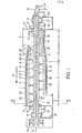
- the mixers shown in the drawing differ only in the area on the right in the drawing the mixer shown in FIG. 2 is shown closed in its area corresponding to FIG. 1.
- the mixers each have a mixing container 1, which consists of an inner trough 2 forming the inner wall thereof and a cooling jacket 3 surrounding the inner trough and forming the outer wall.
- the mixing container 1 is closed at its ends by end walls 4, 5.
- a mixed material feed funnel 6 is provided which opens tangentially from above into the interior 7 of the mixing container 1 enclosed by the inner trough 2 and the end walls 4 and 5.
- At the other end - on the left in FIGS. 1 and 2 - there is also a tangentially discharging mix outlet funnel 8.
- the mixing container 1 is divided in half in the horizontal plane, the upper half 9 and the lower half 1o of the mixing container 1 being held together on one long side by hinge joints 11 and on the opposite long side by toggle locks 12 so that they can be swung open.
- a mixer shaft 13 is arranged coaxially, which is mounted in bearings 14, 15 and can be driven by an electric motor, not shown, via a V-belt pulley 16 which is non-rotatably mounted on the mixer shaft 13.
- Balancing disks 17, 18 are also mounted on the mixer shaft 13 outside the mixing container 1, but in the vicinity of the end walls 4, 5.
- bushings mounted 19, are screwed into the hollow formed M isch- tools 2o.
- the mixer shaft 13 is arranged with a rotating cooling water supply pipe 21, each of which branches into each hollow mixing tool 2o, a cooling water pipe 22, so that the cooling water through the cooling water supply pipe 21, the branching cooling water pipes 22, flows through the interior of each mixing tool 2o into the annular space 23 located between the cooling water supply pipe 21 and the mixer shaft 13.
- the cooling water passes through a cooling water connection 24, which is provided on the right in FIGS. 1 and 2, into the mixer shaft 13, the cooling water inflow in direction a into the cooling water supply pipe 21 and the cooling water outflow in direction b from the annular space 23.
- the bearings 14, 15 are supported on pedestals 25, 26.
- the area of the mixing container 1, over which the mixed material feed funnel 6 extends in the longitudinal direction of the mixing container 1, is cylindrical and forms a feed zone A for the mixed material, usually therefore wood chips.
- feed tools are mounted on the mixer shaft 13, which in the embodiment according to FIG. 1 are feed tools 27 designed in the manner of blades and in the embodiment according to FIG. 2 a feed tool 28 designed like a screw.
- the feed tools 27 or 28 are used so that through the mixed material inlet funnel 6 in this cylindrical Ab-. Section 29 of the mixing container 1 falling mix is conveyed in a primarily aially directed pushing movement into the next subsequent, conical section of the mixing container.
- This section 3o which widens conically in the direction of flow 31 of the mixing container 1, that is to say in the shape of a truncated cone, forms an acceleration zone B for the mixed material.
- This conical section 3o is followed by a likewise cylindrical section 32 of the mixing container 1, which has a mixing zone C which extends as far as the mixing material outlet funnel 8 and an ejection zone D which extends over the axial length of the mixing material outlet funnel 8 forms.
- the conical section 3o widens from the radius r 29 to the radius r 32 of the cylindrical section 32.
- the ratio of the radii r 29 to r 32 is o.6 to o.8, preferably approximately o.75.
- the opening angle ⁇ of the conical portion 3o is about 8 to 15 °, preferably about 1 0 °.
- the axial length ratio of acceleration. Inclination zone B to mixing zone C is approximately 1: 2.
- the mixing tools are designed with a considerably smaller radial extension than in the cylindrical section 32.
- the acceleration zone B is present Mixing tools with the reference numeral 20 ', the radial length of these mixing tools 2o' from the beginning of the acceleration zone B, i.e. from the end of the feed zone A, to the end of the acceleration zone B, i.e. to the beginning of the mixing zone C, increasing continuously, as from the drawing shows.
- liquid addition pipes 33 (FIG. 1) or 34 (FIG. 2) open for the addition of glue to wood chips.
- the liquid addition tubes 33 end approximately flush with the inner wall of the conical section 3o of the mixing container 1 formed by the inner trough 2 27 38 971 (U.S. Patent 4,183,676).
- the liquid can also be fed to them under pressure.
- atomizing nozzles 35 are attached to the inner ends of the liquid addition tubes 33, as is known, for example, from DE-PS 12 13 385 (corresponding to US-PS 3 163 4o3).
- the liquid addition tubes 33 are substantially the same as that of the input zone A seen from the front section of the acceleration zone B.
- the liquid addition pipes 34 protrude into the interior 7 of the mixing container 1 to different degrees, the first liquid addition pipe 34 ′, seen again from the feed zone A in the direction of passage 31, extending radially furthest from the inner wall into the interior while the downstream liquid addition pipes 34 ", 34" 'and 34 “” each extend less deeply from the wall into the interior 7, so that the last liquid addition pipe 34 "" is again flush with the inner wall.
- the supply of liquid can take place in the same way without pressure or under pressure, in each case the liquid emerging at the radially inner end of the respective liquid addition pipe 34.
- the liquid addition pipes 33 and 34 lie in the vertical axis plane of the mixing container 1.
- the liquid outlet openings 36 are therefore arranged on a line which forms an angle ⁇ with the longitudinal axis 37 of the mixing container 1, which angle is in any case significantly larger than ⁇ .
- ⁇ is about 20 to 25 °.
- a throttle valve 38 is arranged in the usual manner on the mixing material discharge funnel -8, which is articulated on its upper, axially parallel edge by means of swivel joints 39 on the mixing container 1 and by the pressure of the mixing material from the closed position shown in FIG. 3 downwards and to the side corresponding to that Swivel direction arrow 4o can be pivoted so that the mixture outlet opening is opened more or less, so that in turn the mixing tools 2o moving in the direction of rotation 41 eject the material to be mixed through the then more or less opened material outlet opening into the material outlet funnel 8.
- a motor-adjustable counterweight 42 is attached, as is known in detail from patent application P 29-23 5o2 (US Ser. No. 154 o98). This motor-adjustable counterweight serves to superimpose the possibility that the throttle valve opens in accordance with the pressure of the material to be mixed in the mixing container 1, the further possibility of changing the closing pressure present in each open position of the throttle valve 38 by adjusting the counterweight 42.
- the mixer shaft 13 is driven at high speed, so that there is a far supercritical speed, at least in the mixing zone C.
- the critical speed is defined in that when it reaches the radially outer ends of the mixing tools 2o, an acceleration corresponding to the acceleration due to gravity acts. So that corresponding acceleration forces can be exerted, the mixing tools 2o and 2o 'end in the vicinity of the inner wall of the mixing container 1. This applies in particular to the mixing tools 2o arranged in the mixing zone C, since here the mixture ring 43 is relatively thin and the mixing tools 2o in have to protrude this mix ring 43 in order to continuously exert acceleration forces on the wood chips forming the mix ring 43.
- pressurized gas can of course be used as an additional atomization aid.
- liquid addition nozzles 44 intended for adding glue to wood chips, which are flush with the inside of the inner trough 2 of the mixing container 1, ie do not protrude into the interior 7 of the mixing container 1.
- these liquid addition nozzles 44 open predominantly tangentially into the interior 7.
- These nozzles are so-called two-component nozzles, through which liquid glue, which is supplied through a glue supply line 45, and compressed air, which is supplied through a compressed air line 46, are sprayed into the interior 7 in a finely divided manner.
- the centrifugal and whirling movement of the chips is significantly supported by the air sprayed in through the liquid addition nozzles 44, which not only serves as a carrier for the glue, that is to say for the glue division, but also substantially loosens the chips.
- the compressed air is supplied to the liquid addition nozzles 44 at a pressure in the range from 2 to 6 bar, preferably at a pressure from 2.5 to 4 bar.
- the liquid addition nozzles 44 are supplied with compressed air in a ratio of 2 to 5 standard m 3 / m 3 chips, and preferably 2.5 to 3.5 standard m 3 air per m 3 chips .
- the conical section 30 ′ widens from the radius r 29 to the radius r 32 of the cylindrical section 32 ′.
- the ratio of the radii r 29 to r 32, is o 55 to o, 7, preferably about o, o 6 to, 65th
- the opening angle ⁇ 'of the conical portion 3o is about 12 to 2 0 °, preferably about 18 °.
- the axial length ratio of acceleration zone B to mixing zone C is approximately 1: 2.
- the mixing tools are also designed there with a considerably smaller radial extent than in the cylindrical section 31.
- the mixing tools in this acceleration zone B ' are provided with the reference number 2 0 ", the radial length of these mixing tools 2 0 " from the beginning of the acceleration zone B', that is to say from the end of the feed zone A ', to the end of the acceleration zone B', up to the beginning of the mixing zone C ', increases approximately continuously, as can be seen from FIG. 5.
- the mixing tools are formed as blade-like for the production of tangential movements of the mix and therefore the reference numeral 2 0' ', respectively.
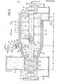
- a glue addition device 47 which works according to the centrifugal principle. It has two centrifugal disks connected to one another in a rotationally fixed manner, namely an inner centrifugal plate 48 and an outer centrifugal plate 49, which between them define a gap 51 which is largely radial to the central longitudinal axis 50 of the glue addition device 47.
- the outer that is, the centrifugal plate 49 facing the inner wall of the mixing container 1 merges into a tubular section 52 in which a likewise tubular centering section 53 is fixed by means of some radial webs 54 is arranged.
- the inner centrifugal disc 48 has a centering collar 55, by means of which it is held radially and axially in the tubular centering section 53.
- the width c of the largely annular disk-shaped gap 51 can be changed by a corresponding length of the tubular centering section 53 or by interposing washers at the separation point between the centering collar 55 and the centering section 53.
- a conventional electric motor 56 is used to drive the centrifugal plate 48, 49, which is screwed to a short support frame 57, which in turn is screwed onto a pipe socket 58 penetrating the inner trough 2 'and the cooling jacket 3' of the mixing container 1 ', the latter of which Inner diameter is slightly larger than the outer diameter of the tubular section 52.
- This support frame 57 consists of a few webs 59 which extend parallel to the axis 50 and each end-mounted ring flanges 6 0 , 61, which are fitted with a corresponding flange 62 of the pipe socket 58 or the connecting flange 63 of the electric motor 56 are detachably screwed by means of screws 64.
- the centrifugal discs 48, 49 are screwed to the shaft journal 66 of the motor 56 in a rotationally fixed manner by means of a threaded screw passing through the centering collar 55 coaxially to the axis 50, whereby a filler piece 67 is provided which is axially supported on the one hand against the shaft journal 66, and in turn in the Centering section 53 engages, which is supported axially via a collar 68 against the filler 67, so that when the threaded screw 65 is tightened, the inner centrifugal disc 48 with its centering segment 53 of the outer centrifugal disc 49 and thus the latter are firmly clamped to the shaft journal 66.
- centrifugal plate is axially fixed with simultaneous determination of the width c of the gap 51 and rotatably connected to the shaft journal 66.
- annular disk 69 is fastened, to which a cylindrical ring channel 7o, which is closed toward it, is screwed, which into the glue space 71 between the tubular section 52 and the centering section 53 flows openly.
- a threaded connector 72 opens into the side of the annular channel 7o, to which a glue supply line (not shown) can be connected.
- the gap does not pass 51 exactly radially, but in the form of a truncated cone with a very large opening angle or very small foot angle ⁇ of approximately 5 to 10 °, which an opening angle of 17o corresponding to 16 0 0.
- the angle / 3 can for example be chosen so that it is equal to ⁇ '/ 2; if the glue addition device 47 is arranged at the transition from the conical section 30 'to the cylindrical section 32'. In this case - based on the longitudinal section of the mixer shown in Fig. 5 - the glue addition device 47 is arranged so that its longitudinal axis 5o is inclined at an angle of ⁇ '/ 2.
- the glue is added to zone B 'in such a way that glue is metered into a ring channel 7o from a pump, not shown, via a glue supply line, also not shown, from where it runs down into the glue space 71, as indicated by flow arrows 73 .
- the glue is accelerated radially strongly and expelled through the gap 51 and leaves the latter in the form of a fine mist at a very high tangential speed.
- the rotational speed of the centrifugal plate is usually 2800 rpm, which is the case with a diameter of the centrifugal plate 48, 49 of 140 mm and a peripheral speed of the centrifugal plate Exit of the gap 51 corresponds to slightly more than 20 m / sec.
- the glue is thus distributed extremely finely and introduced into the material, in particular the chips, from the outside at a very high speed.
- part of the glue is deposited on the inner wall of the inner trough 2'. Since the inner wall has a relatively low temperature due to the good cooling of the mixer, Kodensat water precipitates here, which leads to a dilution of the deposited glue, so that it can be particularly easily absorbed by passing wood chips. Since there are coarse chips rather than fine chips or dust in the wall area, these coarse chips are thereby glued relatively more strongly, which is desirable.
- a mixture ring 74 is formed on the inner wall of the mixing container 1', in which the wood chips and the glue are thoroughly mixed.
- the mixing tools 2 0 ′′ or 20 ′ run past the inner centrifugal plate 48. If the mixing material ring 74 were also already formed in this area of the mixing container 1 in its initial stage, this would result he brush past the inside of the inner spinner 48. Due to the fact that the outer spinner 49 is also driven at high speed, no chips can get into the space, which is only a few millimeters wide, between the inner wall of the inner trough 2 'and the spinner 49. If a such a ring is already partially formed, the glue mist is applied from the outside to this mixture ring.
- the glue addition device 47 can be supplied with the glue without pressure, which enables particularly precise metering in a known manner.
- centrifugal plates 48, 49 are tapered in their outer circumference towards the exit of the gap, so that the centrifugal plates 48, 49 as a whole do not have a cylindrical ring edge on which mixed material, that is to say chips, could be stowed.
- the chips can therefore run smoothly past the inside of the inner spin plate 48.
- a web-like fan blade 75 can be arranged on the outer centrifugal plate 49, which improves the cleaning effect of the rotating centrifugal plate 49 towards the inner wall of the inner trough 2 '.
Landscapes
- Chemical & Material Sciences (AREA)
- Chemical Kinetics & Catalysis (AREA)
- Engineering & Computer Science (AREA)
- Mechanical Engineering (AREA)
- Life Sciences & Earth Sciences (AREA)
- Manufacturing & Machinery (AREA)
- Wood Science & Technology (AREA)
- Forests & Forestry (AREA)
- Dispersion Chemistry (AREA)
- Mixers Of The Rotary Stirring Type (AREA)
- Dry Formation Of Fiberboard And The Like (AREA)
- Accessories For Mixers (AREA)
Applications Claiming Priority (6)
| Application Number | Priority Date | Filing Date | Title |
|---|---|---|---|
| DE3032039A DE3032039C2 (de) | 1980-08-26 | 1980-08-26 | Verfahren und Vorrichtung zum Beleimen von Holzspänen |
| DE3032039 | 1980-08-26 | ||
| DE19803036346 DE3036346A1 (de) | 1980-08-26 | 1980-09-26 | Verfahren und vorrichtung zum beleimen von holzspaenen |
| DE3036346 | 1980-09-26 | ||
| DE19813105549 DE3105549A1 (de) | 1981-02-16 | 1981-02-16 | Verfahren und vorrichtung zum beleimen von holzspaenen |
| DE3105549 | 1981-02-16 |
Publications (3)
| Publication Number | Publication Date |
|---|---|
| EP0046569A2 true EP0046569A2 (fr) | 1982-03-03 |
| EP0046569A3 EP0046569A3 (en) | 1984-05-23 |
| EP0046569B1 EP0046569B1 (fr) | 1986-07-16 |
Family
ID=27188841
Family Applications (1)
| Application Number | Title | Priority Date | Filing Date |
|---|---|---|---|
| EP81106427A Expired EP0046569B1 (fr) | 1980-08-26 | 1981-08-19 | Procédé et appareil pour mélanger des solides avec des liquides |
Country Status (5)
| Country | Link |
|---|---|
| US (1) | US4390285A (fr) |
| EP (1) | EP0046569B1 (fr) |
| JP (1) | JPS5771629A (fr) |
| DE (1) | DE3174930D1 (fr) |
| FI (1) | FI812580A7 (fr) |
Cited By (7)
| Publication number | Priority date | Publication date | Assignee | Title |
|---|---|---|---|---|
| EP0154901A3 (fr) * | 1984-02-28 | 1988-04-06 | Zaklady Produkcji Urzadzen Mechanicznych im. Janka Krasickiego "ELWO" | Mélangeur |
| WO2000061273A3 (fr) * | 1999-04-14 | 2001-04-19 | Merkle Eng Inc | Chargeur de materiau humidifie dans un cylindre a vis sans fin |
| US6292457B1 (en) | 1999-03-31 | 2001-09-18 | Eastman Kodak Company | Recordable optical media with a silver-gold reflective layer |
| EP1604732A4 (fr) * | 2003-02-27 | 2007-12-05 | M & F Technology Co Ltd | Dispositif de melange et de pulverisation, procede de fusion pour le melange, et procede de moulage de materiau en cellulose impregne de liant |
| EP2563558A1 (fr) | 2010-04-30 | 2013-03-06 | Imal S.R.L. | Appareil pour injecter des composants chimiques dans un flux de bois en vrac |
| CN106985255A (zh) * | 2017-05-15 | 2017-07-28 | 中南林业科技大学 | 农林加工剩余物基无机复合材步级施胶装置及施胶方法 |
| WO2017216140A3 (fr) * | 2016-06-14 | 2018-03-15 | Interbran Systems Ag | Mélangeur |
Families Citing this family (20)
| Publication number | Priority date | Publication date | Assignee | Title |
|---|---|---|---|---|
| DE3304129A1 (de) * | 1983-02-08 | 1984-08-09 | Draiswerke Gmbh, 6800 Mannheim | Verfahren und mischer zum kontinuierlichen beleimen von aus holz-spaenen, -fasern od. dgl. bestehendem mischgut |
| US5580170A (en) * | 1995-10-06 | 1996-12-03 | Ferro-Tech, Inc. | Mixing and conditioning machine |
| US6517232B1 (en) | 1996-05-20 | 2003-02-11 | Becker-Underwood, Inc. | Mixing systems |
| US6162496A (en) * | 1996-05-20 | 2000-12-19 | Blue; David | Method of mixing |
| US5626421A (en) * | 1996-05-28 | 1997-05-06 | Campbell; Craig C. | Blender construction |
| US5881796A (en) * | 1996-10-04 | 1999-03-16 | Semi-Solid Technologies Inc. | Apparatus and method for integrated semi-solid material production and casting |
| US5887640A (en) | 1996-10-04 | 1999-03-30 | Semi-Solid Technologies Inc. | Apparatus and method for semi-solid material production |
| JP3209941B2 (ja) * | 1997-04-28 | 2001-09-17 | 花王株式会社 | 混合方法および混合装置 |
| CN1115215C (zh) | 1998-07-24 | 2003-07-23 | 吉布斯压铸铝股份有限公司 | 半固态铸造的设备和方法 |
| US6551401B1 (en) | 2000-10-19 | 2003-04-22 | Becker-Underwood, Inc. | Machine for coloring landscaping material |
| AT410298B (de) * | 2001-06-11 | 2003-03-25 | Bacher Helmut | Vorrichtung zur befüllung einer in einem gehäuse gelagerten schnecke und verfahren zum betrieb einer solchen vorrichtung |
| DE10347052A1 (de) | 2003-10-07 | 2005-05-04 | Schenkmann Piel Engineering Gm | Verfahren zur Herstellung von Faserplatten aus Holzfasern |
| ITMO20040127A1 (it) | 2004-05-25 | 2004-08-25 | Imal Srl | Procedimento di incollaggio di frammenti o trucioli di legno per osb e apparato di incollaggio relativo. |
| JP5085929B2 (ja) * | 2006-12-27 | 2012-11-28 | 株式会社ツカサ | 粉粒体混合装置 |
| DE102009057916B4 (de) * | 2009-05-15 | 2015-04-02 | Siempelkamp Maschinen- Und Anlagenbau Gmbh | Verfahren und Vorrichtung zum kontinuierlichen Mischen von Fasern mit einem Bindemittel |
| US9340741B2 (en) * | 2009-09-09 | 2016-05-17 | Gas Technology Institute | Biomass torrefaction mill |
| US7883263B1 (en) | 2010-08-30 | 2011-02-08 | Wenger Manufacturing, Inc. | Preconditioner for extrusion systems |
| US9713893B2 (en) * | 2013-07-09 | 2017-07-25 | Wenger Manufacturing, Inc. | Method of preconditioning comestible materials using steam/water static mixer |
| PL404773A1 (pl) * | 2013-07-18 | 2015-01-19 | Ajh047 Spółka Z Ograniczoną Odpowiedzialnością | Sposób nanoszenia mikrocząstek metalu na materiał polimerowy, urządzenie do realizacji sposobu, materiał polimerowy z mikrocząsteczkami metalu oraz zastosowanie materiału polimerowego |
| CN107921155A (zh) * | 2015-08-26 | 2018-04-17 | 株式会社佐竹 | 过热蒸汽灭菌装置 |
Family Cites Families (6)
| Publication number | Priority date | Publication date | Assignee | Title |
|---|---|---|---|---|
| US3162428A (en) * | 1961-07-15 | 1964-12-22 | Loedige Wilhelm | Process for mixing and wetting solid materials |
| US3355106A (en) * | 1964-04-30 | 1967-11-28 | Stratford Eng Corp | Mixing atomizing rotor |
| US3522934A (en) * | 1968-08-08 | 1970-08-04 | Ulrich Walter | Method and apparatus for producing a homogeneous mixture of granular and viscous substances |
| US4015829A (en) * | 1973-09-01 | 1977-04-05 | Wilhelm Lodige | Apparatus for applying glue to fiber material |
| DE2344231C2 (de) * | 1973-09-01 | 1984-09-13 | Lödige, Fritz | Mischwerkzeuge bei Vorrichtungen zum Beleimen von Fasern und Verfahren hierzu |
| DE2738971A1 (de) * | 1977-08-30 | 1979-03-22 | Draiswerke Gmbh | Verfahren und vorrichtung zum beleimen von holzspaenen |
-
1981
- 1981-08-12 US US06/292,213 patent/US4390285A/en not_active Expired - Fee Related
- 1981-08-19 EP EP81106427A patent/EP0046569B1/fr not_active Expired
- 1981-08-19 DE DE8181106427T patent/DE3174930D1/de not_active Expired
- 1981-08-21 FI FI812580A patent/FI812580A7/fi not_active Application Discontinuation
- 1981-08-26 JP JP56133922A patent/JPS5771629A/ja active Pending
Cited By (11)
| Publication number | Priority date | Publication date | Assignee | Title |
|---|---|---|---|---|
| EP0154901A3 (fr) * | 1984-02-28 | 1988-04-06 | Zaklady Produkcji Urzadzen Mechanicznych im. Janka Krasickiego "ELWO" | Mélangeur |
| TR22876A (tr) * | 1984-02-28 | 1988-09-23 | Zaklady Prod Urzadzen Mechan | Ince taneli ve tozlu kati cisimlerin su ile karistirilmasi icin akish mikser |
| US6292457B1 (en) | 1999-03-31 | 2001-09-18 | Eastman Kodak Company | Recordable optical media with a silver-gold reflective layer |
| WO2000061273A3 (fr) * | 1999-04-14 | 2001-04-19 | Merkle Eng Inc | Chargeur de materiau humidifie dans un cylindre a vis sans fin |
| US6349570B1 (en) | 1999-04-14 | 2002-02-26 | Merkle Engineers, Inc. | In-barrel wetting screw charger |
| EP1604732A4 (fr) * | 2003-02-27 | 2007-12-05 | M & F Technology Co Ltd | Dispositif de melange et de pulverisation, procede de fusion pour le melange, et procede de moulage de materiau en cellulose impregne de liant |
| US7896638B2 (en) | 2003-02-27 | 2011-03-01 | M & F Technology Co., Ltd. | Mixing and pulverizing device, melting method for mixing, and method of molding cellulose material impregnated with binder |
| EP2563558A1 (fr) | 2010-04-30 | 2013-03-06 | Imal S.R.L. | Appareil pour injecter des composants chimiques dans un flux de bois en vrac |
| EP2563558B1 (fr) | 2010-04-30 | 2018-06-20 | Imal S.R.L. | Appareil pour injecter des composants chimiques dans un flux de bois en vrac |
| WO2017216140A3 (fr) * | 2016-06-14 | 2018-03-15 | Interbran Systems Ag | Mélangeur |
| CN106985255A (zh) * | 2017-05-15 | 2017-07-28 | 中南林业科技大学 | 农林加工剩余物基无机复合材步级施胶装置及施胶方法 |
Also Published As
| Publication number | Publication date |
|---|---|
| JPS5771629A (en) | 1982-05-04 |
| EP0046569A3 (en) | 1984-05-23 |
| EP0046569B1 (fr) | 1986-07-16 |
| FI812580L (fi) | 1982-02-27 |
| FI812580A7 (fi) | 1982-02-27 |
| US4390285A (en) | 1983-06-28 |
| DE3174930D1 (en) | 1986-08-21 |
Similar Documents
| Publication | Publication Date | Title |
|---|---|---|
| EP0046569B1 (fr) | Procédé et appareil pour mélanger des solides avec des liquides | |
| DE69106970T2 (de) | Sprühtrocknung. | |
| DE3304129A1 (de) | Verfahren und mischer zum kontinuierlichen beleimen von aus holz-spaenen, -fasern od. dgl. bestehendem mischgut | |
| DE1213385B (de) | Mischmaschine | |
| EP0739235A1 (fr) | Dispositif de production de pastilles | |
| DE1457270B2 (de) | Fluessigkeitsmischer | |
| EP0638365A2 (fr) | Procédé et dispositif pour séparer des matières solides à grains fins en deux fractions granulométriques | |
| DE4115047C1 (en) | Continuous glue applicator to wood chips - has cooled mixt. application tools, and glue make-up mechanism | |
| DE2438818A1 (de) | Vorrichtung zum kontinuierlichen beleimen von fasern | |
| DD232844A5 (de) | Verfahren und vorrichtung zum trennschleudern von feinkornmineralgemischen | |
| DE3313380C2 (de) | Verfahren und Vorrichtung zum kontinuierlichen Mischen von Feststoffteilchen mit zumindest einer Flüssigkeit | |
| DE3016031C2 (de) | Verfahren zum Beleimen von Spänen, Fasern o.dgl. lignozellulosehaltigen Teilchen und Beleimmaschine zur Durchführung des Verfahrens | |
| DE4332977A1 (de) | Reib-Mühle und deren Verwendung | |
| DE1557124B2 (de) | Vorrichtung zum benetzen von schuettguetern | |
| DE3032039C2 (de) | Verfahren und Vorrichtung zum Beleimen von Holzspänen | |
| DE3117682C2 (de) | Verfahren und Vorrichtung zum kontinuierlichen Beleimen von Holzspänen und anderen lignozellulosehaltigen Partikeln | |
| DE3105549A1 (de) | Verfahren und vorrichtung zum beleimen von holzspaenen | |
| DE2304262A1 (de) | Vorrichtung zum beleimen von spaenen, fasern oder aehnlichem mischgut aus holz oder dgl. fuer die spanplattenherstellung | |
| DE2534649A1 (de) | Vorrichtung zum kontinuierlichen mischen von feststoffen mit fluessigkeiten | |
| DE2738971A1 (de) | Verfahren und vorrichtung zum beleimen von holzspaenen | |
| DE441194C (de) | Vorrichtung zum Zerstaeuben von Fluessigkeiten | |
| DE2930312A1 (de) | Siebzentrifuge | |
| DE2057594C3 (de) | Vorrichtung zum kontinuierlichen Mischen von Feststoffen mit Flüssigkeiten | |
| DE1203734B (de) | Anlage zur Extraktion von loeslichen Stoffen aus festen pflanzlichen, tierischen oder anorganischen Stoffen im Gegenstrom | |
| CH646635A5 (en) | Process for gluing chips for the production of chipboards and device for this purpose |
Legal Events
| Date | Code | Title | Description |
|---|---|---|---|
| PUAI | Public reference made under article 153(3) epc to a published international application that has entered the european phase |
Free format text: ORIGINAL CODE: 0009012 |
|
| AK | Designated contracting states |
Designated state(s): BE CH DE FR GB IT |
|
| 17P | Request for examination filed |
Effective date: 19820320 |
|
| PUAL | Search report despatched |
Free format text: ORIGINAL CODE: 0009013 |
|
| AK | Designated contracting states |
Designated state(s): BE CH DE FR GB IT LI |
|
| GRAA | (expected) grant |
Free format text: ORIGINAL CODE: 0009210 |
|
| AK | Designated contracting states |
Kind code of ref document: B1 Designated state(s): BE CH DE FR GB IT LI |
|
| PG25 | Lapsed in a contracting state [announced via postgrant information from national office to epo] |
Ref country code: IT Free format text: LAPSE BECAUSE OF FAILURE TO SUBMIT A TRANSLATION OF THE DESCRIPTION OR TO PAY THE FEE WITHIN THE PRESCRIBED TIME-LIMIT;WARNING: LAPSES OF ITALIAN PATENTS WITH EFFECTIVE DATE BEFORE 2007 MAY HAVE OCCURRED AT ANY TIME BEFORE 2007. THE CORRECT EFFECTIVE DATE MAY BE DIFFERENT FROM THE ONE RECORDED. Effective date: 19860716 Ref country code: FR Free format text: THE PATENT HAS BEEN ANNULLED BY A DECISION OF A NATIONAL AUTHORITY Effective date: 19860716 Ref country code: BE Effective date: 19860716 |
|
| REF | Corresponds to: |
Ref document number: 3174930 Country of ref document: DE Date of ref document: 19860821 |
|
| PG25 | Lapsed in a contracting state [announced via postgrant information from national office to epo] |
Ref country code: LI Effective date: 19860831 Ref country code: CH Effective date: 19860831 |
|
| EN | Fr: translation not filed | ||
| REG | Reference to a national code |
Ref country code: CH Ref legal event code: PL |
|
| PG25 | Lapsed in a contracting state [announced via postgrant information from national office to epo] |
Ref country code: DE Effective date: 19870501 |
|
| PLBE | No opposition filed within time limit |
Free format text: ORIGINAL CODE: 0009261 |
|
| STAA | Information on the status of an ep patent application or granted ep patent |
Free format text: STATUS: NO OPPOSITION FILED WITHIN TIME LIMIT |
|
| GBPC | Gb: european patent ceased through non-payment of renewal fee | ||
| 26N | No opposition filed | ||
| PG25 | Lapsed in a contracting state [announced via postgrant information from national office to epo] |
Ref country code: GB Free format text: LAPSE BECAUSE OF NON-PAYMENT OF DUE FEES Effective date: 19881118 |