EP0046692A2 - Dispositif de pesage pour un chariot élévateur à fourche - Google Patents
Dispositif de pesage pour un chariot élévateur à fourche Download PDFInfo
- Publication number
- EP0046692A2 EP0046692A2 EP81303881A EP81303881A EP0046692A2 EP 0046692 A2 EP0046692 A2 EP 0046692A2 EP 81303881 A EP81303881 A EP 81303881A EP 81303881 A EP81303881 A EP 81303881A EP 0046692 A2 EP0046692 A2 EP 0046692A2
- Authority
- EP
- European Patent Office
- Prior art keywords
- fork
- fork lift
- deformable member
- lift truck
- weight
- Prior art date
- Legal status (The legal status is an assumption and is not a legal conclusion. Google has not performed a legal analysis and makes no representation as to the accuracy of the status listed.)
- Granted
Links
Images



Classifications
-
- G—PHYSICS
- G01—MEASURING; TESTING
- G01G—WEIGHING
- G01G3/00—Weighing apparatus characterised by the use of elastically-deformable members, e.g. spring balances
- G01G3/12—Weighing apparatus characterised by the use of elastically-deformable members, e.g. spring balances wherein the weighing element is in the form of a solid body stressed by pressure or tension during weighing
- G01G3/14—Weighing apparatus characterised by the use of elastically-deformable members, e.g. spring balances wherein the weighing element is in the form of a solid body stressed by pressure or tension during weighing measuring variations of electrical resistance
- G01G3/1402—Special supports with preselected places to mount the resistance strain gauges; Mounting of supports
- G01G3/1404—Special supports with preselected places to mount the resistance strain gauges; Mounting of supports combined with means to connect the strain gauges on electrical bridges
-
- G—PHYSICS
- G01—MEASURING; TESTING
- G01G—WEIGHING
- G01G19/00—Weighing apparatus or methods adapted for special purposes not provided for in the preceding groups
- G01G19/08—Weighing apparatus or methods adapted for special purposes not provided for in the preceding groups for incorporation in vehicles
- G01G19/083—Weighing apparatus or methods adapted for special purposes not provided for in the preceding groups for incorporation in vehicles lift truck scale
Definitions
- This invention relates generally to electrical weighing systems and pertains particularly to strain gage weighing devices for fork lift trucks.
- Pien discloses a double cantilever type of reversing plural member tine having electrical resistance strain gages attached.
- a problem with this type of structure is that thickness of the fork tines must be large in order to incorporate the strain gages and in order to accommodate the double cantilever type of reversing plural member.
- Load cells attached to a bar mounted on the tines of a fork lift truck are disclosed by Cellitti et al in United States Patent No. 2,935,213.
- Another prior art fork lift weighing system incorporates an auxiliary crossbar attached to the fork lift crossbars through a system of flexures. Movement of the auxiliary crossbar with respect to the fork is sensed by vertically disposed load cells.
- the flexures form a parallelogram type of structure and cause the load cells to be subjected only to vertical loads. Providing an auxiliary crossbar, load cells, and flexures is economically expensive and may obstruct the vision of a person operating a fork lift truck.
- mounting an auxiliary crossbar and flexures on existing fork lift trucks requires that the forks be spaced horizontally away from the fork lift truck to allow the auxiliary crossbar, flexures and load cells to be mounted between the fork lift truck and the forks.
- the invention as claimed provides:
- this invention is a new type of fork lift scale designed to be mounted on a fork lift truck crossbars and to support a pair of load carrying forks.
- the fork lift scale uses electrical resistance strain gages mounted on deformable members to form load sensors.
- the load sensors act as mounting bolts used to attach a crossbar frame to the fork lift truck's crossbars and also sense the weight of items placed on the forks.
- the deformable member of each load sensor is mounted in a horizontal fashion so as to be placed in bending and shear when items having weight are placed on the forks. Electrical resistance strain gages are placed on each deformable member to sense the bending or shear deformation of each deformable member.
- strain gages are mounted on each deformable member and the strain gages are positioned so as to be maximally sensitive to shear strain.
- the strain gages are positioned symmetrically about a horizontal neutral plane to allow electronic rejection of all types of loading except purely vertical loads. That is, the strain gages are arranged. so that the fork lift scale is only sensitive to the weight of items placed on the fork and is not sensitive to how the items are positioned on the fork.
- Electronic circuitry is provided to obtain the output of each load sensor, add together the load sensor outputs, and present a display indicative of the weight of the items placed on the forks.
- the invention as claimed also provides:
- the invention as claimed also provides:
- a lifting guide mounted on the front end of the lift truck, a lifting fork, assembly projecting forwardly of the truck for use in lifting items, a scale for use in measuring the weight of items placed on the fork assembly, comprising:
- the invention as claimed also provides:
- a fork lift truck is denoted generally by the number 10.
- the fork lift truck 10 is like the usual, commercially available type which can be used to raise, lower, and convey various items.
- the fork lift truck 10 has a chassis 12 mounted on front wheels 14 and rear wheels 16. Wheels 14 and 16 contact the ground 18.
- a person operating the fork lift truck 10 sits in the operator's seat 20 which is mounted on the chassis 12. Loads are lifted by the fork lift truck 10-by moving upper crossbar 24 and lower crossbar 26 upwardly.
- Load box 50 is typical of the items which may be carried by fork lift truck 10.
- the weight of box 50 due to the earth's gravitational field is measured and is visually presented by display 30 which can be of any type and can include a needle mounted on a dial or a group of numeric digits.
- Display 30 ' is electrically connected with junction box 42 by means of display cable 28. Electrical power for the electronic circuitry used can be obtained from batteries mounted inside display 30 or can be obtained from the fork lift truck 10.
- Display 30 preferably includes a rugged, mechanically sturdy and weather resistant enclosure for housing the electronic circuitry used.
- load sensor 38 comprises a threaded shank 80, sensor section 84 and flange 86.
- Sensor section 84 consists of a deformable member 154 and a ring 150 surrounded by a cylindrical shroud 152.
- Flange 86, deformable member 154, ring 150 and threaded shank 80 are preferably unitary in construction and preferably comprise a single machined metallic piece, formed to the shape shown.
- Flange 86 is a solid, flat, circular disk adapted to be welded or bolted to crossbar frame 31 (See Figure 1).
- Deformable member 154 is an elongated, solid bar extending along the axis 188 of flange 86 and is preferably shaped as a solid circular cylinder having notches cut therein to form surfaces 153 and 155.
- Surfaces 153 and 155 are parallel, vertically disposed surfaces, symmetric about axis 188 and extend for substantially the entire length of deformable member 154.
- the outline of the cross section of deformable member 154 is approximately rectangular, having two straight sides associated with surfaces 153 and 155 and having two rounded sides.
- deformable member 154 is shaped like and behaves mechanically like a rectangular beam extending between flange 86 and ring 150.
- Shank 80 comprises an elongated. cylinder coaxial with flange 86 and extending along axis 188. Shank 80 slips through washer 83 and is equipped with threads to mate with the threads of nut 82. Nut 82 is a hexagonal machine nut of the usual kind.
- Ring 150 has a right frusto-conical shape and is positioned between deformable member 154 and shank 80. Ring 180 has a tapered section 151 which tapers inward towards deformable member 151. The function of ring 150 is to support and serve as an attachment point for cylindrical shroud 152. Another function of ring 150 is to serve as a stop along the length of shank 80 and to bear against upper crossbar 24 (see Figure 1).
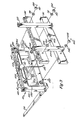
- load sensors 38, 40, 122 and 128 are bolted to crossbar frame 31.
- Load sensors 40, 122 and 128 are substantially identical in construction to load sensor 38 and have axes 162, 164 and 166 corresponding to axis 188.
- Threaded shank 80 passes through upper crossbar 24, and load sensor 38 is held in place on crossbar 24 by means of washer 83 and nut 82 which are mounted on shank 80.
- threaded shank 88 of load sensor 40 passes through lower crossbar 26 and has washer 91 and nut 90 mounted thereon to hold load sensor 38 in place on lower crossbar 26.
- load sensors 12'2 and 128 are held in place on crossbars 24 and 26, respectively, by washers 136 and 140 and by nuts 134 and 138.
- the nuts 82, 90, 134 and 138 are threadably mounted on load sensors 38, 40, 122 and 128 to allow crossbar frame 31 to be easily mounted to and demounted from crossbars 24 and 26 of fork lift truck 10 (see Figure 1).
- the combination of crossbar frame 31 and load sensors 38, 40, 122 and 128 form a mechanically sturdy and weather resistant combination which may be easily installed on existing, commercially available fork lift trucks.
- Load sensors 38, 40, 122 and 128 are connected to junction box 42 by multi-conductor electrical cables 118, 120 t 126 and 132, respectively.
- the function of cables 118, 120, 126 and 132 is to convey electrical signals to and from the respective load sensors 38, 40, 122 and 128.
- the function-of load sensors 38, 40, 122 and 128 is to mechanically connect crossbar frame 31 to the crossbars 24 and 26 and also to transduce or sense the weight of items carried by forks 44 and 112 which are suspended from crossbar frame 31.
- Crossbar frame 31 is preferably a welded rectangular metal frame comprising an upper frame member 32, a lower frame member 34, a right separator 36, and a left separator 110.
- Members 32 and 34 and separators 36 and 110 define a square, empty, open area through which the operator of fork lift truck 10 (see Figure 1) may look so that the vision of said operator is not unduly obstructed.
- Right fork 44 and left fork 112 are suspended from crossbar frame 31 and preferably comprise L-shaped metal bars of the usual, commercially available kind.
- Forks 44 and 112 have generally horizontally disposed lifting surfaces 48 and 116, respectively, onto which items may be placed in order to be carried by fork lift truck 10 (see Figure 1). Forces caused by the weight of items placedon surfaces 48 and 116 are transferred through forks 44 and 112, through frame 31, through sensors 38, 40, 122 and 128, to crossbars 24 and 26 and fork lift truck 10.
- the weight of items placed on surfaces 48 and 116 causes forces to be applied to sensors 38, 40, 122 and 128.
- Sensors 38, 40, 122 and 128 are each exposed to generally vertically oriented shearing forces due to the weight of items placed on surfaces 48 and 116; wherein said shearing forces are generally perpendicular to axes 188, 162, 164 and 166, respectively.
- Sensors 38 and 122 are exposed to generally horizontally oriented tension forces due to the weight of items placed on surfaces 48 and 116; wherein said tension forces are generally parallel to axes 188 and 164, respectively.
- Sensors 40 and 128 are exposed to generally horizontally oriented compression forces due to the weight of items placed on surfaces 48 and 116; wherein said compression forces are generally parallel to axes 162 and 166, respectively.
- the forces applied to sensor 38 are approximately equal to the forces applied to sensor 122 and the forces applied to sensor 40 are approximately equal to the forces applied to sensor 128.
- the applied forces may differ between sensors 40 and 128, and generally horizontally oriented shear forces may be applied to sensors 38, 40, 122 and 128 in planes generally perpendicular to axes 188, 162, 164 and 166, respectively.
- FIG. 4 a magnified view of a portion of shear cell 38 shown in Figure 4 is presented.
- Strain gages 156 and 158 are attached to mounting pad 180.
- Mounting pad 180 is preferably a thin sheet of nonmetallic electrically insulating material attached to deformable member 154.
- Mounting pad 180 with strain gages 156 and 158 attached may be purchased as a commercially available item. In practice, one of the steps in manufacturing shear cell 38 is gluing pad 180 to deformable member 154.
- Strain gage 156 is typical of the overall structure of electrical resistance strain gages which can be used and consists of a strain sensitive conductor 184 placed between electrical contact 182 and electrical contact 186. Strain gage 156 can comprise a thin metallic foil which has been etched to obtain the shape shown. Contacts 182 and 186 are electrically conductive pads to which wires can be soldered. Strain sensitive conductor 184 is preferably a metallic foil formed into non-overlapping elongated loops. The loops of strain sensitive conductor 184 comprise a plurality of elongated portions 185 interconnected by short, wide conductors 187. The elongated portions 185 of the strain sensitive conductor 184 are parallel to the dotted line 190. Note that strain sensitive conductor 184 could alternatively be formed by non-overlapping loops of conductive wire bonded to mounting pad 180. Strain gage 158 is similarly constructed with a strain sensitive conductor 214 having elongated loop portions parallel to dotted line 192.
- strain sensitive conductor 184 is constrained to deform in the same way as that portion of the surface deformable member 154 over which strain sensitive conductor 184 is attached. That is, strain sensitive conductor 184 deforms as if it were a part of the deformable member 154.
- Dotted line 188 is a projection from the neutral axis of deformable member 154.
- the neutral axis of deformable member 154 is colinear with the geometric axis of deformable member 154 and deformable member 154 is formed as a solid circular cylinder.
- Line 190 intersects with line 188 at an angle 194 of approximately 45°.
- Line 192 intersects with line 188 at an angle 196 of approximately 45°.
- the line 188 is generally horizontal when shear cell 38 is mounted between frame 31 and cross bar 24, as shown in Figure 1.
- the size of angles 194 and 196 is chosen to maximize the sensitivity of strain gages 156 and 158 when deformable member 154 is in vertical shear.
- Strain gage 156 functions by changing the electrical resistance in strain sensitive conductor 184 between contact 182 and 186.
- the electrical resistance of the elongated portions 185 of strain sensitive conductor 184 changes when mechanical strain causes the elongated portions 185 to change in length and cross-section. Resistance changes in strain gages 156 are maximized when mechanical strain occurs in a direction parallel to line 190 which is parallel to the elongated portions 185 of strain sensitive conductor 184.
- the electrical resistance of strain gage 158 is particularly sensitive to mechanical strains occurring parallel to line 192. Mechanical strain due to vertical shear is maximum in deformable member 154 at angles which are approximately 45° from the line 188.
- Wires 198, 200, 202, and 204 comprise cable 118 and communicate electrical signals with shear cell 38.
- Wire 198 is soldered to and makes electrical contact with contact 182 of strain gage 156.
- wire 200 contacts strain gage 158.
- a hollow cavity 212 is defined in the space between the deformable member 154 and shroud 152. Cavity 212 provides space for the routing of wires used to interconnect the strain gages and can be filled with an epoxy or silicone potting compound to prevent movement of the wires used and to anchor cable 118. The use of such a potting compound inside cavity 212 also protects the strain gages from moisture, mechanical abrasion and other damaging outside influences.
- Strain gages 160 and 244 are attached to mounting pad 242 which is attached to deformable member 154.
- Mounting pad 242 is preferably a thin sheet of electrically insulating material similar to pad 180.
- Dotted line 246 is projected from the neutral axis of deformable member 154.
- Strain gage 160 has a strain sensitive conductor 256 having elongated portions which are parallel to dotted 248. Line 248 intersects line 246 at an angle 252 of approximately 45°, as shown.
- Strain gage 244 has a strain sensitive conductor 258 having elongated portions parallel to dotted line 250.
- Line 250 intersects line 246 at an angle 254 of approximately 45°.
- the sizes of angles 252 and 254 are chosen to maximize the response of strain gages 160 and * 244 to vertical shear strain.
- angles 252 and 196 open inwardly along line 246 towards threaded shank 80.
- angles 254 and 194 of Figure 4 open outwardly along line 188 towards flange 86. It will be seen that strain gages 156 and 158 perform the same function with respect to strain gages 160 and 244 in terms of measuring vertical shear.
- Wires 202, 204, 208, 210, and 240 are used to communicate electrical signals to strains gages 160 and 244. Taken together, strain gages 156, 158, 160, and 244 together with wires 206, 208, 210, and 240 comprise a Wheatstone bridge configuration. Wires 198, 200, 202 and 204 make contact with the nodes of the Wheatstone bridge configuration.
- FIG. 6 stress analysis diagram of a transducer is thereshown.
- One side of a transducer is represented as a rectangle in A of Figure 6 in an unstressed condition with respect to vertical loading.
- the rectangle includes sides 302, 304, 306, and 308, along with diagonals 310 and 312.
- the dotted line 300 represents the neutral axis.
- one side of the transducer is represented in a stressed condition with respect to vertical loading and includes sides 302', 304', 306', 3Q8', and diagonals 310' and 312'.
- the diagonals represent maximum compressive and tension loading in the transducer due to shear and of course, it will be appreciated that the direction of loading is approximately 45° relative to the neutral axis.
- Figure 7 shows an overall schematic diagram for the circuitry used in which electrical resistance strain gages have been represented symbolically as their equivalent resistors. Strain gages 156, 158, 244, and 160 have been symbolized by resistances Rl, R2, R3, and R4, respectively. Rl, R2, R3, and R4 form a Wheatstone bridge which is excited by a voltage source which supplies a voltage V. The voltage source may supply direct or alternating current. A bridge output voltage El is generated according to the equation:
- resistances Rl, R2, R3, and R4 are constructed so as to have nearly the same electrical resistance when no weight is present on fork 52.
- the strain gages corresponding to Rl, R2, R3, and R4 should have nearly identical gage factors, that is, the resistance of each strain gage should change by an identical amount when each strain gage is exposed to the same strain. If each strain gage has an identical temperature coefficient of resistance, no substantial change in El will be noticed when the ambient temperature changes. If Rl, R2, R3, and R4 are approximately equal and the change in each of those resistances when fork 52 is loaded are small compared to those resistances, then the following proportionality is approximately correct (note that " 6 " means "change in" and K is a proportionality constant):
- a Wheatstone bridge comprised of resistors Rll, R12, R13, and R14 which generates an output voltage E2 symbolizes shear cell 40.
- a Wheatstone bridge comprised of resistors R21, R22, R23, and R24 which have a bridge output voltage E3 symbolizes shear cell 122.
- Resistors R31, R32, R33, and R34 comprise a Wheatstone bridge having an output voltage E4 symbolizing shear cell 128.
- Shear cells 38, 40, 122, and 128 have substantially the same mechanical structure and exhibit the same type of electrical behavior when stressed in the same way.
- Amplifier Al inverts and amplifies the bridge output signal El. The signals are summed before reading the amplifier and this signal is supplied to the output display.
- the output display corresponds to display 30 of Figure 1 and presents a mathematical summation of the vertical shear forces measured by the shear cells 38, 40, 122, and 128 which is equal to the weight of the items placed on fork 52.
- shear cells 38, 40, 122, and 128 Placing weights against tine surfaces 46 and 114 may result in horizontal forces being seen by shear cells 38, 40, 122, and 128.
- the theory is that the summation of the vertical shearing forces seen by shear cells 38, 40, 122, and 128 is equal to the weight of items placed on the fork 52.
- shear cells 38, 40, 122, and 128 are designed to be insensitive to types of loading other than vertical shear forces.
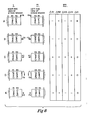
- Rows (a) through (e) of Figure 8 represent different types of force and moment loading which may be applied to shear cell 38. Because of the similarity among the shear cells, Figure 8 also represents the behavior of shear cells 40, 122, and 128.
- Column I contains symbolic diagrams of the side of shear cell 38 that was shown in Figure 4.
- Column II contains a symbolic diagrams of the side of shear cell 38 shown in Figure 5.
- Column III is a tabulation of change in resistance values and change in voltage values as used in Equation 2. The contents of Column III have been symbolized by "+” meaning an increase in resistance or voltage, "-” meaning a decrease in voltage or resistance, and "o" meaning no change in resistance or voltage.
- Row (a) shows that voltage El decreases when a vertical force F is applied to shear cell 38.
- a vertical force F corresponds to a force caused by the weight of items placed on fork 52. Shearing forces caused by this force F are sensed by shear cell 38 and produce a change in voltage El which results in an indication by weight by the output display.
- shear cells 38, ' 40, 122, and 128 are constructed so as to be sensitive to vertical forces such as force F shown in Row (a) which result from the placing of items having weight on fork 52.
- Row (b) shows that no change in El occurs when a bending moment M is applied to shear cell 38.
- a moment M corresponds to the bending moment produced by placing items having weight on fork 52.
- Moment M is expected to increase as such items are moved away from the fork lift truck 10 along the tine lifting surfaces 48 and 116. Since it is desirable not to have display 30 affected in any way by the position of items on fork 52, the fork lift scale has been designed to be insensitive to bending moments.
- the lower transducers are subjected to compressive force which may be considered a reaction force brought about by placing a weight on the tines away from the carriage. Since El is unaffected by moment M in Row (b), the output display does not reflect the position of items placed on fork 52.
- Row (c) shows that no change in El occurs when a horizontal force F is applied to shear cell 38.
- Tension force does occur on the upper transducers and may be considered a' reaction force by placing weights on the tines away from the carriage.
- Such a horizontal force F may result when items placed on a fork 52 touch the back tine surfaces 46 and 114.
- Such a horizontal force F may also result from placing items on tine lifting surfaces 48 and 116 and may be a function of the distance of such items from fork lift truck 10.
- Row (c) illustrates that the output display is unaffected by force F. Also, a force F shown will not cause a change in the output display.
- Row (d) shows that no change in El occurs when a torque or twisting moment T is applied to shear cell 38.
- Torque T of Row (d) may result when the weight carried by tines 44 and 112 is-unequally distributed.
- the output display is unaffected by such an unequal weight distribution and is sensitive only to the amount of weight carried by fork 52.
- the torque vector T of Row (d) is equivalent to a counterclockwise twist applied to the threaded shank 80 of Figure 2.
- the described embodiment is directed to meeting, at least in part, the following objects:
Landscapes
- Physics & Mathematics (AREA)
- General Physics & Mathematics (AREA)
- Forklifts And Lifting Vehicles (AREA)
- Measurement Of Force In General (AREA)
Applications Claiming Priority (2)
| Application Number | Priority Date | Filing Date | Title |
|---|---|---|---|
| US18080280A | 1980-08-25 | 1980-08-25 | |
| US180802 | 1980-08-25 |
Publications (3)
| Publication Number | Publication Date |
|---|---|
| EP0046692A2 true EP0046692A2 (fr) | 1982-03-03 |
| EP0046692A3 EP0046692A3 (en) | 1982-03-17 |
| EP0046692B1 EP0046692B1 (fr) | 1986-04-23 |
Family
ID=22661816
Family Applications (1)
| Application Number | Title | Priority Date | Filing Date |
|---|---|---|---|
| EP19810303881 Expired EP0046692B1 (fr) | 1980-08-25 | 1981-08-25 | Dispositif de pesage pour un chariot élévateur à fourche |
Country Status (5)
| Country | Link |
|---|---|
| EP (1) | EP0046692B1 (fr) |
| AU (1) | AU554361B2 (fr) |
| CA (1) | CA1166656A (fr) |
| DE (1) | DE3174462D1 (fr) |
| ES (1) | ES505007A0 (fr) |
Cited By (7)
| Publication number | Priority date | Publication date | Assignee | Title |
|---|---|---|---|---|
| GB2127981A (en) * | 1982-09-29 | 1984-04-18 | James Ind Ltd | Invalid hoists |
| FR2651880A1 (fr) * | 1989-09-11 | 1991-03-15 | Odru Robert | Procede et dispositif de pesage d'une charge. |
| AU615240B2 (en) * | 1988-12-09 | 1991-09-26 | Greer, Gerald L. | Weighing scale for transporter loads |
| EP0500213A1 (fr) * | 1991-02-19 | 1992-08-26 | Toter, Inc. | Dispositif et procédé pour peser le contenu d'un récipient à ordures |
| WO1993017308A1 (fr) * | 1992-02-27 | 1993-09-02 | Mettler-Toledo B.V. | Dispositif de pesage mobile d'un article |
| WO1997000427A1 (fr) * | 1995-06-16 | 1997-01-03 | Weigh-Tronix, Inc. | Balance sensible a la charge et cellule de pesage a deux capteurs destinee a etre utilisee avec ladite balance |
| FR2747778A1 (fr) * | 1996-04-22 | 1997-10-24 | Balea | Tablier peseur monobloc autonome |
Families Citing this family (2)
| Publication number | Priority date | Publication date | Assignee | Title |
|---|---|---|---|---|
| DE3923198A1 (de) * | 1989-07-13 | 1991-01-24 | Moba Electronic Mobil Automat | Traktorwaage |
| CA2032983C (fr) * | 1990-12-21 | 1999-09-07 | Allan Bowman | Systeme de pesage du chargement des camions a ordures |
Family Cites Families (8)
| Publication number | Priority date | Publication date | Assignee | Title |
|---|---|---|---|---|
| US2940746A (en) * | 1953-10-21 | 1960-06-14 | Union Metal Mfg Co | Portable scale mechanism |
| US2935213A (en) * | 1958-12-19 | 1960-05-03 | Int Harvester Co | Fork lift vehicle weighing scale |
| US3059710A (en) * | 1959-07-13 | 1962-10-23 | Baldwin Lima Hamilton Corp | Indirect measurement of vertical forces |
| US3196966A (en) * | 1964-01-13 | 1965-07-27 | Goodman Mfg Co | Weighing apparatus |
| US3320569A (en) * | 1965-02-17 | 1967-05-16 | Instron Corp | Shear load cell |
| SE311573B (fr) * | 1967-02-08 | 1969-06-16 | Bofors Ab | |
| US3949603A (en) * | 1974-07-01 | 1976-04-13 | Hottinger Baldwin Measurements | Strain gage transducer |
| FR2356913A1 (fr) * | 1976-06-30 | 1978-01-27 | Valentine Cie Vernis | Dispositif de dosage, notamment pour peintures |
-
1981
- 1981-08-24 CA CA000384503A patent/CA1166656A/fr not_active Expired
- 1981-08-25 ES ES505007A patent/ES505007A0/es active Granted
- 1981-08-25 DE DE8181303881T patent/DE3174462D1/de not_active Expired
- 1981-08-25 AU AU74494/81A patent/AU554361B2/en not_active Ceased
- 1981-08-25 EP EP19810303881 patent/EP0046692B1/fr not_active Expired
Cited By (12)
| Publication number | Priority date | Publication date | Assignee | Title |
|---|---|---|---|---|
| GB2127981A (en) * | 1982-09-29 | 1984-04-18 | James Ind Ltd | Invalid hoists |
| AU615240B2 (en) * | 1988-12-09 | 1991-09-26 | Greer, Gerald L. | Weighing scale for transporter loads |
| FR2651880A1 (fr) * | 1989-09-11 | 1991-03-15 | Odru Robert | Procede et dispositif de pesage d'une charge. |
| EP0500213A1 (fr) * | 1991-02-19 | 1992-08-26 | Toter, Inc. | Dispositif et procédé pour peser le contenu d'un récipient à ordures |
| WO1993017308A1 (fr) * | 1992-02-27 | 1993-09-02 | Mettler-Toledo B.V. | Dispositif de pesage mobile d'un article |
| FR2688062A1 (fr) * | 1992-02-27 | 1993-09-03 | Mettler Toledo Bv | Dispositif pour le pesage mobile d'un objet. |
| GB2270170A (en) * | 1992-02-27 | 1994-03-02 | Mettler Toledo Bv | Device for the mobile weighing of an article |
| BE1006154A3 (nl) * | 1992-02-27 | 1994-05-24 | Mettler Toledo Bv | Inrichting voor het mobiel wegen van een voorwerp. |
| GB2270170B (en) * | 1992-02-27 | 1995-03-22 | Mettler Toledo Bv | Device for weighing a moving article |
| WO1997000427A1 (fr) * | 1995-06-16 | 1997-01-03 | Weigh-Tronix, Inc. | Balance sensible a la charge et cellule de pesage a deux capteurs destinee a etre utilisee avec ladite balance |
| FR2747778A1 (fr) * | 1996-04-22 | 1997-10-24 | Balea | Tablier peseur monobloc autonome |
| EP0803717A1 (fr) * | 1996-04-22 | 1997-10-29 | Balea S.A. | Tablier peseur monobloc autonome |
Also Published As
| Publication number | Publication date |
|---|---|
| ES8302302A1 (es) | 1983-01-01 |
| EP0046692A3 (en) | 1982-03-17 |
| AU7449481A (en) | 1982-03-04 |
| EP0046692B1 (fr) | 1986-04-23 |
| AU554361B2 (en) | 1986-08-21 |
| DE3174462D1 (en) | 1986-05-28 |
| ES505007A0 (es) | 1983-01-01 |
| CA1166656A (fr) | 1984-05-01 |
Similar Documents
| Publication | Publication Date | Title |
|---|---|---|
| US4421186A (en) | Fork lift scale | |
| EP2789997B1 (fr) | Dispositif de détection de charge | |
| US3938603A (en) | Constant moment weigh scale with floating flexure beam | |
| US4020911A (en) | Load cell scale | |
| US4478089A (en) | Tri-axial force transducer for a manipulator gripper | |
| US2935213A (en) | Fork lift vehicle weighing scale | |
| US3927560A (en) | Moment desensitization of load cells | |
| EP2189766B1 (fr) | Mesure d'une charge de roue et/ou d'essieu de véhicules routiers | |
| US2899191A (en) | Electrically actuated weighing device | |
| CA1122032A (fr) | Cellule de pesage | |
| US5872319A (en) | Helical load cell | |
| US5090493A (en) | Load cells and scales therefrom | |
| EP0046692B1 (fr) | Dispositif de pesage pour un chariot élévateur à fourche | |
| US4621533A (en) | Tactile load sensing transducer | |
| US5824963A (en) | Lifting device employing a weight integrative weighing system | |
| US4385527A (en) | Aircraft weighing systems | |
| SE439990B (sv) | Lastcell | |
| WO1999017087A1 (fr) | Cellule dynamometrique pour mesurer la torsion | |
| US5228527A (en) | Force measurement assembly | |
| JP2699096B2 (ja) | 測定装置 | |
| US20110127091A1 (en) | Planar Beam Load Cell Assembly | |
| US5783755A (en) | Lifting device employing an equalizer system to reduce weight measurement error | |
| US4457385A (en) | Platform scale with bendable load sensing beam | |
| US4433586A (en) | Electronic cable load gauge | |
| US3966003A (en) | Weighing apparatus |
Legal Events
| Date | Code | Title | Description |
|---|---|---|---|
| PUAI | Public reference made under article 153(3) epc to a published international application that has entered the european phase |
Free format text: ORIGINAL CODE: 0009012 |
|
| PUAL | Search report despatched |
Free format text: ORIGINAL CODE: 0009013 |
|
| AK | Designated contracting states |
Designated state(s): BE DE FR GB NL |
|
| AK | Designated contracting states |
Designated state(s): BE DE FR GB NL |
|
| 17P | Request for examination filed |
Effective date: 19820902 |
|
| GRAA | (expected) grant |
Free format text: ORIGINAL CODE: 0009210 |
|
| AK | Designated contracting states |
Kind code of ref document: B1 Designated state(s): BE DE FR GB NL |
|
| PG25 | Lapsed in a contracting state [announced via postgrant information from national office to epo] |
Ref country code: NL Effective date: 19860423 Ref country code: FR Free format text: THE PATENT HAS BEEN ANNULLED BY A DECISION OF A NATIONAL AUTHORITY Effective date: 19860423 Ref country code: BE Effective date: 19860423 |
|
| REF | Corresponds to: |
Ref document number: 3174462 Country of ref document: DE Date of ref document: 19860528 |
|
| EN | Fr: translation not filed | ||
| NLV1 | Nl: lapsed or annulled due to failure to fulfill the requirements of art. 29p and 29m of the patents act | ||
| PLBE | No opposition filed within time limit |
Free format text: ORIGINAL CODE: 0009261 |
|
| STAA | Information on the status of an ep patent application or granted ep patent |
Free format text: STATUS: NO OPPOSITION FILED WITHIN TIME LIMIT |
|
| 26N | No opposition filed | ||
| PG25 | Lapsed in a contracting state [announced via postgrant information from national office to epo] |
Ref country code: DE Effective date: 19870501 |
|
| GBPC | Gb: european patent ceased through non-payment of renewal fee | ||
| REG | Reference to a national code |
Ref country code: GB Ref legal event code: 728C |
|
| REG | Reference to a national code |
Ref country code: GB Ref legal event code: 728A |
|
| PGFP | Annual fee paid to national office [announced via postgrant information from national office to epo] |
Ref country code: GB Payment date: 19950727 Year of fee payment: 15 |
|
| PG25 | Lapsed in a contracting state [announced via postgrant information from national office to epo] |
Ref country code: GB Effective date: 19960825 |
|
| GBPC | Gb: european patent ceased through non-payment of renewal fee |
Effective date: 19960825 |