EP0046744A1 - Regulierbarer Brausekopf - Google Patents
Regulierbarer Brausekopf Download PDFInfo
- Publication number
- EP0046744A1 EP0046744A1 EP81850142A EP81850142A EP0046744A1 EP 0046744 A1 EP0046744 A1 EP 0046744A1 EP 81850142 A EP81850142 A EP 81850142A EP 81850142 A EP81850142 A EP 81850142A EP 0046744 A1 EP0046744 A1 EP 0046744A1
- Authority
- EP
- European Patent Office
- Prior art keywords
- shower head
- water
- plungers
- housing
- openings
- Prior art date
- Legal status (The legal status is an assumption and is not a legal conclusion. Google has not performed a legal analysis and makes no representation as to the accuracy of the status listed.)
- Granted
Links
- XLYOFNOQVPJJNP-UHFFFAOYSA-N water Substances O XLYOFNOQVPJJNP-UHFFFAOYSA-N 0.000 claims abstract description 44
- 238000007789 sealing Methods 0.000 claims abstract description 10
- 230000007423 decrease Effects 0.000 claims description 2
- 238000006073 displacement reaction Methods 0.000 claims 1
- 230000000694 effects Effects 0.000 abstract description 5
- 230000003247 decreasing effect Effects 0.000 description 3
- 230000000717 retained effect Effects 0.000 description 2
- 230000002542 deteriorative effect Effects 0.000 description 1
- 238000012986 modification Methods 0.000 description 1
- 230000004048 modification Effects 0.000 description 1
- 239000003566 sealing material Substances 0.000 description 1
Images
Classifications
-
- B—PERFORMING OPERATIONS; TRANSPORTING
- B05—SPRAYING OR ATOMISING IN GENERAL; APPLYING FLUENT MATERIALS TO SURFACES, IN GENERAL
- B05B—SPRAYING APPARATUS; ATOMISING APPARATUS; NOZZLES
- B05B1/00—Nozzles, spray heads or other outlets, with or without auxiliary devices such as valves, heating means
- B05B1/30—Nozzles, spray heads or other outlets, with or without auxiliary devices such as valves, heating means designed to control volume of flow, e.g. with adjustable passages
- B05B1/3033—Nozzles, spray heads or other outlets, with or without auxiliary devices such as valves, heating means designed to control volume of flow, e.g. with adjustable passages the control being effected by relative coaxial longitudinal movement of the controlling element and the spray head
- B05B1/3086—Nozzles, spray heads or other outlets, with or without auxiliary devices such as valves, heating means designed to control volume of flow, e.g. with adjustable passages the control being effected by relative coaxial longitudinal movement of the controlling element and the spray head the controlling element being a grooved body, which is movable in the outlet orifice
-
- B—PERFORMING OPERATIONS; TRANSPORTING
- B05—SPRAYING OR ATOMISING IN GENERAL; APPLYING FLUENT MATERIALS TO SURFACES, IN GENERAL
- B05B—SPRAYING APPARATUS; ATOMISING APPARATUS; NOZZLES
- B05B1/00—Nozzles, spray heads or other outlets, with or without auxiliary devices such as valves, heating means
- B05B1/14—Nozzles, spray heads or other outlets, with or without auxiliary devices such as valves, heating means with multiple outlet openings; with strainers in or outside the outlet opening
- B05B1/16—Nozzles, spray heads or other outlets, with or without auxiliary devices such as valves, heating means with multiple outlet openings; with strainers in or outside the outlet opening having selectively- effective outlets
-
- B—PERFORMING OPERATIONS; TRANSPORTING
- B05—SPRAYING OR ATOMISING IN GENERAL; APPLYING FLUENT MATERIALS TO SURFACES, IN GENERAL
- B05B—SPRAYING APPARATUS; ATOMISING APPARATUS; NOZZLES
- B05B1/00—Nozzles, spray heads or other outlets, with or without auxiliary devices such as valves, heating means
- B05B1/14—Nozzles, spray heads or other outlets, with or without auxiliary devices such as valves, heating means with multiple outlet openings; with strainers in or outside the outlet opening
- B05B1/18—Roses; Shower heads
Definitions
- the present invention refers to a shower head comprising a hollow housing for the passage of water, a sprinkle device mounted at the outlet end of said housing and a rotatable member cooperating with said sprinkle device for adjusting the through-flow area of the shower head.
- the amount of water used when showering may be reduced without seriously deteriorating the shower effect. It is also desired that the shower pattern, in spite of a reduced amount of water, may be adjusted from consisting of many very thin "needle sharp" jets to a lesser number of turbulent jets with a massaging effect.
- Hand held showers with an adjustable shower head are previously known (e.g. US patent specification 3.116.880) wherein the water flow may be adjusted and even completely closed off by means of a nut screwed onto the outer side of the shower head. This takes place by means of a valve body connected to said nut and moving towards and away from, respectively, the outlet end of the inlet conduit in the shower head and throttling the water flow to a larger or lesser degree.
- This design does not solve the above mentioned problem since after the throttling the water will flow out into a larger space, being subjected to a reduction in pressure, before being distributed over the jet openings.
- the nozzle plate is fixedly mounted and is surrounded by a rotatable member moveable towards and away from said plate so that an annular opening around the nozzle plate will be closed or opened. Adjustment of the water flow through the nozzle plate can be obtained only by increasing or decreasing the annular slot, which neither leads to a reduction of the water consumption nor to a positive change in the shower pattern.
- the object of the present invention is to provide a shower head of 'the kind mentioned hereinbefore, wherein a good shower effect with maintained distribution of the water may be obtained also with low rates of flow of the water.
- Another object of the invention is to provide the possibility of varying the shower jet in a simple manner from very fine "needle sharp" jets to a lesser number of more forceful turbulent jets.
- said sprinkle device comprises an insert axially displaceable by said rotating member and comprising a number of plunger elements with increasing cross-sectional area in the direction of flow of the water, said plungers being displaceable each in an opening in the housing, said openings having a corresponding increase of the cross-sectional area in the direction of flow of the water, that said plungers and/or the walls of said openings are formed with channel-shaped grooves which form passages for the water between the housing and said plungers and that a sealing member is provided in each opening intended to seal against the respective plungers.
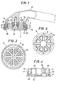
- the shower head 1 comprises a housing 2, which is fixedly mounted by means of a screw 3 to a hollow handle 4, which may be connected to a flexible supply conduit in conventional manner.
- the housing 2 has a cylindrical outer wall provided with external, threads 5.
- a number of openings 6 with a sector-shaped cross-section extend axially through the housing 2 and are arranged uniformly around the middle portion 7 of the housing.
- the openings 6 have their pointed ends oriented towards said middle portion 7 and their cross-sectional area increases slightly in the direction towards the outlet end of the housing 2.
- an insert 8 which is retained by a nut 9 screwed onto the external threading of the housing and having an inwardly directed flange 10 abutting against radial projections 11 of the insert 8.
- the insert 8 is provided with a number of plunger elements 12 corresponding to the number of the openings 6, one plunger 12 being received in each of the openings 6.
- the elements 12 have a cross-sectional shape corresponding to that of the openings 6 and have a cross-sectional area which increases slightly in the direction of flow of the water.
- the plungers 12 may be brought to lie against the walls of the openings 6.
- the openings 6 and the plungers 12 may of course have any other cross-sectional shape and be positioned in other ways than what is shown in the drawing as an example only.
- channel-shaped grooves 13 On the outer side of the plungers 12 there are formed channel-shaped grooves 13, which form passages for the water between the housing 2 and the insert 8. As an alternative, similar grooves may be arranged in the walls of the openings, or such grooves can be arranged both in the walls of the openings and on the outside of the elements 12.
- the grooves 13 preferably have a decreasing depth and/or width in the direction of flow of the water.
- a sealing washer 14 provided with openings corresponding to the openings 6 and adapted to seal against the plungers 12. The sealing washer 14 is retained against a shoulder in the housing 2 by means of a pressure plate 15 and a locking ring 16 outside of the plate 15.
- the sealing washer 14 prevents the passage of water between the housing 2 and the insert 8 in other places than through the channels 13, and when the insert is moved further into the housing the soft sealing material may partly be pressed into the grooves 13, whereby the through- flow area for the water is further increased.
- the reduction of the area obtained in this way may be sufficient even if the channels 13 have a uniform width and depth along their lengths.
- the arrangement operates in the following manner.
- the insert 8 By tightening the nut 9 the insert 8 will be pressed inwardly in the housing 2, whereby the through-flow area for the water will be decreased. This will cause the velocity of the water in the shower head to increase.
- the nut 9 is rotated in the opposite direction, whereby the insert 8 will be pressed outwardly by the water as far as the position of the nut will allow. This will cause an increase of the through-flow area.
- the water consumption during showering may be reduced, since even at low rates of flow of the water it will be possible to obtain a sufficient velocity of the water jets and thereby the desired shower effect.
- the elements 12 are formed, at their arcuate part 17, with a conical projection 18.
- the -channel-shaped grooves 13 extend along said conical projection with a reduced depth and/or width.
- the insert 8 is rotatably and axially non-displaceably mounted in the rotatable member 9.
Landscapes
- Nozzles (AREA)
- Massaging Devices (AREA)
- Paper (AREA)
Priority Applications (1)
| Application Number | Priority Date | Filing Date | Title |
|---|---|---|---|
| AT81850142T ATE10260T1 (de) | 1980-08-26 | 1981-08-26 | Regulierbarer brausekopf. |
Applications Claiming Priority (2)
| Application Number | Priority Date | Filing Date | Title |
|---|---|---|---|
| SE8005954A SE449702B (sv) | 1980-08-26 | 1980-08-26 | Reglerbart duschhuvud |
| SE8005954 | 1980-08-26 |
Publications (2)
| Publication Number | Publication Date |
|---|---|
| EP0046744A1 true EP0046744A1 (de) | 1982-03-03 |
| EP0046744B1 EP0046744B1 (de) | 1984-11-14 |
Family
ID=20341596
Family Applications (1)
| Application Number | Title | Priority Date | Filing Date |
|---|---|---|---|
| EP81850142A Expired EP0046744B1 (de) | 1980-08-26 | 1981-08-26 | Regulierbarer Brausekopf |
Country Status (5)
| Country | Link |
|---|---|
| US (1) | US4427155A (de) |
| EP (1) | EP0046744B1 (de) |
| AT (1) | ATE10260T1 (de) |
| DE (1) | DE3167212D1 (de) |
| SE (1) | SE449702B (de) |
Cited By (5)
| Publication number | Priority date | Publication date | Assignee | Title |
|---|---|---|---|---|
| RU2185250C1 (ru) * | 2001-02-22 | 2002-07-20 | Порядков Леонид Федорович | Оздоровительно-лечебная душевая установка |
| RU2188715C1 (ru) * | 2001-02-22 | 2002-09-10 | Порядков Леонид Федорович | Душевая насадка для оздоровительно-лечебного душа |
| RU2221650C1 (ru) * | 2002-05-17 | 2004-01-20 | Порядков Леонид Федорович | Душевая насадка для температурного массажа |
| RU2241547C2 (ru) * | 2000-02-09 | 2004-12-10 | Хансгроэ Аг | Душевая головка |
| RU2598470C1 (ru) * | 2012-08-22 | 2016-09-27 | Айдиел Стэндед Интернэшнл Бвба | Душевая лейка с пружинящей водонаправляющей прокладкой |
Families Citing this family (2)
| Publication number | Priority date | Publication date | Assignee | Title |
|---|---|---|---|---|
| US7543371B2 (en) * | 2004-06-23 | 2009-06-09 | Hitachi Global Storage Technologies Netherlands B.V. | Apparatus for a disk drive actuator pivot set height tooling with an active servo compensation |
| US10022734B2 (en) * | 2016-11-14 | 2018-07-17 | Chronomite Laboratories, Inc. | Variable dual flow fitting |
Citations (6)
| Publication number | Priority date | Publication date | Assignee | Title |
|---|---|---|---|---|
| US2790677A (en) * | 1955-09-13 | 1957-04-30 | Sloan Valve Co | Automatic self-cleaning shower heads |
| US3116880A (en) * | 1962-10-09 | 1964-01-07 | Sam E Kuiken | Spray head assembly |
| US3403860A (en) * | 1965-10-29 | 1968-10-01 | Shames Harold | Adjustable spray shower heads |
| US3876151A (en) * | 1973-08-27 | 1975-04-08 | Alsons Corp | Jet regulating shower head |
| US3995812A (en) * | 1975-08-13 | 1976-12-07 | Producers Specialty & Mfg. Co., Inc. | Adjustment assembly for shower heads |
| DE2830201A1 (de) * | 1978-07-10 | 1980-01-24 | Tenge Rietberg Carl Friedrich | Handbrause |
Family Cites Families (2)
| Publication number | Priority date | Publication date | Assignee | Title |
|---|---|---|---|---|
| US1830694A (en) | 1928-09-24 | 1931-11-03 | Speakman Co | Shower head |
| US2756108A (en) | 1954-02-23 | 1956-07-24 | Nylon Maid Inc | Shower head |
-
1980
- 1980-08-26 SE SE8005954A patent/SE449702B/sv not_active IP Right Cessation
-
1981
- 1981-08-26 DE DE8181850142T patent/DE3167212D1/de not_active Expired
- 1981-08-26 EP EP81850142A patent/EP0046744B1/de not_active Expired
- 1981-08-26 AT AT81850142T patent/ATE10260T1/de not_active IP Right Cessation
- 1981-08-26 US US06/296,487 patent/US4427155A/en not_active Expired - Fee Related
Patent Citations (6)
| Publication number | Priority date | Publication date | Assignee | Title |
|---|---|---|---|---|
| US2790677A (en) * | 1955-09-13 | 1957-04-30 | Sloan Valve Co | Automatic self-cleaning shower heads |
| US3116880A (en) * | 1962-10-09 | 1964-01-07 | Sam E Kuiken | Spray head assembly |
| US3403860A (en) * | 1965-10-29 | 1968-10-01 | Shames Harold | Adjustable spray shower heads |
| US3876151A (en) * | 1973-08-27 | 1975-04-08 | Alsons Corp | Jet regulating shower head |
| US3995812A (en) * | 1975-08-13 | 1976-12-07 | Producers Specialty & Mfg. Co., Inc. | Adjustment assembly for shower heads |
| DE2830201A1 (de) * | 1978-07-10 | 1980-01-24 | Tenge Rietberg Carl Friedrich | Handbrause |
Cited By (5)
| Publication number | Priority date | Publication date | Assignee | Title |
|---|---|---|---|---|
| RU2241547C2 (ru) * | 2000-02-09 | 2004-12-10 | Хансгроэ Аг | Душевая головка |
| RU2185250C1 (ru) * | 2001-02-22 | 2002-07-20 | Порядков Леонид Федорович | Оздоровительно-лечебная душевая установка |
| RU2188715C1 (ru) * | 2001-02-22 | 2002-09-10 | Порядков Леонид Федорович | Душевая насадка для оздоровительно-лечебного душа |
| RU2221650C1 (ru) * | 2002-05-17 | 2004-01-20 | Порядков Леонид Федорович | Душевая насадка для температурного массажа |
| RU2598470C1 (ru) * | 2012-08-22 | 2016-09-27 | Айдиел Стэндед Интернэшнл Бвба | Душевая лейка с пружинящей водонаправляющей прокладкой |
Also Published As
| Publication number | Publication date |
|---|---|
| SE449702B (sv) | 1987-05-18 |
| EP0046744B1 (de) | 1984-11-14 |
| ATE10260T1 (de) | 1984-11-15 |
| US4427155A (en) | 1984-01-24 |
| DE3167212D1 (en) | 1984-12-20 |
| SE8005954L (sv) | 1982-02-27 |
Similar Documents
| Publication | Publication Date | Title |
|---|---|---|
| US5246169A (en) | Shower head | |
| CA1044731A (en) | Pulsating fluid spray device | |
| US5397064A (en) | Shower head with variable flow rate, pulsation and spray pattern | |
| US5647541A (en) | Water flow control device for rotary sprinkler | |
| EP0646417B1 (de) | Brausekopf mit Mehrfachfunktion | |
| US4629125A (en) | Spray nozzle | |
| US5217166A (en) | Rotor nozzle for a high-pressure cleaning device | |
| US4573639A (en) | Shower head | |
| US4669666A (en) | Shower head | |
| US4101075A (en) | Pulsating fluid spray device | |
| US4588130A (en) | Showerhead | |
| US4898332A (en) | Adjustable rotary stream sprinkler unit | |
| US4867379A (en) | Rotary stream sprinkler unit | |
| EP0888193B1 (de) | Auf vorgegebene sprühbilder einstellbarer statischer sprinkler | |
| US4324364A (en) | Adjustable shower head | |
| US4394969A (en) | Showerhead control | |
| JPH02133805A (ja) | 流量制限器 | |
| US4427155A (en) | Adjustable shower head | |
| US5137048A (en) | Tub/shower diverter valve | |
| CA2979011C (en) | Variable dual flow fitting | |
| US4718607A (en) | Atomized liquid spray orifice | |
| US4497444A (en) | Shower head | |
| US3210013A (en) | Shower head | |
| US2658799A (en) | Shower head with volume control | |
| CN210673164U (zh) | 双喷头淋浴套装 |
Legal Events
| Date | Code | Title | Description |
|---|---|---|---|
| PUAI | Public reference made under article 153(3) epc to a published international application that has entered the european phase |
Free format text: ORIGINAL CODE: 0009012 |
|
| AK | Designated contracting states |
Designated state(s): AT BE CH DE FR GB IT LU NL |
|
| 17P | Request for examination filed |
Effective date: 19820415 |
|
| ITF | It: translation for a ep patent filed | ||
| GRAA | (expected) grant |
Free format text: ORIGINAL CODE: 0009210 |
|
| AK | Designated contracting states |
Designated state(s): AT BE CH DE FR GB IT LI LU NL |
|
| PG25 | Lapsed in a contracting state [announced via postgrant information from national office to epo] |
Ref country code: BE Effective date: 19841114 |
|
| REF | Corresponds to: |
Ref document number: 10260 Country of ref document: AT Date of ref document: 19841115 Kind code of ref document: T |
|
| REF | Corresponds to: |
Ref document number: 3167212 Country of ref document: DE Date of ref document: 19841220 |
|
| ET | Fr: translation filed | ||
| PG25 | Lapsed in a contracting state [announced via postgrant information from national office to epo] |
Ref country code: LU Free format text: LAPSE BECAUSE OF NON-PAYMENT OF DUE FEES Effective date: 19850831 |
|
| PLBE | No opposition filed within time limit |
Free format text: ORIGINAL CODE: 0009261 |
|
| STAA | Information on the status of an ep patent application or granted ep patent |
Free format text: STATUS: NO OPPOSITION FILED WITHIN TIME LIMIT |
|
| 26N | No opposition filed | ||
| ITTA | It: last paid annual fee | ||
| PGFP | Annual fee paid to national office [announced via postgrant information from national office to epo] |
Ref country code: AT Payment date: 19930930 Year of fee payment: 13 |
|
| PG25 | Lapsed in a contracting state [announced via postgrant information from national office to epo] |
Ref country code: AT Effective date: 19940826 |
|
| PGFP | Annual fee paid to national office [announced via postgrant information from national office to epo] |
Ref country code: CH Payment date: 19940830 Year of fee payment: 14 |
|
| PGFP | Annual fee paid to national office [announced via postgrant information from national office to epo] |
Ref country code: FR Payment date: 19940831 Year of fee payment: 14 |
|
| PGFP | Annual fee paid to national office [announced via postgrant information from national office to epo] |
Ref country code: DE Payment date: 19941004 Year of fee payment: 14 |
|
| PGFP | Annual fee paid to national office [announced via postgrant information from national office to epo] |
Ref country code: GB Payment date: 19950724 Year of fee payment: 15 |
|
| PGFP | Annual fee paid to national office [announced via postgrant information from national office to epo] |
Ref country code: NL Payment date: 19950817 Year of fee payment: 15 |
|
| PG25 | Lapsed in a contracting state [announced via postgrant information from national office to epo] |
Ref country code: LI Effective date: 19950831 Ref country code: CH Effective date: 19950831 |
|
| REG | Reference to a national code |
Ref country code: CH Ref legal event code: PL |
|
| PG25 | Lapsed in a contracting state [announced via postgrant information from national office to epo] |
Ref country code: FR Effective date: 19960430 |
|
| PG25 | Lapsed in a contracting state [announced via postgrant information from national office to epo] |
Ref country code: DE Effective date: 19960501 |
|
| REG | Reference to a national code |
Ref country code: FR Ref legal event code: ST |
|
| PG25 | Lapsed in a contracting state [announced via postgrant information from national office to epo] |
Ref country code: GB Effective date: 19960826 |
|
| PG25 | Lapsed in a contracting state [announced via postgrant information from national office to epo] |
Ref country code: NL Effective date: 19970301 |
|
| GBPC | Gb: european patent ceased through non-payment of renewal fee |
Effective date: 19960826 |
|
| NLV4 | Nl: lapsed or anulled due to non-payment of the annual fee |
Effective date: 19970301 |