EP0046785B1 - Brillenfassung mit demontierbaren gläsern - Google Patents
Brillenfassung mit demontierbaren gläsern Download PDFInfo
- Publication number
- EP0046785B1 EP0046785B1 EP81900599A EP81900599A EP0046785B1 EP 0046785 B1 EP0046785 B1 EP 0046785B1 EP 81900599 A EP81900599 A EP 81900599A EP 81900599 A EP81900599 A EP 81900599A EP 0046785 B1 EP0046785 B1 EP 0046785B1
- Authority
- EP
- European Patent Office
- Prior art keywords
- lens
- temple
- latch
- eyeglass
- eyeglass frame
- Prior art date
- Legal status (The legal status is an assumption and is not a legal conclusion. Google has not performed a legal analysis and makes no representation as to the accuracy of the status listed.)
- Expired
Links
Images
Classifications
-
- G—PHYSICS
- G02—OPTICS
- G02C—SPECTACLES; SUNGLASSES OR GOGGLES INSOFAR AS THEY HAVE THE SAME FEATURES AS SPECTACLES; CONTACT LENSES
- G02C1/00—Assemblies of lenses with bridges or browbars
- G02C1/04—Bridge or browbar secured to or integral with partial rims, e.g. with partially-flexible rim for holding lens
Definitions
- This invention pertains to an improved design for eyeglass frames primarily intended for utilization with non-prescription sunglass lenses of different shades or shooting lenses.
- the eyeglass frames are constructed in a rather conventional manner insofar as lens frames and temple members are concerned.
- the modification resides in the manner of securing the lenses to the lens rings.
- the lens rings are constructed with stationary inner lens hooks, upper lens hooks, and lower lens hooks. These hooks are constructed and arranged to receive the detachable eyeglass lenses. These lenses are retained in position by movable temple lens latches mounted at the outer extremity of the lens rings on or adjacent the temple hinge or projection.
- a closely related patent is the recent United States patent to Matthias, US-A-4,176,921.
- the Matthias patent employs a similar construction of lens rings and lens hooks.
- the Matthias patent utilizes a retaining clip mounted on the nose bridge with the clip tilting from a released position releasing the lenses to a closed position retaining the lenses.
- the distinction in design of this invention over the Matthias invention is the variation in positioning of the lens latch.
- the various species of the latches of this invention are all secured to the outer extremity of the lens frames in a position adjacent the temple or hinge
- French patent application FR-A-1 190806 shows the provision of eyeglasses with interchangeable lenses, usually laterally extending clips, located in the region of the junction of temple members with the lens rings, to retain the lenses in conjunction with formations on the lens rings.
- the latch member extends laterally inward from the temple member towards the eye glass frame so that a substantial part of the space available between the temple members for the eye glass frame is taken up by the latch member. From a practical point of view this tends to reduce the width available for the lenses themselves, and also tends to be stylistically rather cramping in that a considerable amount of space outside the lens has to be provided. This tends to detract from the aesthetic appearance of the eye glasses, and therefore can make them commercially unaceptable.
- the present applicant has conceived the idea, that the eye glass lens can be taken quite close to the temple member or its line, by making the latch extend forwardly. From the front, the latch is therefore very unobtrusive, and can also be made so that from the side it is comparatively unobtrusive.
- the eyeglass frames having removable lenses incorporated in the invention of this disclosure utilize eyeglass frames having two lens rings of relatively conventional outer configuration. These two lens frames are attached in the conventional manner by a nose bridge and employ a conventionally constructed first and second pads and first and second temple members having ear loops.
- the variation in the construction of the eyeglass frames of this invention resides primarily in the manner of securing the eyeglass lenses to the lens rings. Attached to the portion of the lens ring adjacent the nose bridge consist of inner lens hook, upper lens hooks, and lower lens hooks securely attached to the lens rings projecting over and receiving and securing the eyeglass lenses.
- the temple lens latches utilized on each of the lens rings are such as to extend forwardly in the exterior of the temple members.
- an eyeglass frame adapted to receive removable lenses, comprising a lens ring, multiple lens hooks secured to said lens rings, a latch arm being clearly visible from in front of said eyeglass frame and being movable from a first position retaining the lens in association with the said hooks on said lens ring and movable to a second position releasing said lens, temple means secured to said eyeglass frame, a temple extension member intermediate said lens ring and said temple means and arranged in longitudinal extension of said temple means when the frame is worn, characterised in that a slot is constructed in said temple extension member, and in that the latch arm is tiltably mounted in said slot, the latch arm abutting the outer periphery of said lens allowing said lens to be inserted or removed sliding in a direction perpendicular to said outer edge of said lens at the front side of said eyeglass frame, and the said latch arm extending forwardly from the temple extension member when retaining the eyeglass lens.
- an eyeglass frame adapted to receive removable lenses, comprising a lens ring, multiple lens hook secured to said lens ring, a latch clearly visible from in front of said eyeglass frame, said hooks, said latch and said lens ring being adapted to receive and retain an eyeglass lens, temple means secured to said eyeglass frame, a temple extension member intermediate said lens ring and said temple means, and arranged in longitudinal extension of said temple means when the frame is worn, characterised in that the latch is a latch slide mounted internally of said temple extension, a latch pin projecting from said latch slide, and a spring mounted in said temple extension urging said latch slide to a position securing the lens on said lens ring, said latch abutting the outer periphery of said lens allowing said lens to be inserted or removed sliding in a direction perpendicular to said outer edge of said lens at the front side of said eyeglass frame, and the said latch extending forwardly from the temple extension member when retaining the eyeglass lens.
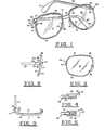
- the construction of the eyeglass frames 14 are rather conventional as illustrated in Figure 1. They utilize a first lens ring 16 retaining a first lens 17 and a second lens ring 18 retaining a lens 19.
- the two lens rings 18 and 19 are secured in an integral structure with a nose bridge 24 and the lens rings 18 and 19 are equipped with a first nose pad 25 and a second nose pad 26 of conventional construction.
- the eyeglass frames 14 include a first temple member 27 and a second temple member 28 having first and second ear loops 30 and 32.
- the temple members 27 and 28 are attached to the eyeglass frames 14 utilizing a conventional construction for a first and a second temple hinge 34 and 36.
- the temple members are secured to the eyeglass frame 14 by means of conventional hinge pins 38.
- the variation in construction of eyeglass frames 14 of this invention resides in the manner in which the first and second lenses 17 and 19 are secured to the first and second lens rings 16 and 18.
- the lenses 17 and 19 are secured to the lens rings 16 and 18 by means of their sliding under and being grasped by inner lens hooks 40 and upper lens hooks 42 as well as lower lens hook 44. These various hooks project outward from the lens rings 16 and 18 and project over the lenses 17 and 19. Engagement is constructed in a relatively loose, slidable, grasping contact.
- the first and second lenses 17 and 19 are locked into a relatively firm position on the lens rings 16 and 18 by means of a movable temple lens latch 46. Two species of this invention with different configurations and constructions of the temple lens latch 46 will be described hereinafter.
- FIGs 1-3 The preferred embodiment of this invention is illustrated in Figures 1-3, which consist of a temple extension 48 into which is formed or machined a latch slot 49.
- the latch arm 50 is tiltably mounted in the latch slot 49 and secured into position by means of a latch pin 51 which, in movement from a vertical position to a horizontal position, moving over a detent (not shown).
- This construction provides a slight restriction to the rotation of latch arm 50 tending to retain the latch arm in the forward projecting position as illustrated in Figure 1. In this configuration the lens is retained in engagement with the various lens hooks 40, 42 and 44.
- the latch arm 50 projects forward as illustrated in Figure 1, the lens cannot be removed from first lens ring 16 nor the second lens ring 18.
- the first and second lenses 17 and 19 may be readily removed from the eyeglass frame 14.
- This readily detachable re- securing feature permits an interchangeability of lenses of varying densities or permits changing from the shaded sunglass type lens to the light amber shooting glass lens.
- the second species of the invention is illustrated in Figures 4, 5, and 6.
- the construction visualized in this embodiment incorporates a latch slide 56 in lieu of the tilting latch arm 50 described in the species above.
- the latch slide 56 as visualized, is illustrated in detail in Figures 4 and 6.
- Latch slide 56 is mounted in a structure somewhat equivalent to temple extension 48.
- Temple extension 48 is constructed with a recess to which is mounted a latch spring 58 which spring loads the latch slide 56 to the extended position.
- a small detent may be provided in the temple extension 48 to retain the latch slide 56 in a desired position.
- the purpose of this invention is to permit a changing of the first and second lenses 17 and 19 as desired by the user.
- Devices of this invention permit the changing, if desired, of the lenses 17 and 19 without removing the eyeglass frame 14 from the wearer.
- the device of this invention is visualized primarily for utilization in sunglasses or shooting glasses wherein various densities of lenses might be utilized, all variations in lenses are possible, such as a shifting from a prescription lens to a non-prescription lens, or the interchangeability of prescription lenses.
- Polarized glass might be utilized or various tints or shade interchangeable.
- the device of this invention in effect, provides a slot into which the lenses 17 and 19 project and they are latched into position by a temple lens latch 46 of various configurations retaining the lenses 17 and 19 in position from the side of the lens rings 16 and 18 adjacent the temple members 27 and 28.
Landscapes
- Physics & Mathematics (AREA)
- Health & Medical Sciences (AREA)
- General Physics & Mathematics (AREA)
- Ophthalmology & Optometry (AREA)
- Optics & Photonics (AREA)
- Eyeglasses (AREA)
Claims (2)
Priority Applications (1)
| Application Number | Priority Date | Filing Date | Title |
|---|---|---|---|
| AT81900599T ATE10978T1 (de) | 1980-02-25 | 1981-01-19 | Brillenfassung mit demontierbaren glaesern. |
Applications Claiming Priority (2)
| Application Number | Priority Date | Filing Date | Title |
|---|---|---|---|
| US06/124,541 US4304469A (en) | 1980-02-25 | 1980-02-25 | Eyeglass frame having removable lenses |
| US124541 | 1998-07-29 |
Publications (3)
| Publication Number | Publication Date |
|---|---|
| EP0046785A1 EP0046785A1 (de) | 1982-03-10 |
| EP0046785A4 EP0046785A4 (de) | 1982-06-18 |
| EP0046785B1 true EP0046785B1 (de) | 1984-12-27 |
Family
ID=22415477
Family Applications (1)
| Application Number | Title | Priority Date | Filing Date |
|---|---|---|---|
| EP81900599A Expired EP0046785B1 (de) | 1980-02-25 | 1981-01-19 | Brillenfassung mit demontierbaren gläsern |
Country Status (5)
| Country | Link |
|---|---|
| US (1) | US4304469A (de) |
| EP (1) | EP0046785B1 (de) |
| JP (1) | JPS6010286B2 (de) |
| CA (1) | CA1144790A (de) |
| WO (1) | WO1981002473A1 (de) |
Cited By (1)
| Publication number | Priority date | Publication date | Assignee | Title |
|---|---|---|---|---|
| US20210373356A1 (en) * | 2020-05-29 | 2021-12-02 | Dartangnan Walker | Modular Eyeglasses |
Families Citing this family (28)
| Publication number | Priority date | Publication date | Assignee | Title |
|---|---|---|---|---|
| DE3612989A1 (de) * | 1986-04-17 | 1987-10-29 | Axel J Smidt | Glasklammerbrille |
| FR2614436B1 (fr) * | 1987-04-21 | 1991-03-15 | Essilor Int | Monture de lunettes a fils souples pour le maintien des verres |
| US4983030A (en) * | 1987-10-08 | 1991-01-08 | Up To Date, Inc. | Retaining mechanism for eyeglasses having interchangeable lenses |
| US5478824A (en) * | 1994-02-17 | 1995-12-26 | Gargoyles, Inc. | Adherent corrective lens |
| US6170952B1 (en) | 1993-12-07 | 2001-01-09 | Neoptx, Inc. | Adherent corrective lenses and eyeglasses embodying the same |
| US5418580A (en) * | 1994-05-05 | 1995-05-23 | Larry L. Sondrol | Interchangeable lens eyeglasses with pivoting temple release mechanism |
| US5579062A (en) * | 1994-05-05 | 1996-11-26 | Sondrol; Larry L. | Interchangeable lens eyeglasses with temple release mechanism |
| GB2295902A (en) * | 1994-12-07 | 1996-06-12 | Chrome Mechanics Ltd | Spectacle frame |
| US5980036A (en) * | 1997-06-30 | 1999-11-09 | World Precision Instruments, Inc. | Eyeglass devices with removable auxiliary lenses or frames |
| US6074059A (en) * | 1998-03-30 | 2000-06-13 | Glass; Theodore A. | Sunglasses with removable lenses |
| US7029115B2 (en) * | 2004-03-19 | 2006-04-18 | Michael Toulch | Rimless eyeglasses |
| EP1688452B1 (de) * | 2005-02-04 | 2008-02-06 | E.I. du Pont de Nemours and Company | Zusammensetzungen Fluorkohlenstoff-gepfropfte Polysiloxane aufweisend |
| JP5676439B2 (ja) | 2008-07-03 | 2015-02-25 | オークリー インコーポレイテッド | 浮遊レンズ取り付けシステム |
| US8469510B2 (en) | 2009-01-09 | 2013-06-25 | Oakley, Inc. | Eyewear with enhanced ballistic resistance |
| SG184119A1 (en) | 2010-03-19 | 2012-10-30 | Oakley Inc | Eyewear |
| WO2012021863A1 (en) | 2010-08-13 | 2012-02-16 | Oakley, Inc. | Eyewear with lens retention mechanism |
| JP5934798B2 (ja) | 2011-09-22 | 2016-06-15 | オークリー インコーポレイテッド | アイウェアのための取り付けメカニズム |
| US9122078B2 (en) | 2011-12-01 | 2015-09-01 | Oakley, Inc. | Releasable earstem mounting mechanism for eyewear |
| JP5942467B2 (ja) * | 2012-02-22 | 2016-06-29 | ソニー株式会社 | 表示装置 |
| WO2014036274A2 (en) | 2012-08-31 | 2014-03-06 | Oakley, Inc. | Eyewear having multiple ventilation states |
| GB2522389B (en) | 2012-12-11 | 2019-07-31 | Oakley Inc | Eyewear with outriggers |
| USD723097S1 (en) | 2013-02-28 | 2015-02-24 | Kevin Alexander Maurer | Eyeglass frame with angled proximal and distal temples |
| WO2014138159A1 (en) | 2013-03-07 | 2014-09-12 | Oakley, Inc. | Regeneratable ant-fogging element for goggle |
| AU2015235947B2 (en) | 2014-03-27 | 2017-12-07 | Oakley, Inc. | Mounting mechanism for eyewear |
| WO2017062813A1 (en) | 2015-10-09 | 2017-04-13 | Oakley, Inc. | Headworn supports with passive venting and removable lens |
| US9709817B2 (en) | 2015-12-07 | 2017-07-18 | Oakley, Inc. | Eyewear retention devices and methods |
| EP3387485B1 (de) | 2015-12-08 | 2025-05-07 | Oakley, Inc. | Vorrichtungen und verfahren zum ziehen von brillen |
| US10359642B2 (en) | 2016-04-22 | 2019-07-23 | Oakley, Inc. | Mounting mechanism for eyewear |
Family Cites Families (10)
| Publication number | Priority date | Publication date | Assignee | Title |
|---|---|---|---|---|
| US1308477A (en) * | 1919-07-01 | William m | ||
| US1614827A (en) * | 1925-06-11 | 1927-01-18 | John A Coats | Auxiliary lens for eyeglasses |
| US2452159A (en) * | 1945-05-28 | 1948-10-26 | Giltner S Small | Spectacles with readily removable lenses |
| US2652746A (en) * | 1950-12-11 | 1953-09-22 | Shanks Robert Randolph | Eyeglasses frame with detachably mounted lenses |
| FR1055825A (fr) * | 1951-02-20 | 1954-02-22 | Perfectionnement aux montures de lunettes optiques, solaires et faces supplémentaires solaires | |
| US2738709A (en) * | 1951-09-08 | 1956-03-20 | Rose C Matthews | Interchangeable eyeglass frame |
| GB750926A (en) * | 1953-10-29 | 1956-06-20 | Francis Owen Wheway | Spectacle frames |
| FR1190806A (fr) * | 1958-01-23 | 1959-10-15 | Lunettes perfectionnées à verres interchangeables | |
| US3427098A (en) * | 1966-06-13 | 1969-02-11 | Donald L Johnston | Sunshade attachment for eyeglasses |
| DE7717685U1 (de) * | 1977-06-03 | 1977-10-13 | Carrera Herstellung Und Vertrieb Von Sportbrillen Und Sportartikeln Gmbh, 8013 Haar | Schutzbrille, insbesondere sonnenschutzbrille mit metallfassung |
-
1980
- 1980-02-25 US US06/124,541 patent/US4304469A/en not_active Expired - Lifetime
-
1981
- 1981-01-19 JP JP56500910A patent/JPS6010286B2/ja not_active Expired
- 1981-01-19 WO PCT/US1981/000095 patent/WO1981002473A1/en not_active Ceased
- 1981-01-19 EP EP81900599A patent/EP0046785B1/de not_active Expired
- 1981-01-20 CA CA000368915A patent/CA1144790A/en not_active Expired
Cited By (1)
| Publication number | Priority date | Publication date | Assignee | Title |
|---|---|---|---|---|
| US20210373356A1 (en) * | 2020-05-29 | 2021-12-02 | Dartangnan Walker | Modular Eyeglasses |
Also Published As
| Publication number | Publication date |
|---|---|
| JPS57500127A (de) | 1982-01-21 |
| CA1144790A (en) | 1983-04-19 |
| JPS6010286B2 (ja) | 1985-03-16 |
| EP0046785A1 (de) | 1982-03-10 |
| WO1981002473A1 (en) | 1981-09-03 |
| US4304469A (en) | 1981-12-08 |
| EP0046785A4 (de) | 1982-06-18 |
Similar Documents
| Publication | Publication Date | Title |
|---|---|---|
| US4304469A (en) | Eyeglass frame having removable lenses | |
| US4102566A (en) | Rimless spectacle | |
| EP3058420B1 (de) | Modulare brillen mit austauschbaren bügeln und vorderteilen | |
| US6491390B1 (en) | Clip-on glasses | |
| US9400401B2 (en) | Modular interchangeable facades for eyewear | |
| US4405213A (en) | Makeup eyeglasses with sliding frames | |
| EP2592463B1 (de) | Linsenaufnahmearretierung für Brille | |
| US9256080B2 (en) | Receptor and lock for glasses with removable lenses | |
| US2607919A (en) | Eyeshield | |
| US4357080A (en) | Eyeglass frame having removable lens | |
| US3958867A (en) | Eyeglass structure | |
| JP2024520174A (ja) | 眼鏡のサイドシールド | |
| KR102498754B1 (ko) | 안경다리의 각도 조절이 가능하고 안경다리의 탈부착이 가능한 아이웨어 | |
| US2452159A (en) | Spectacles with readily removable lenses | |
| WO1999064918A1 (en) | Eyewear with replaceable lens system | |
| US2825267A (en) | Ophthalmic mountings | |
| US4666266A (en) | Eyeglasses having lens storage means | |
| KR102430228B1 (ko) | 보조렌즈 착탈형 안경 | |
| KR20220002437U (ko) | 렌즈 교환이 가능한 단일 렌즈 안경 | |
| KR101947331B1 (ko) | 렌즈 교체가 가능한 스포츠용 고글 | |
| US2748655A (en) | Spectacle frames | |
| JP2002006265A (ja) | 眼 鏡 | |
| US6974213B1 (en) | Monoblock assembly for eyewear | |
| JPH05507565A (ja) | コンビネーション眼鏡 | |
| KR200335224Y1 (ko) | 안경알 탈부착식 안경 |
Legal Events
| Date | Code | Title | Description |
|---|---|---|---|
| PUAI | Public reference made under article 153(3) epc to a published international application that has entered the european phase |
Free format text: ORIGINAL CODE: 0009012 |
|
| 17P | Request for examination filed |
Effective date: 19811029 |
|
| AK | Designated contracting states |
Designated state(s): AT DE FR GB |
|
| RBV | Designated contracting states (corrected) |
Designated state(s): AT DE FR GB |
|
| GRAA | (expected) grant |
Free format text: ORIGINAL CODE: 0009210 |
|
| AK | Designated contracting states |
Designated state(s): AT DE FR GB |
|
| REF | Corresponds to: |
Ref document number: 10978 Country of ref document: AT Date of ref document: 19850115 Kind code of ref document: T |
|
| REF | Corresponds to: |
Ref document number: 3167883 Country of ref document: DE Date of ref document: 19850207 |
|
| ET | Fr: translation filed | ||
| PLBE | No opposition filed within time limit |
Free format text: ORIGINAL CODE: 0009261 |
|
| 26N | No opposition filed | ||
| PGFP | Annual fee paid to national office [announced via postgrant information from national office to epo] |
Ref country code: AT Payment date: 19890111 Year of fee payment: 9 |
|
| PGFP | Annual fee paid to national office [announced via postgrant information from national office to epo] |
Ref country code: FR Payment date: 19890112 Year of fee payment: 9 |
|
| PGFP | Annual fee paid to national office [announced via postgrant information from national office to epo] |
Ref country code: GB Payment date: 19890131 Year of fee payment: 9 |
|
| PGFP | Annual fee paid to national office [announced via postgrant information from national office to epo] |
Ref country code: DE Payment date: 19890228 Year of fee payment: 9 |
|
| PG25 | Lapsed in a contracting state [announced via postgrant information from national office to epo] |
Ref country code: GB Effective date: 19900119 Ref country code: AT Effective date: 19900119 |
|
| GBPC | Gb: european patent ceased through non-payment of renewal fee | ||
| PG25 | Lapsed in a contracting state [announced via postgrant information from national office to epo] |
Ref country code: FR Effective date: 19900928 |
|
| PG25 | Lapsed in a contracting state [announced via postgrant information from national office to epo] |
Ref country code: DE Effective date: 19901002 |
|
| REG | Reference to a national code |
Ref country code: FR Ref legal event code: ST |