EP0046866A2 - Joint à lèvres - Google Patents
Joint à lèvres Download PDFInfo
- Publication number
- EP0046866A2 EP0046866A2 EP81105623A EP81105623A EP0046866A2 EP 0046866 A2 EP0046866 A2 EP 0046866A2 EP 81105623 A EP81105623 A EP 81105623A EP 81105623 A EP81105623 A EP 81105623A EP 0046866 A2 EP0046866 A2 EP 0046866A2
- Authority
- EP
- European Patent Office
- Prior art keywords
- lip
- sealing
- lip seal
- protective
- machine part
- Prior art date
- Legal status (The legal status is an assumption and is not a legal conclusion. Google has not performed a legal analysis and makes no representation as to the accuracy of the status listed.)
- Granted
Links
- 238000007789 sealing Methods 0.000 claims abstract description 55
- 230000001681 protective effect Effects 0.000 claims abstract description 32
- 239000007788 liquid Substances 0.000 claims abstract description 14
- 239000013013 elastic material Substances 0.000 claims abstract description 4
- 239000003792 electrolyte Substances 0.000 claims description 14
- 229910052751 metal Inorganic materials 0.000 claims description 7
- 239000002184 metal Substances 0.000 claims description 7
- 230000000694 effects Effects 0.000 abstract description 8
- 229910052782 aluminium Inorganic materials 0.000 description 8
- XAGFODPZIPBFFR-UHFFFAOYSA-N aluminium Chemical compound [Al] XAGFODPZIPBFFR-UHFFFAOYSA-N 0.000 description 8
- 230000007797 corrosion Effects 0.000 description 4
- 238000005260 corrosion Methods 0.000 description 4
- 210000001520 comb Anatomy 0.000 description 2
- 239000007772 electrode material Substances 0.000 description 2
- 230000007704 transition Effects 0.000 description 2
- KWYUFKZDYYNOTN-UHFFFAOYSA-M Potassium hydroxide Chemical compound [OH-].[K+] KWYUFKZDYYNOTN-UHFFFAOYSA-M 0.000 description 1
- 238000009825 accumulation Methods 0.000 description 1
- 238000005452 bending Methods 0.000 description 1
- 238000010276 construction Methods 0.000 description 1
- 230000007547 defect Effects 0.000 description 1
- 239000012535 impurity Substances 0.000 description 1
- 230000007774 longterm Effects 0.000 description 1
- 239000000463 material Substances 0.000 description 1
- 230000036316 preload Effects 0.000 description 1
- 238000004080 punching Methods 0.000 description 1
- 229920006395 saturated elastomer Polymers 0.000 description 1
- 239000000565 sealant Substances 0.000 description 1
Images

Classifications
-
- F—MECHANICAL ENGINEERING; LIGHTING; HEATING; WEAPONS; BLASTING
- F16—ENGINEERING ELEMENTS AND UNITS; GENERAL MEASURES FOR PRODUCING AND MAINTAINING EFFECTIVE FUNCTIONING OF MACHINES OR INSTALLATIONS; THERMAL INSULATION IN GENERAL
- F16J—PISTONS; CYLINDERS; SEALINGS
- F16J15/00—Sealings
- F16J15/16—Sealings between relatively-moving surfaces
- F16J15/32—Sealings between relatively-moving surfaces with elastic sealings, e.g. O-rings
- F16J15/3204—Sealings between relatively-moving surfaces with elastic sealings, e.g. O-rings with at least one lip
- F16J15/3232—Sealings between relatively-moving surfaces with elastic sealings, e.g. O-rings with at least one lip having two or more lips
-
- F—MECHANICAL ENGINEERING; LIGHTING; HEATING; WEAPONS; BLASTING
- F16—ENGINEERING ELEMENTS AND UNITS; GENERAL MEASURES FOR PRODUCING AND MAINTAINING EFFECTIVE FUNCTIONING OF MACHINES OR INSTALLATIONS; THERMAL INSULATION IN GENERAL
- F16J—PISTONS; CYLINDERS; SEALINGS
- F16J15/00—Sealings
- F16J15/16—Sealings between relatively-moving surfaces
- F16J15/168—Sealings between relatively-moving surfaces which permits material to be continuously conveyed
-
- F—MECHANICAL ENGINEERING; LIGHTING; HEATING; WEAPONS; BLASTING
- F16—ENGINEERING ELEMENTS AND UNITS; GENERAL MEASURES FOR PRODUCING AND MAINTAINING EFFECTIVE FUNCTIONING OF MACHINES OR INSTALLATIONS; THERMAL INSULATION IN GENERAL
- F16J—PISTONS; CYLINDERS; SEALINGS
- F16J15/00—Sealings
- F16J15/16—Sealings between relatively-moving surfaces
- F16J15/32—Sealings between relatively-moving surfaces with elastic sealings, e.g. O-rings
- F16J15/3204—Sealings between relatively-moving surfaces with elastic sealings, e.g. O-rings with at least one lip
- F16J15/3228—Sealings between relatively-moving surfaces with elastic sealings, e.g. O-rings with at least one lip formed by deforming a flat ring
-
- H—ELECTRICITY
- H01—ELECTRIC ELEMENTS
- H01M—PROCESSES OR MEANS, e.g. BATTERIES, FOR THE DIRECT CONVERSION OF CHEMICAL ENERGY INTO ELECTRICAL ENERGY
- H01M12/00—Hybrid cells; Manufacture thereof
- H01M12/02—Details
Definitions
- the invention relates to a lip seal made of rubber-elastic material with at least one sealing lip having a cutting-like sealing comb, in particular for sealing an axially movable machine part against a liquid space.
- a galvanic metal-air cell This consists of a consumable metal electrode and an air electrode, the distance of which is kept constant during operation by tracking the metal electrode.
- the consumable metal electrode protrudes into the liquid space in such a sealed manner that its end face is the sole working surface.
- an elastic lip seal that has a conical inner surface to form a sharp sealing edge towards the electrolyte space, which tightly encloses the consumable electrode like a lip (DE-PS 26 07 519).
- the desired sealing of the liquid space in continuous operation with the known seal is not guaranteed.
- the electrolyte movement and local high reaction temperatures lead to corrosion in the sealing area such that the liquid can infiltrate the seal. This behavior is promoted by impurities in the electrode material, which can lead to pitting or defects.
- Another influencing factor is the surface quality of the metal electrode. In order to obtain a perfect seal, it is necessary to polish the surface, whereby even the original turning grooves reappear under the influence of the electrolyte after a certain time. Overall, therefore, a satisfactory service life of the galvanic cell could not be achieved regularly, since the leaks that occur cause damage to the electrolyte, which leads to cell failure.
- the invention has for its object to provide an improved lip seal generally for sealing an axially movable machine part against a liquid space, but preferably for a galvanic cell of the type described above, the sealing effect is guaranteed long term.
- the disadvantages described should be avoided.
- a membrane-like protective lip is formed on the liquid side in front of the sealing comb, which rests flat on the machine part to be sealed.
- the protective lip is advantageously formed in one piece with the lip seal and, due to its inherent tension or pretension, adapts to the upper with high surface pressure surface of the machine part to be sealed.
- the excellent results achieved with this seal - so far no failure of a galvanic cell over the entire life of the consumable electrode - are based on the fact that the protective lip does not allow the essential effects of corrosion to take effect. For example, the effect of the electrolyte movement on the sealing area is almost completely eliminated.
- the rate of corrosion itself by the electrolyte is significantly reduced by the fact that an extraordinarily thin layer of electrolyte forms below the protective lip, which is quickly saturated with the consumable metal and thus loses its aggressiveness.
- the pretensioning of the protective lip can be structurally adjusted to a greater or lesser extent by providing an undercut which influences the elasticity at the transition from the sealing comb to the protective lip. Another possibility of influence is given by the choice of the direction of extension of the protective lip in the unloaded state. The greater the angle of the protective lip in the unloaded state compared to its direction of extension in the installed state, the stronger the preload. In the preferred embodiment it is proposed to provide an undercut and to form the direction of extension parallel to that of the sealing lip in the unloaded state.
- the protective lip becomes wedge-shaped on the outside and has a projecting length of between 1/5 and 1/20 of the diameter of the machine part.
- this further improves the sealing effect achieved that a multiple seal is provided one behind the other by the lip seal is designed as a roof-shaped cross-section double lip seal with protective lip.
- the essential advantage is achieved that it is also possible to work with impure electrode materials, for example aluminum of 98% purity, and that the surface is not polished. This is a major economic advantage.
- the lip seals according to the invention are normally ring-shaped. However, other shapes are also conceivable, but care must be taken to ensure that the same radial pressure forces are adjusted by the shape to match the surfaces to be sealed.
- the ring flange of the lip seal provided for fastening in the housing is designed as an outer multiple seal with a plurality of sealing combs arranged one behind the other.
- EPTM int. Designation
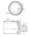
- the lip seal 1 is made of rubber-elastic material, which is shaped to a substantially roof-shaped cross section such that two sealing lips 2, 3 with cutting-like sealing combs 4, 5 and on the opposite side in a collar 6 for positioning in a housing, not shown.
- a membrane-like protective lip 7 is formed in one piece with the lip seal 1.
- the transition from the sealing comb 4 to the protective lip 7 is carried out with an undercut 8, which facilitates an elastic bending of the protective lip 7 from the direction of extension shown by 90 ° to the outside with the build-up of a pretension.
- the protective lip tapers forward and wedge-shaped has a projecting length of 1/10 of the inner diameter of the lip seal in the illustrated embodiment.
- the dash-dotted vertical lines indicate that, depending on the application, a shorter projection may also be appropriate.
- the protective lip can be reduced accordingly by simply punching out.
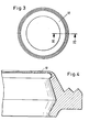
- the modified embodiment of a lip seal shown in FIGS. 3 and 4 is basically identical in construction, with the exception of the sealing edges on the housing and the selected dimensions. With this lip seal, the protective lip projects by 1/5 of the inside diameter of the lip seal, so that the area covered in the installed state is enlarged.
- FIG. 5 of the drawing A lip seal installed in a metal-air cell is shown in FIG. 5 of the drawing.
- the metal-air cell essentially consists of a cylindrically shaped consumable aluminum electrode 13, the end face 14 of which is the sole working surface, as well as an air electrode 15 arranged at a distance therefrom and an electrolyte space 16 arranged in between.
- the aluminum electrode 13 can be pushed in a housing 17 is mounted, in the wall of which a lip seal 18 of the type described with reference to FIGS. 1 to 4 is inserted.
- the extracted detail drawing shows that the lip seal 18 has a protective lip 19, which lies close to the surface of the aluminum electrode 13, leaving a very flat saturation space 20.
- the undercut of the lip seal merges into a first sealing comb 21, which is followed by a second saturation chamber 22 and the second sealing comb 23.
- the protective lip 19 prevents any attack due to the electrolyte movement due to its tight contact with voltage on the surface of the aluminum electrode.
- the protective lip adapts to the respective shape of the surface. Despite these protective effects, easy tracking of the aluminum electrode 13 is ensured. It is pointed out that this problem could not be solved, for example when using a stuffing box as a seal.
- the metal-air cell shown worked until the aluminum electrode, which had a diameter of approximately 80 mm and a length of approximately 200 mm, was completely consumed without loss of the sealing effect.
Landscapes
- Engineering & Computer Science (AREA)
- General Engineering & Computer Science (AREA)
- Mechanical Engineering (AREA)
- Manufacturing & Machinery (AREA)
- Chemical & Material Sciences (AREA)
- Chemical Kinetics & Catalysis (AREA)
- Electrochemistry (AREA)
- General Chemical & Material Sciences (AREA)
- Sealing Battery Cases Or Jackets (AREA)
- Hybrid Cells (AREA)
- Sealing With Elastic Sealing Lips (AREA)
- Gasket Seals (AREA)
Applications Claiming Priority (2)
| Application Number | Priority Date | Filing Date | Title |
|---|---|---|---|
| DE3032445 | 1980-08-28 | ||
| DE19803032445 DE3032445A1 (de) | 1980-08-28 | 1980-08-28 | Lippendichtung |
Publications (3)
| Publication Number | Publication Date |
|---|---|
| EP0046866A2 true EP0046866A2 (fr) | 1982-03-10 |
| EP0046866A3 EP0046866A3 (en) | 1982-03-31 |
| EP0046866B1 EP0046866B1 (fr) | 1984-10-17 |
Family
ID=6110604
Family Applications (1)
| Application Number | Title | Priority Date | Filing Date |
|---|---|---|---|
| EP81105623A Expired EP0046866B1 (fr) | 1980-08-28 | 1981-07-17 | Joint à lèvres |
Country Status (4)
| Country | Link |
|---|---|
| US (1) | US4421322A (fr) |
| EP (1) | EP0046866B1 (fr) |
| JP (1) | JPS5761863A (fr) |
| DE (1) | DE3032445A1 (fr) |
Families Citing this family (6)
| Publication number | Priority date | Publication date | Assignee | Title |
|---|---|---|---|---|
| US5187007A (en) * | 1985-12-27 | 1993-02-16 | Lintec Corporation | Adhesive sheets |
| US5624123A (en) * | 1994-05-11 | 1997-04-29 | Tuf-Tite, Inc. | Pipe seal assembly for poured concrete on-site waste disposal system components |
| US5711536A (en) * | 1994-05-11 | 1998-01-27 | Tuf-Tite, Inc. | Seal component for use in on-site poured concrete or plastic tank or box components of fluid distribution systems |
| DE19505012A1 (de) * | 1995-02-15 | 1996-08-22 | Teves Gmbh Alfred | Dichtmanschette für hydraulische Anlagen |
| US7134671B2 (en) * | 2002-12-20 | 2006-11-14 | Macrotech Polyseal, Inc. | Lip seal having increased contact force at interface and apparatus incorporating the same |
| JP5327703B2 (ja) * | 2009-01-16 | 2013-10-30 | Nok株式会社 | ロールバックシール |
Family Cites Families (20)
| Publication number | Priority date | Publication date | Assignee | Title |
|---|---|---|---|---|
| US2561884A (en) * | 1946-06-19 | 1951-07-24 | Warren C Perrow | Pipe joint |
| US2487669A (en) * | 1946-12-16 | 1949-11-08 | Milton D Pattullo | Journal box seal |
| US2558183A (en) * | 1947-04-07 | 1951-06-26 | Victor Mfg & Gasket Co | Split seal |
| DE922317C (de) | 1953-06-23 | 1955-01-13 | Bosch Gmbh Robert | Dichtung, insbesondere fuer Scheibenkolben |
| US2897533A (en) * | 1956-02-16 | 1959-08-04 | Gen Motors Corp | Grommets, bushings and the like |
| US3379444A (en) * | 1961-01-09 | 1968-04-23 | Borg Warner | Fluid seal structure |
| DE1240347B (de) * | 1963-03-29 | 1967-05-11 | Westland Gummiwerke G M B H & | Abdichtung fuer Muffenrohrverbindungen |
| FR1432209A (fr) | 1965-04-30 | 1966-03-18 | Fribaud Et Cie Soc Ets | Pièce de raccordement pour cuvette de water-closet |
| CH469692A (de) * | 1966-07-08 | 1969-03-15 | Ciba Geigy | Verfahren zur Herstellung von Glycidylestern von Carbonsäuren mit hohem Epoxydsauerstoffgehalt |
| US3480286A (en) * | 1967-08-09 | 1969-11-25 | Victor Mfg & Gasket Co | Valve stem seal |
| US3430989A (en) * | 1967-12-20 | 1969-03-04 | Pacific Clay Products | Pipe coupling |
| DE1981067U (de) * | 1968-01-05 | 1968-03-14 | Goetzewerke | Radlagerdichtung. |
| GB1262074A (en) * | 1968-04-30 | 1972-02-02 | Morganite Carbon Ltd | Liquid-tight sealing device for relatively rotatable parts |
| IT979768B (it) * | 1972-05-05 | 1974-09-30 | Glaenzer Spicer Sa | Dispositivo di protezione per giunti cardanici scorrevoli contro polveri e corpi estranei |
| GB1436310A (en) * | 1972-08-11 | 1976-05-19 | British Steel Corp | Pipe joints and sealing members therefor |
| AU500848B2 (en) * | 1976-02-25 | 1979-05-31 | Accumulatorenwekk Hoppecke Carl Zoellner & Sohn | Electrochemical battery |
| DE2706016C3 (de) * | 1977-02-12 | 1981-03-19 | Accumulatorenwerk Hoppecke Carl Zoellner & Sohn, 5000 Köln | Elektrochemische Batterie |
| US4155560A (en) * | 1977-11-23 | 1979-05-22 | Garlock Inc. | Water pump seal and method |
| JPS5592961U (fr) * | 1978-12-20 | 1980-06-27 | ||
| US4311317A (en) * | 1979-08-20 | 1982-01-19 | Bartels Harold U | Lip and radial seal |
-
1980
- 1980-08-28 DE DE19803032445 patent/DE3032445A1/de active Granted
-
1981
- 1981-07-17 EP EP81105623A patent/EP0046866B1/fr not_active Expired
- 1981-08-12 JP JP56125415A patent/JPS5761863A/ja active Granted
- 1981-08-20 US US06/294,697 patent/US4421322A/en not_active Expired - Fee Related
Also Published As
| Publication number | Publication date |
|---|---|
| DE3032445C2 (fr) | 1988-09-29 |
| EP0046866B1 (fr) | 1984-10-17 |
| JPS6349854B2 (fr) | 1988-10-06 |
| EP0046866A3 (en) | 1982-03-31 |
| JPS5761863A (en) | 1982-04-14 |
| US4421322A (en) | 1983-12-20 |
| DE3032445A1 (de) | 1982-04-01 |
Similar Documents
| Publication | Publication Date | Title |
|---|---|---|
| EP0235568B1 (fr) | Dispositif de joint racleur à deux lèvres | |
| EP0174427B1 (fr) | Couteau pour séparer la couche de colle d'une vitre collée | |
| EP1552162B1 (fr) | Accumulateur hydraulique | |
| DE3602500A1 (de) | Radial-oeldichtung | |
| DE69802062T2 (de) | Elektrodenkörper/Elektrodenhalter Einheit für Plasmabrenner | |
| EP1348930B1 (fr) | Bande d'étanchéité pour projectile | |
| DE2730981C2 (de) | Behälter für einen Alkalimetall-Schwefel-Akkumulator | |
| EP0046866B1 (fr) | Joint à lèvres | |
| DE69627674T2 (de) | Bürstendichtung mit einer biegsamen frontscheibe | |
| EP0328737B1 (fr) | Joint d'étanchéité | |
| DE1602795A1 (de) | Schneidkoerper und zugehoeriges Klemmwerkzeug | |
| DE102010011095A1 (de) | Düse zum Auftragen flüssiger Materialien | |
| EP0208839A2 (fr) | Coussinet | |
| DE3937896A1 (de) | Verbundelement, insbesondere nutring-dichtung | |
| EP0152938A2 (fr) | Joint d'étanchéité pour piston ou tige de piston | |
| DE19936462B4 (de) | Abstreifring | |
| DE2451348B2 (de) | Innendichtung fuer eine kreiskolben-brennkraftmaschine | |
| DE2628625C3 (de) | Führungselement für das Schußfadeneintragsorgan von Webmaschinen | |
| DE2435089B2 (de) | Dichtungsring aus elastisch verformbarem Material für Muffen-Rohrverbindungen | |
| DE2815021C2 (de) | Kipplager für schwere Bauwerke | |
| EP0100040A2 (fr) | Porte de four à coke à lame d'étanchéité lamellée | |
| EP0861999B1 (fr) | Anneau d'étanchéité | |
| DE3145494A1 (de) | Einrichtung zur fuehrung des kolbens eines arbeitszylinders | |
| DE740498C (de) | Dichtung fuer Lager mit zwei ineinanderliegenden Lagerringen | |
| DE2755512C3 (de) | Zur Verwendung in einer elektrochemischen Vorrichtung bestimmter Bauteil |
Legal Events
| Date | Code | Title | Description |
|---|---|---|---|
| PUAI | Public reference made under article 153(3) epc to a published international application that has entered the european phase |
Free format text: ORIGINAL CODE: 0009012 |
|
| PUAL | Search report despatched |
Free format text: ORIGINAL CODE: 0009013 |
|
| AK | Designated contracting states |
Designated state(s): BE FR GB IT LU NL SE |
|
| AK | Designated contracting states |
Designated state(s): BE FR GB IT LU NL SE |
|
| 17P | Request for examination filed |
Effective date: 19820805 |
|
| ITF | It: translation for a ep patent filed | ||
| GRAA | (expected) grant |
Free format text: ORIGINAL CODE: 0009210 |
|
| AK | Designated contracting states |
Designated state(s): BE FR GB IT LU NL SE |
|
| ET | Fr: translation filed | ||
| PG25 | Lapsed in a contracting state [announced via postgrant information from national office to epo] |
Ref country code: LU Free format text: LAPSE BECAUSE OF NON-PAYMENT OF DUE FEES Effective date: 19850731 |
|
| PLBE | No opposition filed within time limit |
Free format text: ORIGINAL CODE: 0009261 |
|
| STAA | Information on the status of an ep patent application or granted ep patent |
Free format text: STATUS: NO OPPOSITION FILED WITHIN TIME LIMIT |
|
| 26N | No opposition filed | ||
| PGFP | Annual fee paid to national office [announced via postgrant information from national office to epo] |
Ref country code: NL Payment date: 19870731 Year of fee payment: 7 |
|
| PG25 | Lapsed in a contracting state [announced via postgrant information from national office to epo] |
Ref country code: SE Effective date: 19880718 |
|
| PG25 | Lapsed in a contracting state [announced via postgrant information from national office to epo] |
Ref country code: BE Effective date: 19890731 |
|
| BERE | Be: lapsed |
Owner name: ACCUMULATORENWERKE HOPPECKE CARL ZOELLNER & SOHN Effective date: 19890731 |
|
| PG25 | Lapsed in a contracting state [announced via postgrant information from national office to epo] |
Ref country code: NL Effective date: 19900201 |
|
| NLV4 | Nl: lapsed or anulled due to non-payment of the annual fee | ||
| ITTA | It: last paid annual fee | ||
| PGFP | Annual fee paid to national office [announced via postgrant information from national office to epo] |
Ref country code: GB Payment date: 19920616 Year of fee payment: 12 |
|
| PGFP | Annual fee paid to national office [announced via postgrant information from national office to epo] |
Ref country code: FR Payment date: 19920716 Year of fee payment: 12 |
|
| PG25 | Lapsed in a contracting state [announced via postgrant information from national office to epo] |
Ref country code: GB Effective date: 19930717 |
|
| GBPC | Gb: european patent ceased through non-payment of renewal fee |
Effective date: 19930717 |
|
| PG25 | Lapsed in a contracting state [announced via postgrant information from national office to epo] |
Ref country code: FR Effective date: 19940331 |
|
| REG | Reference to a national code |
Ref country code: FR Ref legal event code: ST |
|
| EUG | Se: european patent has lapsed |
Ref document number: 81105623.3 Effective date: 19890510 |