EP0046872A2 - Moteur à combustion à piston à turbo-compresseur à gaz d'échappement - Google Patents
Moteur à combustion à piston à turbo-compresseur à gaz d'échappement Download PDFInfo
- Publication number
- EP0046872A2 EP0046872A2 EP81105779A EP81105779A EP0046872A2 EP 0046872 A2 EP0046872 A2 EP 0046872A2 EP 81105779 A EP81105779 A EP 81105779A EP 81105779 A EP81105779 A EP 81105779A EP 0046872 A2 EP0046872 A2 EP 0046872A2
- Authority
- EP
- European Patent Office
- Prior art keywords
- throttle valve
- internal combustion
- combustion engine
- valve
- exhaust gas
- Prior art date
- Legal status (The legal status is an assumption and is not a legal conclusion. Google has not performed a legal analysis and makes no representation as to the accuracy of the status listed.)
- Granted
Links
Images


Classifications
-
- F—MECHANICAL ENGINEERING; LIGHTING; HEATING; WEAPONS; BLASTING
- F02—COMBUSTION ENGINES; HOT-GAS OR COMBUSTION-PRODUCT ENGINE PLANTS
- F02D—CONTROLLING COMBUSTION ENGINES
- F02D41/00—Electrical control of supply of combustible mixture or its constituents
- F02D41/0002—Controlling intake air
- F02D41/0007—Controlling intake air for control of turbo-charged or super-charged engines
-
- F—MECHANICAL ENGINEERING; LIGHTING; HEATING; WEAPONS; BLASTING
- F02—COMBUSTION ENGINES; HOT-GAS OR COMBUSTION-PRODUCT ENGINE PLANTS
- F02B—INTERNAL-COMBUSTION PISTON ENGINES; COMBUSTION ENGINES IN GENERAL
- F02B37/00—Engines characterised by provision of pumps driven at least for part of the time by exhaust
- F02B37/12—Control of the pumps
- F02B37/18—Control of the pumps by bypassing exhaust from the inlet to the outlet of turbine or to the atmosphere
-
- Y—GENERAL TAGGING OF NEW TECHNOLOGICAL DEVELOPMENTS; GENERAL TAGGING OF CROSS-SECTIONAL TECHNOLOGIES SPANNING OVER SEVERAL SECTIONS OF THE IPC; TECHNICAL SUBJECTS COVERED BY FORMER USPC CROSS-REFERENCE ART COLLECTIONS [XRACs] AND DIGESTS
- Y02—TECHNOLOGIES OR APPLICATIONS FOR MITIGATION OR ADAPTATION AGAINST CLIMATE CHANGE
- Y02T—CLIMATE CHANGE MITIGATION TECHNOLOGIES RELATED TO TRANSPORTATION
- Y02T10/00—Road transport of goods or passengers
- Y02T10/10—Internal combustion engine [ICE] based vehicles
- Y02T10/12—Improving ICE efficiencies
Definitions
- the invention relates to a piston internal combustion engine with an exhaust gas turbocharger according to the preamble of the main claim.
- Exhaust gas turbochargers have recently been increasingly used on internal combustion engines for passenger cars in order to increase their performance without having to increase the displacement of the internal combustion engine.
- the blow-off valve is opened at a negative pressure in the intake manifold downstream of the throttle valve, as occurs, for example, in pushing operation or when the throttle valve is suddenly closed, so that part of the exhaust gases are directed past the exhaust gas turbine becomes.
- the boost pressure drops upstream of the throttle valve, which in turn causes the pressure downstream of the throttle valve to drop even further and the internal combustion engine responds quickly to the closing of the throttle valve and reduces its speed.
- the blow-off valve opens at an impermissibly high pressure in the intake manifold downstream of the throttle valve in order to avoid knocking combustion and consequent damage to the internal combustion engine.
- a peculiarity of the known and other conventional controls of the blow-off valve is that in certain load areas of the map of the internal combustion engine there are significant disadvantages in that the exhaust gas throughput of the turbocharger promotes an excessive air volume. This leads to a high pressure upstream of the throttle valve or to a comparatively large pressure drop across the throttle valve. This pressure drop causes loss of work and increases the specific> fuel consumption of the internal combustion engine.
- the invention has for its object to provide a piston internal combustion engine with exhaust gas turbocharger provided with a throttle valve for power control, which has a favorable specific consumption in the entire map.
- the lower temperatures and the lower exhaust gas back pressure reduce the tendency to knock and thus allow earlier ignition angles, which in conjunction with dethrottling leads to an improvement in efficiency.
- the claim 2 characterizes a particularly useful design of the piston internal combustion engine, in which the target values of the pressure difference across the throttle valve are determined by the respective speed and the position of the throttle valve.
- a further parameter is used in the determination of the target values.
- the invention can be used for all types of internal combustion engines in which a throttle valve is arranged between the charging stage of the exhaust gas turbocharger and the internal combustion engine.
- the invention is particularly well suited for spark-ignited (piston internal combustion engines with conventional power control by means of a throttle valve).
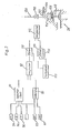
- an internal combustion engine 6 has a plurality of cylinders 8, in which pistons, not shown, work.
- Each cylinder 8 is connected via a suction line 10 to a suction pipe 12 (drawn continuously) and via an outlet line 14 to an exhaust manifold 16.
- An exhaust gas turbocharger designated as a whole by 18, is connected to the exhaust gas number 16 and has an exhaust gas turbine 20 and a charging turbine 22 on a common shaft.
- An exhaust pipe 24 leads from the exhaust gas turbine 20 to a muffler 26 of the exhaust of the internal combustion engine.
- the outlet of the charging turbine 22 is connected to the suction pipe 12.
- a throttle valve 30, which interacts with an accelerator pedal 28, sits in the inlet to the intake manifold 12.
- An air flow measuring device 34 is arranged at the inlet or charging turbine 22 and measures the throughput of the fresh air drawn in by the charging turbine 22 through an air filter 36.
- the air flow measuring device 34 works together with an injection system, by means of which an amount of fuel corresponding to the air flow rate is injected into each suction line 10.
- a blow-off valve 38 is connected to the exhaust manifold 16 via a connecting line 37, through which the exhaust gases of the internal combustion engine 6 can escape directly into the exhaust pipe 24 bypassing the exhaust gas turbine 20.
- This blow-off valve 38 has a closure member 40 with a shaft 42, which cooperates with a pinion 44 of a servo motor 46, for example, via a toothing.
- a pressure sensor 52 is provided for measuring the pressure prevailing in the intake manifold 12 below the throttle valve 30, and a temperature sensor 54 is provided for measuring the temperature prevailing in the intake manifold.
- a tachometer 56 is provided for measuring the speed of the internal combustion engine 6. Knocking combustion can be determined with a knock sensor 58, which is attached to a suitable location on the engine block of the internal combustion engine 6.
- a further pressure sensor 60 is provided for measuring the pressure in the intake manifold 12 upstream of the throttle valve 30.
- the transmission of the actuation of the accelerator pedal 28 to the throttle valve 30 takes place by means of a cable pull 62, which is connected via two fixed rollers 64 and 66 and a rotatable segment disk 68 runs, on which a Stelluogssensor 70 is attached, which emits a signal corresponding to the position of the throttle valve 30.
- a first spring 72 which is stronger than a second spring 74, which pulls the throttle valve in the closed position, is arranged between the cable pull 62 and a lever fastened to the throttle valve.
- the lever attached to the throttle valve 30 is in the fully open position of the throttle valve against a stop which at the same time forms a switch 76 which closes when the accelerator pedal 28 is actuated beyond the fully open position of the throttle valve 30.
- the position sensor 70 thus emits a signal which is a measure only for the actuation of the accelerator pedal 28.
- the pressure sensor 52 for measuring the pressure downstream of the throttle valve 30 is additionally connected to an input of a programmable memory 84, the other inputs of which are connected to the tachometer 56, the position sensor 70 and the temperature sensor 54. Setpoints corresponding to the input values of the pressure difference downstream and upstream of the throttle valve 30 are stored in the memory 84 and are supplied to the other input of the comparator 82.
- the tachometer 56, the temperature sensor 54 and the knock sensor 58 are connected to inputs of a further memory 86 comparable b reasons, stored in the respective maximum values of the pressure downstream of the throttle valve 30, which in a further comparator 88 with the respective actual values of the pressure downstream of the throttle valve 30 can be compared.
- Another memory 90 which is connected to the temperature sensor 54, the position sensor 70 and the tachometer 56, comes into operation when the switch 76 is closed and contains target values of the intake manifold pressure which, when the throttle valve 30 is fully open, as a function of the intake manifold temperature, the Speed of the internal combustion engine and the position of the accelerator pedal 28 are to be reached.
- the output of the memory 90 is connected to a further comparator 92, to which the signal from the pressure sensor 60 is fed.
- the output of the comparator 82 is connected to a first AND gate 94, the other input of which is connected via an inverter 96 to the switch 76 and an input of a second AND gate 98, the other input of which is connected to the comparator 92.
- the output of the first AND gate 94 is connected to an input of a third AND gate 100, the other input of which is connected to the comparator 88 via an inverter 102.
- the output of the inverter 102 is also connected to an input of a fourth AND gate 104, the other input of which is connected to the output of the AND gate 98.
- OR gate 106 The inputs of an OR gate 106 are connected to the comparator 8e, the third AND gate 100 and the fourth AND gate 104.
- the output of the OR gate 106 is connected to the servomotor 46 (FIG. 1) via a control circuit 108.
- the memory 84 supplies a target value which is compared in the comparator 82 with the actual value of the difference between the pressures upstream and downstream of the throttle valve 30.
- the AND gate 94 is permeable because of the inverter 96 and the open switch 76, so that the result of the comparator passes through the AND gate 100 and the OR gate 106 to the control circuit 108 and there actuation of the servomotor 46 in the direction of one Decrease in the result of the comparator 82.
- control circuit 108 actuates the servomotor in the direction of an opening of the relief valve 38, as a result of which the pressure upstream of the throttle valve drops.
- the comparator 88 If the pressure downstream of the throttle valve 30 rises above a value which is the maximum permissible at the respective speed and the intake manifold temperature of the internal combustion engine, the comparator 88 emits a positive signal which blocks the AND gate 100 and via the OR gate 106 controls the control circuit 108 and leads to an increasing opening of the relief valve. Similarly, the comparator 88 is activated when the combustion knocks and opens the blow-off valve 38.
- the switch 76 closes, as a result of which the AND gate 94 blocks and the AND gate 98 becomes permeable.
- the memory 90 is thus effective, as a result of which the control circuit 108 is only activated as a function of a comparator between a target value of the intake manifold pressure and an actual value determined by the pressure sensor 60.
- the comparator 88 again comes into action, causing the AND Member 104 blocks and the control circuit 108 is driven directly by the comparator 88.
- the values stored in the memory 90 are advantageously determined with a view to optimal performance of the internal combustion engine together with appropriate ignition times.
- the temperature sensor 54 can, at least if no charge air cooler is provided, also be arranged such that it measures the respective temperature of the outside air or air entering the charger. This avoids possible self-regulating effects which are caused by the fact that the temperature in the intake manifold depends on the compression of the air in the charging turbine 22 and the expansion when the throttle valve 30 flows around.
- Knock sensor 58 can make memory 86 superfluous and control control circuit 108 with the highest priority.
- blow-off valve 38 is advantageously completely closed, which can be achieved by means of a switch actuated directly by the throttle valve.
- the throttle valve 30 can be actuated fully electronically in accordance with values stored in the memory 84. In this case, the mechanical connection between accelerator pedal 28 and throttle valve 30 can be omitted.
- an electric servo motor 46 For actuating dr 's bleed valve 38 an electric servo motor 46 need not be provided notwenig legally. It is advantageous to actuate by means of a pneumatic or hydraulic servomotor, which is less sensitive to vibrations or can be freely selected in its assembly.
- engine oil or liquid can be used as the working medium, which is branched off by a hydraulic auxiliary drive, for example a hydraulic steering aid device.
- the comparator 82 is connected to a counter 110, the output of which is connected to a comparator 112. Another input of the comparator 112 is connected to a ring counter 114, which in each case jumps back to zero via a reset line 116 when it has reached its maximum count.
- a clock generator 117 is provided to control the counters 110 and 114.
- the output of the comparator 112 is connected to a solenoid valve 118, which is seated in a line 120 which is pressurized with a constant pressure medium pressure.
- An outflow line 122 with a throttle 124 is provided downstream of the solenoid valve 118.
- the pressure downstream of the solenoid valve 118 is applied to a working space 126, in which a piston works against the force of a spring 128 and is connected to the stem 42 of the blow-off valve 38.
- the counter 114 is driven with a substantially higher clock frequency than the counter 110.
- the comparator 112 opens the solenoid valve 118 when the counters and hl - of the counter 114 as the count of the counter is greater 110th
- the solenoid valve 118 can also be arranged in the outflow line 122 and the throttle 124 in the line 120. In this embodiment, the blow-off valve 38 can be opened particularly quickly by opening the solenoid valve 116.
Landscapes
- Engineering & Computer Science (AREA)
- Chemical & Material Sciences (AREA)
- Combustion & Propulsion (AREA)
- Mechanical Engineering (AREA)
- General Engineering & Computer Science (AREA)
- Control Of Throttle Valves Provided In The Intake System Or In The Exhaust System (AREA)
- Combined Controls Of Internal Combustion Engines (AREA)
- Supercharger (AREA)
Applications Claiming Priority (2)
| Application Number | Priority Date | Filing Date | Title |
|---|---|---|---|
| DE3032218A DE3032218C2 (de) | 1980-08-27 | 1980-08-27 | Kolbenbrennkraftmaschine mit einem Abgasturbolader |
| DE3032218 | 1980-08-27 |
Publications (3)
| Publication Number | Publication Date |
|---|---|
| EP0046872A2 true EP0046872A2 (fr) | 1982-03-10 |
| EP0046872A3 EP0046872A3 (en) | 1982-09-08 |
| EP0046872B1 EP0046872B1 (fr) | 1985-04-24 |
Family
ID=6110470
Family Applications (1)
| Application Number | Title | Priority Date | Filing Date |
|---|---|---|---|
| EP81105779A Expired EP0046872B1 (fr) | 1980-08-27 | 1981-07-22 | Moteur à combustion à piston à turbo-compresseur à gaz d'échappement |
Country Status (3)
| Country | Link |
|---|---|
| EP (1) | EP0046872B1 (fr) |
| JP (1) | JPS5773824A (fr) |
| DE (1) | DE3032218C2 (fr) |
Cited By (14)
| Publication number | Priority date | Publication date | Assignee | Title |
|---|---|---|---|---|
| EP0111196A1 (fr) * | 1982-12-14 | 1984-06-20 | FIAT AUTO S.p.A. | Dispositif de réglage d'un groupe de turbocompresseur pour la suralimentation d'un moteur à combustion interne |
| US4594668A (en) * | 1983-02-16 | 1986-06-10 | Allied Corporation | Turbocharger control system |
| US4660382A (en) * | 1984-02-29 | 1987-04-28 | Nissan Motor Co., Ltd. | Device for controlling the supercharging pressure of a turbocharger |
| EP0227476A1 (fr) * | 1985-12-24 | 1987-07-01 | AlliedSignal Inc. | Système turbocompresseur à commande électronique |
| US4709553A (en) * | 1984-09-05 | 1987-12-01 | Nissan Motor Co., Ltd. | Method of and apparatus for controlling supercharge pressure for a turbocharger |
| EP0253075A1 (fr) * | 1986-07-12 | 1988-01-20 | Dr.Ing.h.c. F. Porsche Aktiengesellschaft | Moteur à combustion interne multicylindre avec deux turbo-compresseurs de suralimentation des gaz d'échappement |
| WO1989011027A1 (fr) * | 1988-05-07 | 1989-11-16 | Robert Bosch Gmbh | Commande de moteurs a combustion interne surcomprimes |
| EP0829632A3 (fr) * | 1996-09-03 | 1998-11-25 | Dresser Industries Inc. | Soupape de décharge à commande électronique |
| WO1999053183A1 (fr) * | 1998-04-15 | 1999-10-21 | Caterpillar Inc. | Appareil et procede de reglage du debit d'air dans un moteur |
| EP1026378A3 (fr) * | 1999-02-02 | 2001-11-07 | Waukesha Engine Division, Dresser Equipment Group, Inc. | Système de gestion de réglage d'un turbocompresseur et réglage de la pression différentielle à travers l'étranglement de la soupape d'évacuation |
| GB2372839A (en) * | 1998-05-27 | 2002-09-04 | Cummins Engine Co Inc | Method for controlling an i.c. engine turbocharger using a lookup table |
| KR101126935B1 (ko) * | 2003-12-05 | 2012-03-20 | 모멘티브 파포만스 마테리아루즈 쟈판 고도가이샤 | 모발 화장료 조성물 |
| WO2014094807A1 (fr) * | 2012-12-21 | 2014-06-26 | Caterpillar Energy Solutions Gmbh | Système de commande pour des moteurs à combustion interne |
| US20150059338A1 (en) * | 2013-08-29 | 2015-03-05 | Ford Global Technologies, Llc | Determination of wastegate valve position |
Families Citing this family (7)
| Publication number | Priority date | Publication date | Assignee | Title |
|---|---|---|---|---|
| SE458290B (sv) * | 1981-02-19 | 1989-03-13 | Volvo Ab | Anordning foer styrning av laddtrycket i en turboladdad foerbraenningsmotor |
| DE3303350C2 (de) * | 1983-02-02 | 1994-10-13 | Bosch Gmbh Robert | Steuervorrichtung für den Ladedruck einer Brennkraftmaschine mit Turbolader |
| JPS6116231A (ja) * | 1984-07-04 | 1986-01-24 | Mazda Motor Corp | 過給機付エンジンの過給圧制御装置 |
| DE3623541A1 (de) * | 1986-07-12 | 1988-02-11 | Porsche Ag | Brennkraftmaschine mit wenigstens einem turbolader |
| JP2550461Y2 (ja) * | 1991-09-03 | 1997-10-15 | ユニ・チャーム株式会社 | 使い捨ておむつ |
| DE102004031230A1 (de) * | 2004-06-29 | 2006-01-19 | Audi Ag | Vorrichtung und Verfahren zur Ladedruckregelung |
| DE102011103518A1 (de) | 2011-06-07 | 2012-12-13 | Mtu Friedrichshafen Gmbh | Abblaseventil |
Family Cites Families (7)
| Publication number | Priority date | Publication date | Assignee | Title |
|---|---|---|---|---|
| DE2716470A1 (de) * | 1977-04-14 | 1978-10-19 | Daimler Benz Ag | Brennkraftmaschine mit einem abgasturbolader |
| JPS53146026A (en) * | 1977-05-26 | 1978-12-19 | Nissan Motor Co Ltd | Internal combustion engine with supercharging pressure controller |
| US4174617A (en) * | 1977-08-08 | 1979-11-20 | Jalali Karchay Mir Javid | Turbocharger control system |
| JPS5435516A (en) * | 1977-08-24 | 1979-03-15 | Nissan Motor Co Ltd | Controller of top speed of car of loading engine with supercharger |
| DE2745153A1 (de) * | 1977-10-07 | 1979-04-12 | Audi Nsu Auto Union Ag | Verfahren zum regeln des im saugrohr einer mit abgasturbolader arbeitenden brennkraftmaschine wirksamen einlassdruckes, sowie brennkraftmaschine mit abgasturbolader |
| DE2835452A1 (de) * | 1978-08-12 | 1980-02-28 | Bernd Payrhammer | Verfahren und einrichtungen zur leistungssteigerung und wirkungsgradverbesserung von verbrennungsmotoren |
| JPS5569725A (en) * | 1978-11-18 | 1980-05-26 | Nissan Motor Co Ltd | Exhaust gas by-passing valve mechanism for use with exhaust turbo-supercharger |
-
1980
- 1980-08-27 DE DE3032218A patent/DE3032218C2/de not_active Expired
-
1981
- 1981-07-22 EP EP81105779A patent/EP0046872B1/fr not_active Expired
- 1981-08-27 JP JP56134789A patent/JPS5773824A/ja active Pending
Cited By (18)
| Publication number | Priority date | Publication date | Assignee | Title |
|---|---|---|---|---|
| EP0111196A1 (fr) * | 1982-12-14 | 1984-06-20 | FIAT AUTO S.p.A. | Dispositif de réglage d'un groupe de turbocompresseur pour la suralimentation d'un moteur à combustion interne |
| US4594668A (en) * | 1983-02-16 | 1986-06-10 | Allied Corporation | Turbocharger control system |
| US4660382A (en) * | 1984-02-29 | 1987-04-28 | Nissan Motor Co., Ltd. | Device for controlling the supercharging pressure of a turbocharger |
| US4709553A (en) * | 1984-09-05 | 1987-12-01 | Nissan Motor Co., Ltd. | Method of and apparatus for controlling supercharge pressure for a turbocharger |
| EP0227476A1 (fr) * | 1985-12-24 | 1987-07-01 | AlliedSignal Inc. | Système turbocompresseur à commande électronique |
| EP0253075A1 (fr) * | 1986-07-12 | 1988-01-20 | Dr.Ing.h.c. F. Porsche Aktiengesellschaft | Moteur à combustion interne multicylindre avec deux turbo-compresseurs de suralimentation des gaz d'échappement |
| US4781027A (en) * | 1986-07-12 | 1988-11-01 | Dr. Ing.H.C.F. Porsche Aktiengesellschaft | Multi-cylinder internal combustion engine with two exhaust gas turbochargers |
| WO1989011027A1 (fr) * | 1988-05-07 | 1989-11-16 | Robert Bosch Gmbh | Commande de moteurs a combustion interne surcomprimes |
| EP0829632A3 (fr) * | 1996-09-03 | 1998-11-25 | Dresser Industries Inc. | Soupape de décharge à commande électronique |
| WO1999053183A1 (fr) * | 1998-04-15 | 1999-10-21 | Caterpillar Inc. | Appareil et procede de reglage du debit d'air dans un moteur |
| US6055811A (en) * | 1998-04-15 | 2000-05-02 | Caterpillar, Inc. | Apparatus and method for controlling the air flow into an engine |
| GB2372839A (en) * | 1998-05-27 | 2002-09-04 | Cummins Engine Co Inc | Method for controlling an i.c. engine turbocharger using a lookup table |
| GB2372839B (en) * | 1998-05-27 | 2002-12-04 | Cummins Engine Co Inc | System and method for controlling a turbocharger |
| EP1026378A3 (fr) * | 1999-02-02 | 2001-11-07 | Waukesha Engine Division, Dresser Equipment Group, Inc. | Système de gestion de réglage d'un turbocompresseur et réglage de la pression différentielle à travers l'étranglement de la soupape d'évacuation |
| KR101126935B1 (ko) * | 2003-12-05 | 2012-03-20 | 모멘티브 파포만스 마테리아루즈 쟈판 고도가이샤 | 모발 화장료 조성물 |
| WO2014094807A1 (fr) * | 2012-12-21 | 2014-06-26 | Caterpillar Energy Solutions Gmbh | Système de commande pour des moteurs à combustion interne |
| US20150059338A1 (en) * | 2013-08-29 | 2015-03-05 | Ford Global Technologies, Llc | Determination of wastegate valve position |
| US9316147B2 (en) * | 2013-08-29 | 2016-04-19 | Ford Global Technologies, Llc | Determination of wastegate valve position |
Also Published As
| Publication number | Publication date |
|---|---|
| DE3032218A1 (de) | 1982-03-25 |
| EP0046872A3 (en) | 1982-09-08 |
| EP0046872B1 (fr) | 1985-04-24 |
| JPS5773824A (en) | 1982-05-08 |
| DE3032218C2 (de) | 1982-06-16 |
Similar Documents
| Publication | Publication Date | Title |
|---|---|---|
| EP0046872B1 (fr) | Moteur à combustion à piston à turbo-compresseur à gaz d'échappement | |
| DE3203952C2 (de) | Brennkraftmaschine mit einem Aufladeverdichter | |
| DE2518716C2 (de) | Abgasturbogeladene Brennkraftmaschine | |
| DE3306319C2 (de) | Verfahren für den Betrieb einer Mehrzylinder-Otto-Brennkraftmaschine | |
| DE3636642A1 (de) | Aufladesystem fuer kraftfahrzeugmotoren | |
| DE1301608B (de) | Ladeeinrichtung fuer Brennkraftmaschinen | |
| DE69615492T2 (de) | Gerät zur Feststellung von Einlassdruckabnormalität einer Brennkraftmaschine | |
| DE10232337B4 (de) | Verfahren und Vorrichtung zur Überwachung einer Luftmassenmessvorrichtung | |
| DE102009009843A1 (de) | Auslassklappensteuersystem basierend auf variabler Ventilbetätigung | |
| DE102010043897B4 (de) | Verfahren und Vorrichtung zum Betreiben eines Verbrennungsmotors | |
| DE3246483C2 (de) | Steuereinrichtung für ein Turbinen-Bypaß-Ventil eines abgasturbogeladenen Brennkraftmotors | |
| DE112005001946T5 (de) | Öffnungs/Schliesssteuerung einer Einlass- und Auslassverbindungsschaltung | |
| DE3246855C2 (de) | Aufladungssteuereinrichtung für Verbrennungsmotoren | |
| DE3145835A1 (de) | Verfahren zum betreiben des abgasturboladers einer kolben-brennkraftmaschine und kolben-brennkraftmaschine | |
| DE60013563T2 (de) | Brennkraftmaschine mit abgasrückführung | |
| EP2923073B1 (fr) | Procédé de control d'un moteur à combustion à allumage commandé ayant un turbocompresseur | |
| EP3722573A1 (fr) | Procédé de fonctionnement d'un moteur à combustion interne doté d'un turbocompresseur à gaz d'échappement et d'un compresseur alimenté électriquement et ses dispositifs | |
| DE3005108A1 (de) | Brennkraftmaschine, insbesondere fremdgezuendete viertakt-brennkraftmaschine mit einem verdichter | |
| DE4107693C2 (de) | System zur Regelung und Steuerung eines Laders | |
| DE102018211091B4 (de) | Verfahren zum Betreiben einer Brennkraftmaschine und Brennkraftmaschine | |
| DE69613863T2 (de) | Ventil zur veränderung des abgas-gegendrucks in verbrennungsmotoren | |
| DE19609230C2 (de) | Antriebseinrichtung | |
| EP3803086B1 (fr) | Procédé pour faire fonctionner un moteur à combustion interne et moteur à combustion interne correspondant | |
| DE3610131A1 (de) | Brennkraftmaschine, insbesondere dieselmotor, als antriebseinrichtung fuer fahrzeuge | |
| DE102015213639B3 (de) | Verfahren zum Betreiben einer Brennkraftmaschine, Steuereinrichtung für eine Brennkraftmaschine, und Brennkraftmaschine |
Legal Events
| Date | Code | Title | Description |
|---|---|---|---|
| PUAI | Public reference made under article 153(3) epc to a published international application that has entered the european phase |
Free format text: ORIGINAL CODE: 0009012 |
|
| AK | Designated contracting states |
Designated state(s): FR GB SE |
|
| PUAL | Search report despatched |
Free format text: ORIGINAL CODE: 0009013 |
|
| AK | Designated contracting states |
Designated state(s): FR GB SE |
|
| 17P | Request for examination filed |
Effective date: 19820810 |
|
| GRAA | (expected) grant |
Free format text: ORIGINAL CODE: 0009210 |
|
| AK | Designated contracting states |
Designated state(s): FR GB SE |
|
| ET | Fr: translation filed | ||
| RAP2 | Party data changed (patent owner data changed or rights of a patent transferred) |
Owner name: AUDI AG |
|
| PLBE | No opposition filed within time limit |
Free format text: ORIGINAL CODE: 0009261 |
|
| STAA | Information on the status of an ep patent application or granted ep patent |
Free format text: STATUS: NO OPPOSITION FILED WITHIN TIME LIMIT |
|
| 26N | No opposition filed | ||
| PGFP | Annual fee paid to national office [announced via postgrant information from national office to epo] |
Ref country code: SE Payment date: 19920715 Year of fee payment: 12 |
|
| PG25 | Lapsed in a contracting state [announced via postgrant information from national office to epo] |
Ref country code: SE Effective date: 19930723 |
|
| EUG | Se: european patent has lapsed |
Ref document number: 81105779.3 Effective date: 19940210 |
|
| PGFP | Annual fee paid to national office [announced via postgrant information from national office to epo] |
Ref country code: GB Payment date: 19950616 Year of fee payment: 15 |
|
| PGFP | Annual fee paid to national office [announced via postgrant information from national office to epo] |
Ref country code: FR Payment date: 19950712 Year of fee payment: 15 |
|
| PG25 | Lapsed in a contracting state [announced via postgrant information from national office to epo] |
Ref country code: GB Effective date: 19960722 |
|
| GBPC | Gb: european patent ceased through non-payment of renewal fee |
Effective date: 19960722 |
|
| PG25 | Lapsed in a contracting state [announced via postgrant information from national office to epo] |
Ref country code: FR Effective date: 19970328 |
|
| REG | Reference to a national code |
Ref country code: FR Ref legal event code: ST |