EP0046883B1 - Mehrspindelwerkzeugmaschinen mit Winkelteilung - Google Patents
Mehrspindelwerkzeugmaschinen mit Winkelteilung Download PDFInfo
- Publication number
- EP0046883B1 EP0046883B1 EP81105958A EP81105958A EP0046883B1 EP 0046883 B1 EP0046883 B1 EP 0046883B1 EP 81105958 A EP81105958 A EP 81105958A EP 81105958 A EP81105958 A EP 81105958A EP 0046883 B1 EP0046883 B1 EP 0046883B1
- Authority
- EP
- European Patent Office
- Prior art keywords
- machining
- worktable
- station
- spindle
- machine tool
- Prior art date
- Legal status (The legal status is an assumption and is not a legal conclusion. Google has not performed a legal analysis and makes no representation as to the accuracy of the status listed.)
- Expired
Links
- 238000003754 machining Methods 0.000 claims description 65
- 230000007246 mechanism Effects 0.000 claims description 20
- 230000033001 locomotion Effects 0.000 description 11
- 230000008859 change Effects 0.000 description 6
- 238000004519 manufacturing process Methods 0.000 description 5
- 244000309464 bull Species 0.000 description 4
- 230000005540 biological transmission Effects 0.000 description 2
- 238000010276 construction Methods 0.000 description 2
- 238000009434 installation Methods 0.000 description 2
- 230000003252 repetitive effect Effects 0.000 description 2
- 239000004020 conductor Substances 0.000 description 1
- 238000010586 diagram Methods 0.000 description 1
- 230000009977 dual effect Effects 0.000 description 1
- 230000013011 mating Effects 0.000 description 1
- 230000004048 modification Effects 0.000 description 1
- 238000012986 modification Methods 0.000 description 1
- 230000000717 retained effect Effects 0.000 description 1
- 239000000126 substance Substances 0.000 description 1
- 230000001360 synchronised effect Effects 0.000 description 1
Images


Classifications
-
- B—PERFORMING OPERATIONS; TRANSPORTING
- B23—MACHINE TOOLS; METAL-WORKING NOT OTHERWISE PROVIDED FOR
- B23Q—DETAILS, COMPONENTS, OR ACCESSORIES FOR MACHINE TOOLS, e.g. ARRANGEMENTS FOR COPYING OR CONTROLLING; MACHINE TOOLS IN GENERAL CHARACTERISED BY THE CONSTRUCTION OF PARTICULAR DETAILS OR COMPONENTS; COMBINATIONS OR ASSOCIATIONS OF METAL-WORKING MACHINES, NOT DIRECTED TO A PARTICULAR RESULT
- B23Q39/00—Metal-working machines incorporating a plurality of sub-assemblies, each capable of performing a metal-working operation
- B23Q39/04—Metal-working machines incorporating a plurality of sub-assemblies, each capable of performing a metal-working operation the sub-assemblies being arranged to operate simultaneously at different stations, e.g. with an annular work-table moved in steps
- B23Q39/042—Metal-working machines incorporating a plurality of sub-assemblies, each capable of performing a metal-working operation the sub-assemblies being arranged to operate simultaneously at different stations, e.g. with an annular work-table moved in steps with circular arrangement of the sub-assemblies
- B23Q39/046—Metal-working machines incorporating a plurality of sub-assemblies, each capable of performing a metal-working operation the sub-assemblies being arranged to operate simultaneously at different stations, e.g. with an annular work-table moved in steps with circular arrangement of the sub-assemblies including a loading and/or unloading station
-
- Y—GENERAL TAGGING OF NEW TECHNOLOGICAL DEVELOPMENTS; GENERAL TAGGING OF CROSS-SECTIONAL TECHNOLOGIES SPANNING OVER SEVERAL SECTIONS OF THE IPC; TECHNICAL SUBJECTS COVERED BY FORMER USPC CROSS-REFERENCE ART COLLECTIONS [XRACs] AND DIGESTS
- Y10—TECHNICAL SUBJECTS COVERED BY FORMER USPC
- Y10T—TECHNICAL SUBJECTS COVERED BY FORMER US CLASSIFICATION
- Y10T29/00—Metal working
- Y10T29/51—Plural diverse manufacturing apparatus including means for metal shaping or assembling
- Y10T29/5124—Plural diverse manufacturing apparatus including means for metal shaping or assembling with means to feed work intermittently from one tool station to another
- Y10T29/5127—Blank turret
- Y10T29/5128—Rotary work - vertical axis
-
- Y—GENERAL TAGGING OF NEW TECHNOLOGICAL DEVELOPMENTS; GENERAL TAGGING OF CROSS-SECTIONAL TECHNOLOGIES SPANNING OVER SEVERAL SECTIONS OF THE IPC; TECHNICAL SUBJECTS COVERED BY FORMER USPC CROSS-REFERENCE ART COLLECTIONS [XRACs] AND DIGESTS
- Y10—TECHNICAL SUBJECTS COVERED BY FORMER USPC
- Y10T—TECHNICAL SUBJECTS COVERED BY FORMER US CLASSIFICATION
- Y10T82/00—Turning
- Y10T82/25—Lathe
- Y10T82/2502—Lathe with program control
-
- Y—GENERAL TAGGING OF NEW TECHNOLOGICAL DEVELOPMENTS; GENERAL TAGGING OF CROSS-SECTIONAL TECHNOLOGIES SPANNING OVER SEVERAL SECTIONS OF THE IPC; TECHNICAL SUBJECTS COVERED BY FORMER USPC CROSS-REFERENCE ART COLLECTIONS [XRACs] AND DIGESTS
- Y10—TECHNICAL SUBJECTS COVERED BY FORMER USPC
- Y10T—TECHNICAL SUBJECTS COVERED BY FORMER US CLASSIFICATION
- Y10T82/00—Turning
- Y10T82/25—Lathe
- Y10T82/2511—Vertical
Definitions
- the present invention relates generally to multiple spindle, rotary indexing machine tools with the features specified in the introductory portion of claim 1.
- rotary indexing machine tools of type described is US-A-2,947,188
- the machine includes a fixed circular base provided with a vertically upstanding central column.
- a circular worktable is rotatably supported on the base and carries a plurality of rotary spindles.
- the circular worktable may have six equally spaced work stations, each containing a pair of work-holding spindles.
- the circular worktable is incrementally indexable about the central column, so that the individual sections are progressively indexed into different machine positions.
- a single drive motor which operates all of the basic functions of the conventional equipment, including rotation of the spindles, indexing of the worktable and feeding of cutting tools.
- Each of the machining stations of the column has associated with it, mounted on the platform above, a mechanical feed works, driven from the primary motor and arranged with various change gears for controlling spindle rotational speed and tool feed rates at that machining station.
- the table indexes progressively around the column.
- a particular machining operation is performed, and the spindle speeds and tool feed rates at that station are appropriately set to the operations performed.
- the table automatically indexes one position, and different machining operations are performed at the next machining station.
- the finished parts are successively indexed into the load-unload position, where they are removed and replaced by new rough parts. The parts then progress step by step around the central column, being machined in a particular manner at each of the five machining stations.
- a multiple spindle rotary indexing machine tool which, while retaining the basic functions and advantages of the known and tested equipment, renders such equipment greatly more versatile by enabling threading and contouring operations to be carried out and, in addition, enabling machining operations to be carried out to significantly greater levels of accuracy, for example, to tolerances of 0.0025 mm.
- this is accomplished by modifying the equipment at one or more (but less than all) of the machining positions, typically the one prior to the load-unload positions, such that all functions, both tool advance and spindle rotation, are performed independently of the primary machine drive and under the control of a computerized numerical control system.
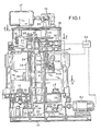
- the reference numeral 10 designates generally a fixed circular machine base on which is rigidly mounted an upstanding vertical column 11.
- the machine base rotatably supports a worktable 12 carrying a plurality of work-holding spindles 13.
- the construction of the machine shown in the drawings is more or less in accordance with that of the E. C. Bullard, et al. U.S. Patent No. 2,947,188, to which attention is directed for more specific details of construction and operation of equipment of this type.
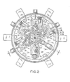
- the circular worktable 12 has six equally divided segments, each of which mounts a pair of work-holding spindles 13 (see Fig. 3).
- the worktable is annular in form and rotates about the fixed central column 11.
- the central column 11 of the equipment is, like the worktable, divided into six equal segments, each constituting a work station. Five of those segments are machining stations, and are provided with tool holding slides 14, 14a (Fig. 1). The sixth position on the column is left open, and is used for loading and unloading of workpieces.
- a feed works platform 15 At the top of the column 11 is a feed works platform 15, on which are mounted a plurality of individual feed works mechanisms 16.
- individual feed works units 16 In a conventional machine of the type described in the E. C. Bullard, et al. U.S. Patent No. 2,947,188, there are five such individual feed works units 16, one for each of the tool slides 14.
- the equipment only includes four feed works mechanisms, one for each of the first four 'tool slides 14.
- the fifth tool slide 14a being the one in which the final machining operations are performed and being located immediately in advance of the load-unload station, is controlled and operated independently of the other stations.
- a primary drive motor 17 is mounted on a drive platform 18, at the top of the machine and serves to provide power for all of the functions of the machine, with the exception of the last machining station.
- the primary drive motor 17 is coupled through bevel gears 19, 20 to a vertical drive shaft 21.
- the shaft 21' is, in turn, connected through a drive pinion 22 and idler gear 23 to a bull gear 24.
- the bull-gear as will be described, drive in common each of the four feed works units 16, which are clustered radially around the bull gear, substantially as shown in Fig. 2.
- Each of the feed works units includes output means for driving the spindles at that station, as well as for driving the horizontal and vertical tool slides.
- the gear mechanisms illustrated to the right of the bull gear 24 represent in substance the mechanisms of a single feed works unit.
- the bull gear 24 drives a pinion 25 which, through a pair of gears 26, 27, drives a spindle transmission shaft 28.
- spindle speed change gears 29, 30 and a spindle drive shaft assembly 31, 32 spindle power is transmitted from the feed works level, at the top of the machine, to the housing 33 formed in the machine base 10.
- a synchronizer unit 34 which includes a combination friction clutch and positive drive connection for engagement with a spindle drive pinion 35.
- a pinion 36 at the lower end of the spindle drive shaft 32, meshes with a synchronizer gear 37, which thus rotates with the primary drive motor 17 at a speed determined by the change gears 29, 30.
- the synchronizer 34 is engaged with a mating synchronizer element 38, which is movable with the worktable, to drivingly engage the spindle mechanism which is then located above that particular synchronizer.
- the pinion 35 drives a pair of spindle gears 39 (only one being shown in Fig.
- the synchronizer mechanisms 34 remain fixed in the base housing 33. At the end of a particular machining operation, the several synchronizers are retracted to accommodate rotary indexing of the worktable, after which the synchronizer units are extended to engage the new spindle drive. Thus, as the spindles advance around the column, they are successively engaged by different synchronizer units and driven at different speeds appropriate to the particular machining operation being performed.
- the upper portion 31 of the spindle drive shaft has a worm gear portion 40 meshing with a work wheel 41, mounted on a feed takeoff shaft 42.
- the shaft 42 mounts a pinion 43 meshing with a feed drive gear 44.
- the drive gear 44 is selectively engaged to drive either fine feed or course feed change gears 47, 48, meshing with similar change gears 47a, 48a fixed to a shaft 49.
- the shaft 49 drives through a safety clutch 50 (which releases at a predetermined torque) a bevel pinion 51 meshing with a corresponding bevel gear 52.
- the bevel gear 52 in turn drives through a gear set 53, 54, shaft 55 and clutch 56 a pair of feed gears 57, 58.
- the feed gear 58 drives a shaft 59 threadedly engaged with the corresponding vertical slide block 14.
- the threaded shaft 59 is rotated, either at the fine feed rate or at the course feed rate, depending on the position of the clutches 45, 46.
- both vertical and horizontal tool feed motions are derived from controlled rotation of the threaded shaft 59, through a series of mechanical interlocks which, after a predetermined degree of vertical movement of the slide, convert any further shaft rotation into horizontal translation movement of a horizontal tool slide 60.
- a drive shaft 61 which mounts the gear 58 and connects with the threaded shaft 59, may be driven by a gear 62 (down direction) or 63 (up direction), depending upon which, if either, of clutches 64,65 is engaged. If either of the clutches 64, 65 is engaged, the feed clutch 56 is disengaged and the threaded shaft 59 rotates at traversing speed, either in the up or down direction as the case may be.
- the timing of the clutches 45,46,56,64 and 65 may be controlled by a cam drum rotated by a worm wheel connected through a worm wheel to the feed drive gear 57.
- Indexing of the rotary worktable 12 is effected by a Geneva-like mechanism in the form of a rotary arm 69 which, when driven through a full revolution, advances the rotary worktable 12 through one sixth of a revolution, to advance the workpieces one station.
- the index arm is driven by a worm wheel 70 from a worm gear-71 carried on an index drive shaft 72.
- Bevel gears 73, 74 connect the index drive shaft to a vertical shaft 75, which extends upward into the feed works level of the machine and there is connected through gears 76-78 with a shaft 79.
- the latter is connected through a brake-clutch mechanism 80, to a drive gear 81 driven directly from the transmission shaft 21 through the pinion 22.
- the feed works for one of the machining stations, advantageously, is omitted entirely, so that neither the tool slide nor the spindles at the modified station are connected to the mechanical drive system.
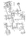
- a modified form of synchonizer 90 (Fig. 5) driven by gears 36a, 37a corresponding in general to gears 36, 37 of the conventional synchronizer 34.
- the drive input gear 36a is connected through bevel gears 91, 92 to an independently controlled, external drive motor 93, advantageously a variable speed DC electric motor.
- the synchronizer 90 is in general similar to the synchronizers 34, having a friction clutch element 94 and a splined mechanically engaging element 95.
- the friction element 94 of the synchronizer when the worktable is in an indexing position, ready to start a new machining operation, the friction element 94 of the synchronizer, being driven at the desired speed, is elevated controllably by hydraulic control means.
- the friction element 94 engages a corresponding element 38 connected to the spindle gear 35.
- the frictional relationship causes the gear 35 and the connected pair of spindles 13 to be accelerated up to the desired rotary speed, after which the splined element 95 is elevated into a fixed mechanically connected drive relationship.
- the spindle pairs at machining stations one-four are controllably driven at fixed speeds, which may be different at each station, as a function of the speed of the primary drive motor 17 and the spindle change gear combinations 29, 30 at each station.
- the spindle pair at the fifth machining station is driven independently, at speeds which may vary during the machining sequence, by means of the variable speed motor 93.
- the variable speed operation is under the control of a computerized numerical control system 94, which may in itself be of known and readily available commercial design.
- the modified machining station utilizes independently controlled vertical and horizontal slides 14a, 60a.
- the vertical slide 14a is slideably engageable with fixed vertical guide rails 100 secured to the central vertical column 11, it being understood that similar pairs of guide rails are spaced equidistantly about the column for the mounting the tool slide at stations one-four.
- the column 11 has a recess 101 formed in its face, which receive guide bars 102 fixed to the vertical slide 14a.
- a threaded shaft 103 is connected to the vertical slide 14a through a ball screw element 104.
- the shaft 103 is not, however, connected to a mechanical feed works mechanism, but instead extends upwardly through the feed works platform 15, where it is connected through bevel gears 105,106 to a servo motor 107, which may be of conventional design, adapted for controlled operation by the computerized numerical control unit (CNC unit) 94.
- CNC unit computerized numerical control unit
- the threaded shaft 103 of the modified machining station provides only a vertical compo- . nent of motion.
- Horizontal or transverse motion is provided by a second servo motor 108, also connected to the CNC control unit 94, which is engaged through bevel gears 109, 110 to a threaded shaft and ball screw assembly 111, 112.
- the ball screw 112 is secured to a transversely movable tool slide 60a, on which appropriate cutting tools are mounted.
- each of the tool slides 60, 60a will mount at least two cutting tools for simultaneous operation on the workpiece of each spindle of a pair.
- the servo motor 108 for transverse tool motion, is advantageously mounted directly on the vertically movable tool slide 14a, for up and down movement along with the slide. While it would be possible to mount the motor 108 in fixed position on the feed works platform, and utilize a splined shaft or the like for a movable mechanical connection, it is greatly preferred to movably mount the servo motor 108 and connect it to its drive and control source by means of flexible conductors (not shown). As shown particularly in Fig.
- the servo motor 108 may advantageously be mounted on the vertical slide 14a with its axis directed generally downward at a slight angle to the axis of the main column 11, so as to be disposed generally within the physical outlines of the vertical slide 14a, enabling the modified slide unit to be received generally within the same space as is provided for a conventional slide unit.
- machining operations of much greater complexity may be carried out with the modified "Mult-Au-Matic" type unit.
- the rates of horizontal and vertical tool feed movement may be varied, either together or one with respect to the other, to accomplish rather complex contouring operations.
- spindle speed may be varied during the course of the machining operations, as may be appropriate to the diameter being cut at any movement and/or the precise nature of the operation.
- the CNC unit can be programmed to compensate for individual dimensional positioning errors in each of the spindle pairs, as they are progressively brought into the number five or final finishing position.
- a typical "Mult-Au-Matic" type rotary indexing machine may have a worktable diameter on the order of six feet. Working with equipment of such massive size, experience has indicated that there may be minor variations in the positioning of the individual work stations at any given location. This has served in the past to limit machining tolerances to approximately plus or minus 0.0005.
- the positional variation of each spindle station at the finish or number five position may be precisely measured, and the coordinates of any variation from intended position can be programmed into the CNC control for each position. Accordingly, when worktable position number one, for example, is indexed into the number five machining position, its previosuly measured positional variation is known to the CNC unit, and the instructions to the servo motors 107,108 provide a corresponding offset. Since the positional variation for each worktable position may be slightly different, the CNC unit is preprogrammed separately with respect to each such worktable position and the appropriate offset is automatically introduced at each new index of the rotary worktable.
- the system of the invention is further advantageous in permitting multiple pass threading operations to be performed at the finish machining station.
- threading could only be accomplished if done in a single pass, which usually is not practicable.
- the precise rotary position of the spindle at any time is known to the CNC unit, through its control of the motor 93 in conjunction with a positional feedback sensor (not shown), which may be of conventional and well known type.
- the finish machining unit, at the modified station may be utilized to make several threading passes, if necessary, in each instance commencing the pass at a given rotational position of the work.
- the system of the invention significantly extends the usefulness of multiple spindle, rotary indexing machine tool centers, such as the "Mult-Au-Matic" type L Vertical Chucking Machine.
- the well known and thoroughly tested advantages of such machine may be principally retained while, at the same time, permitting for the first time the manufacture of parts of more complex design, finished to extremely close tolerances (reliably to plus or minus 0.0001), and also permitting threading operations, for example, to be performed.
- the CNC control machining station is operable in sequence with each of a succession of spindle stations, which have previously been advanced through a plurality of mechanically coordinated machining steps, operating from a single common drive motor.
- the operational output of the CNC control is significantly greater than if an effort were made to perform the entire machining operation with one or more CNC controlled units. Because these units involve very significant expense, as compared to the mechanically coordinated units, important economic advantages are realized in the modified, combination machine tool center, in which mechanically coordinated units perform most of the basic machining operations where greater precision is required and/or the mechanical units are incapable of performing the operation.
- CNC controls which are available commercially, would be suitable for the purposes of the invention.
- One such control is the Allen Bradley series 7100 computerized numerical control system, as available on the filing hereof from Allen Bradley Company, Cleveland, Ohio.
- the concept of the invention not only enormously enlarges the potential uses of multiple spindle, rotary indexing vertical chucking machines, but also is designed so as to be suitable for retrofit installation in existing machines, enabling those machines to be upgraded significantly to more modern production requirements.
Landscapes
- Engineering & Computer Science (AREA)
- Mechanical Engineering (AREA)
- Machine Tool Units (AREA)
- Machine Tool Positioning Apparatuses (AREA)
Claims (6)
Applications Claiming Priority (2)
| Application Number | Priority Date | Filing Date | Title |
|---|---|---|---|
| US182212 | 1980-08-28 | ||
| US06/182,212 US4351096A (en) | 1980-08-28 | 1980-08-28 | Multiple spindle rotary indexing machine tool |
Publications (3)
| Publication Number | Publication Date |
|---|---|
| EP0046883A2 EP0046883A2 (de) | 1982-03-10 |
| EP0046883A3 EP0046883A3 (en) | 1983-07-27 |
| EP0046883B1 true EP0046883B1 (de) | 1985-09-18 |
Family
ID=22667498
Family Applications (1)
| Application Number | Title | Priority Date | Filing Date |
|---|---|---|---|
| EP81105958A Expired EP0046883B1 (de) | 1980-08-28 | 1981-07-28 | Mehrspindelwerkzeugmaschinen mit Winkelteilung |
Country Status (4)
| Country | Link |
|---|---|
| US (1) | US4351096A (de) |
| EP (1) | EP0046883B1 (de) |
| JP (1) | JPS5771760A (de) |
| DE (1) | DE3172344D1 (de) |
Families Citing this family (19)
| Publication number | Priority date | Publication date | Assignee | Title |
|---|---|---|---|---|
| US4655652A (en) * | 1982-02-03 | 1987-04-07 | The O.S. Kelly Company | Method of multiple station drilling |
| DE3216891A1 (de) * | 1982-05-06 | 1983-11-10 | Index-Werke Kg Hahn & Tessky, 7300 Esslingen | Mehrspindel-revolerverdrehautomat |
| DE3328230A1 (de) * | 1983-08-04 | 1985-02-21 | Brose Werkzeugmaschinen GmbH & Co KG, 8000 München | Vorrichtung zur variablen bearbeitung von werkstuecken |
| US4642861A (en) * | 1983-09-12 | 1987-02-17 | Saginaw Machine Systems, Inc. | Machine tool construction |
| US4779318A (en) * | 1986-04-23 | 1988-10-25 | Litton Industrial Automation Systems, Inc. | Multiple spindle machine having independently variable speed and feed rates |
| CH671723A5 (de) * | 1988-03-08 | 1989-09-29 | Azypatent Ag | |
| US5042126A (en) * | 1988-08-16 | 1991-08-27 | Tornos-Bechler Sa, Fabrique De Machines Moutier | Drive apparatus for multi-spindle processing machines |
| JP2895071B2 (ja) * | 1988-10-11 | 1999-05-24 | ファナック株式会社 | Nc加工方法 |
| IT1252152B (it) * | 1991-12-03 | 1995-06-05 | Porta Srl | Struttura di morsa girevole, applicabile particolarmente sulla tavola rotante di una macchina transfer |
| DE4211348C2 (de) * | 1992-04-04 | 1994-06-23 | Chiron Werke Gmbh | Energieführungsleitung an einer Werkzeugmaschine mit einem Drehtisch |
| US5459915A (en) * | 1994-04-15 | 1995-10-24 | Devlieg-Bullard, Inc. | High accuracy machining station for a multiple spindle rotary indexing machine tool |
| EP0989922B1 (de) * | 1997-06-21 | 2003-09-03 | Feintool International Holding | Montage- oder fertigungsautomat und arbeitsstation für einen solchen automaten |
| KR100321138B1 (ko) * | 1999-06-04 | 2002-03-18 | 김재복 | 2 스핀들을 부착한 3축 이송의 에어콘용 스크롤 가공기 |
| AUPQ120499A0 (en) | 1999-06-25 | 1999-07-22 | K D Binnie Engineering Pty Ltd (As Trustees For K D Binnie Engineering Superannuation Fund) | A lathe |
| AU775352B2 (en) * | 1999-06-25 | 2004-07-29 | K D Binnie Engineering Pty Ltd | A lathe |
| US6219895B1 (en) * | 2000-06-27 | 2001-04-24 | Davenport Industries, Llc | Machine tool with servo drive mechanism |
| CN102490023B (zh) * | 2011-12-26 | 2014-06-18 | 黄山皖南机床有限公司 | 一种数控机床二轴联动旋转工作台 |
| JP5966100B1 (ja) | 2014-09-05 | 2016-08-10 | ヤマザキマザック株式会社 | 工作機械 |
| CN109843502B (zh) | 2017-07-04 | 2022-09-13 | 米克朗自动化设备有限公司 | 旋转传送分度机 |
Family Cites Families (6)
| Publication number | Priority date | Publication date | Assignee | Title |
|---|---|---|---|---|
| US2947188A (en) * | 1955-01-31 | 1960-08-02 | Bullard Co | Synchronizing device |
| CH435918A (de) * | 1963-07-24 | 1967-05-15 | Gildemeister Werkzeugmasch | Mehrspindel-Futter-Drehautomat |
| US3792633A (en) * | 1973-04-02 | 1974-02-19 | V Kogtev | Vertical multispindle continuous lathe |
| US3854353A (en) * | 1973-06-20 | 1974-12-17 | Bendix Corp | Method and apparatus for performing a threading operation on a rotating workpiece |
| US4159660A (en) * | 1978-02-21 | 1979-07-03 | Ex-Cell-O Corporation | Biaxial turning machine with means for bidirectional independent tool compensation |
| US4255991A (en) * | 1979-05-04 | 1981-03-17 | Lambert Robert D | Method and apparatus for electromechanically retro-fitting a conventional automatic screw machine to accept numerical control |
-
1980
- 1980-08-28 US US06/182,212 patent/US4351096A/en not_active Expired - Lifetime
-
1981
- 1981-07-28 EP EP81105958A patent/EP0046883B1/de not_active Expired
- 1981-07-28 DE DE8181105958T patent/DE3172344D1/de not_active Expired
- 1981-08-27 JP JP56133419A patent/JPS5771760A/ja active Pending
Also Published As
| Publication number | Publication date |
|---|---|
| US4351096A (en) | 1982-09-28 |
| EP0046883A3 (en) | 1983-07-27 |
| EP0046883A2 (de) | 1982-03-10 |
| DE3172344D1 (en) | 1985-10-24 |
| JPS5771760A (en) | 1982-05-04 |
Similar Documents
| Publication | Publication Date | Title |
|---|---|---|
| EP0046883B1 (de) | Mehrspindelwerkzeugmaschinen mit Winkelteilung | |
| EP0000874B1 (de) | Werkzeugmaschine mit gemeinschaftlichem Antrieb für Arbeitstisch und Förderer oder Werkstückträger | |
| US5300006A (en) | Automatic tool changer | |
| JPH04269137A (ja) | 複合加工工作機械 | |
| GB2121713A (en) | Multispindle-automatic turret lathe | |
| GB2178558A (en) | Thread cutting machines | |
| US4704773A (en) | Machine tool structure | |
| CN1330579A (zh) | 加工经过粗加工的有齿工件如齿轮的方法和机床 | |
| US4197769A (en) | Dual spindle NC chucking/turning machine | |
| CA1046807A (en) | Machine tool with counterposed rotary toolheads carrying cross-feed tool slides | |
| CN108747440A (zh) | 多功能数控加工中心 | |
| EP0088131B1 (de) | Selbsttätige werkzeugaustauschanordnung für werkzeugmaschine | |
| GB1331546A (en) | Machine for high speed high precision machining of small parts | |
| US4327612A (en) | Turret lathe | |
| US4797991A (en) | Vertical machining center | |
| US2096754A (en) | Machine tool | |
| CN208801018U (zh) | 高精度数控加工中心 | |
| US3101649A (en) | Spiral milling machine | |
| US3158053A (en) | Multi-spindle lathe | |
| JP2807823B2 (ja) | 2主軸対向型cnc旋盤のワーク加工装置 | |
| US5735029A (en) | Flexible arbor mill machine | |
| US4528876A (en) | Universal single spindle pin crankshaft lathe | |
| CN103302498A (zh) | 车滚铣复合机床 | |
| US2986055A (en) | Contour chasing lathe and method of operation | |
| CN208801043U (zh) | 多功能数控加工中心 |
Legal Events
| Date | Code | Title | Description |
|---|---|---|---|
| PUAI | Public reference made under article 153(3) epc to a published international application that has entered the european phase |
Free format text: ORIGINAL CODE: 0009012 |
|
| AK | Designated contracting states |
Designated state(s): AT BE CH DE FR GB IT LU NL SE |
|
| 17P | Request for examination filed |
Effective date: 19820819 |
|
| PUAL | Search report despatched |
Free format text: ORIGINAL CODE: 0009013 |
|
| AK | Designated contracting states |
Designated state(s): AT BE CH DE FR GB IT LI LU NL SE |
|
| RBV | Designated contracting states (corrected) |
Designated state(s): DE GB |
|
| GRAA | (expected) grant |
Free format text: ORIGINAL CODE: 0009210 |
|
| AK | Designated contracting states |
Designated state(s): DE GB |
|
| REF | Corresponds to: |
Ref document number: 3172344 Country of ref document: DE Date of ref document: 19851024 |
|
| PLBI | Opposition filed |
Free format text: ORIGINAL CODE: 0009260 |
|
| 26 | Opposition filed |
Opponent name: FIRMA ALFRED H. SCHUETTE Effective date: 19860613 |
|
| PG25 | Lapsed in a contracting state [announced via postgrant information from national office to epo] |
Ref country code: GB Effective date: 19880728 |
|
| RDAG | Patent revoked |
Free format text: ORIGINAL CODE: 0009271 |
|
| STAA | Information on the status of an ep patent application or granted ep patent |
Free format text: STATUS: PATENT REVOKED |
|
| 27W | Patent revoked |
Effective date: 19880929 |
|
| GBPR | Gb: patent revoked under art. 102 of the ep convention designating the uk as contracting state | ||
| GBPC | Gb: european patent ceased through non-payment of renewal fee |