EP0047003A2 - Anémomètre pyroélectrique - Google Patents
Anémomètre pyroélectrique Download PDFInfo
- Publication number
- EP0047003A2 EP0047003A2 EP81106744A EP81106744A EP0047003A2 EP 0047003 A2 EP0047003 A2 EP 0047003A2 EP 81106744 A EP81106744 A EP 81106744A EP 81106744 A EP81106744 A EP 81106744A EP 0047003 A2 EP0047003 A2 EP 0047003A2
- Authority
- EP
- European Patent Office
- Prior art keywords
- substrate
- heater element
- flow rate
- output
- indicator according
- Prior art date
- Legal status (The legal status is an assumption and is not a legal conclusion. Google has not performed a legal analysis and makes no representation as to the accuracy of the status listed.)
- Withdrawn
Links
Images

Classifications
-
- G—PHYSICS
- G01—MEASURING; TESTING
- G01F—MEASURING VOLUME, VOLUME FLOW, MASS FLOW OR LIQUID LEVEL; METERING BY VOLUME
- G01F1/00—Measuring the volume flow or mass flow of fluid or fluent solid material wherein the fluid passes through a meter in a continuous flow
- G01F1/68—Measuring the volume flow or mass flow of fluid or fluent solid material wherein the fluid passes through a meter in a continuous flow by using thermal effects
- G01F1/684—Structural arrangements; Mounting of elements, e.g. in relation to fluid flow
- G01F1/688—Structural arrangements; Mounting of elements, e.g. in relation to fluid flow using a particular type of heating, cooling or sensing element
- G01F1/6886—Pyroelectric elements
-
- G—PHYSICS
- G01—MEASURING; TESTING
- G01F—MEASURING VOLUME, VOLUME FLOW, MASS FLOW OR LIQUID LEVEL; METERING BY VOLUME
- G01F1/00—Measuring the volume flow or mass flow of fluid or fluent solid material wherein the fluid passes through a meter in a continuous flow
- G01F1/68—Measuring the volume flow or mass flow of fluid or fluent solid material wherein the fluid passes through a meter in a continuous flow by using thermal effects
Definitions
- the present invention relates to the measurement of fluid flow in general and to a pyroelectric anemometer in particular.
- HWA hot wire anemometer
- Upstream and downstream transistors are, respectively, cooled and heated by the flowing gas in combination with the heating transistor.
- the difference in temperature between the two transistors causes a variation in their gain and thus their output signal and are indicative of flow velocity.
- the output signal from the transistor anemometer is a non-linear function of the flow velocity unless a number of conditions are met and substantial signal processing is utilized.
- a further type of flow measuring device is disclosed in U.S. Patent 3,519,924 to Burton in which a piezoelectric oscillator is heated by a heating element and the heat transfer from the oscillator to the fluid is a function of the fluid velocity and can be measured by comparing the frequency of oscillation of the test oscillator with an isolated reference oscillator.
- an object of the present invention to provide an anemometer having an electrical output which is a function of the velocity of fluid flow in the device.
- pyroelectric materials which have a high thermal sensitivity in conjunction with a heater element to provide a voltage output which, when squared, is proportional to the velocity of the gas flow.
- Upstream and downstream electrodes on a pyroelectric substrate measure the charge redistribution due to heat from a centrally located heating element on the substrate. When a flow is present over the substrate, the upstream electrode will be cooled to a greater extent than will the downstream electrode and thus its temperature will be lower and thus the charge redistribution associated with the electrode will be less than the charge distribution associated with the downstream electrode.
- the electrodes are connected to a differential amplifier whose output is connected to a further amplifier and an electronic meter.
- a means for heating the substrate in a fluctuating manner in order to permit the necessary charge redistribution is further provided.
- the output of the two electrodes will vary and in addition the amplitude of their outputs is affected depending on whether they are upstream or downstream of the heating element. The extent of the difference in the signal from the two electrodes is indicative of the flew velocity.
- the electric polarization along a certain crystallographic axis may not vanish. Changing the temperature in such crystals, produces a change in the electric polarization. This phenomenon is referred to as the pyroelectric effect and the parameter relating the temperature change and the surface charge is called the pyroelectric coefficient. All pyroelectric crystals have non- centrosymmetric structures and, as a consequence, are also piezoelectric.
- a small substrate of pyroelectric material has suitable electrodes attached thereto, and is heated, a surface charge will be formed which can be measured at the electrodes.
- the induced surface charge on the electrodes will gradually discharge through the external measuring circuitry to produce a net zero charge on the electrodes when the pyroelectric substrate has been maintained at an elevated temperature for some period of time. Because of this reason, pyroelectric structures have not been considered for use in flow measurement applications. For example, if a small heater were utilized to raise the temperature of the substrate a charge would be developed. However over a period of time this charge would redistribute back to produce a net zero voltage across the electrodes.
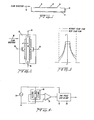
- Figure 1 is a cross-sectional view of a pyroelectric substrate 10 having a base electrode 12 thereon.
- a heater element 14 is centrally disposed on the upper surface of the substrate with adjacent sensor electrodes A and B.
- the flow direction is indicated by arrow 16.
- the orientation of the Figure 1 structure can be seen in plan view Figure 2 which additionally has heater element leads 18 and sensor electrode leads 20 and 22 for sensor electrodes A and B , respectively.
- the operation of this embodiment of the present invention is as follows.
- the pyroelectric charge redistribution output measured at sensor electrode A and sensor electrode B should be identical and there will be no difference between their outputs.
- Figure 4 illustrates the electrical processing circuitry for one embodiment of the present invention in which a sinusoidal output is applied to heater element 14 by fluctuating power supply 24.
- the base electrode (not shown) would be grounded with sensor electrodes A and B connected to the inputs of a low-noise, high input impedance (on the order of 100 megohms) differential amplifier 26.
- the differential amplifier provides an output which is a function of the difference in the two inputs.
- the output is. supplied to a two phase lock-in-amplifier 28 which also has a reference input from the fluctuating power supply.
- the heater input from power supply 24 is a sine wave alternating current going both positive and negative.
- the negative going portion of the sine wave supplies the same heat pulse as does the positive going portion of the sine wave and consequently the heat pulses supplied to the substrate 10 are at a frequency twice that of the sinusoidal input. Therefore in a preferred embodiment the lock-in-amplifier will be set to the 2F mode with respect to the input reference frequency F.
- sensor electrodes A and B have identical outputs and the differential amplifier would provide no difference output to the lock-in-amplifier.
- the output from sensor A is substantially reduced in amplitude due to the fact that it is upstream flowwise from. the heater element and is cooled by the flow of fluid thereover.
- the downstream sensor B in addition to being heated by heat transfer through the substrate is also heated by the fluid flowing over the heating element which is transferring heat to the sensor electrode and substrate therebeneath and consequently has a substantially larger fluctuating output. Because there is a substantial difference in the outputs of sensor electrodes A and B, the differential amplifier will provide an output fluctuating at the same frequency as the sensor outputs.
- the magnitude of the differential signal will increase with flow rate and eventually will saturate when the redistribution of the thermal heat flow saturates, i.e., the temperature distribution can no longer be influenced by the fluid flow.
- the output 30 will be a function of the velocity and heat transfer characteristics of the fluid flowing over the pyroelectric anemometer.
- thermal conductivity indicator In the event that the flow characteristics of the fluid are known, changes in the thermal conductivity of the fluid will be reflected in the output signal.
- This aspect permits structure identical to the anemometer to be used as a thermal conductivity indicator. This is important in binary gas mixtures in determining the concentration of the gases if they have different thermal conductivities.
- the thermal conductivity indicator has application in gas and liquid chromatography.
- LiTa0 3 lithium tantalate
- LiTaO 3 has several advantages over other'pyroelectric materials. It has a high Curie temperature (891 degrees K), good mechanical behavior and is relatively insensitive to the ambient temperature. Furthermore, it is easy to scribe and break into smaller pieces as is commonly done with silicon wafers and lends itself to photolithographic procedures. Other materials such as plastic pyroelectrics and other crystalline pyroelectrics can be used for different applications. Although much smaller sizes can be utilized, one embodiment of the present invention comprised a pyroelectric substrate surface area of 4 x 8 mm with a thickness of either 0.3 mm or, 0.06 mm.
- Both the sensor electrodes and the heater element 14 comprise vapor deposited nichrome films on the polished side of the pyroelectric substrate.
- Other materials could be utilized for the heater and/or the sensor electrodes although the nichrome film approximately 1.0 um thick provides a resistance of around 60 ohms and thus provides a good heater element.
- Convenience suggests using the same material for the sensor electrodes which can be deposited at the same time.
- the electrode/heater separation distance d in preferred embodiments was 0.25 mm or 2.0 mm.
- the base electrode 12 was also a vapor deposited nichrome film again due to convenience, although it could just as easily have been aluminum, gold or any other conductor.
- the base electrode 12 is of course necessary in order to comprise a capacitor with the respective sensor electrodes which then permits the pyroelectric effect to generate a charge on the capacitor due to charge displacements in the dielectric material comprising the pyroelectric substrate.
- the separation distance d between the heater and the sensor electrodes will affect the flow response of the pyroelectric anemometer. If d is small compared to the width of the heater element, there will be practically no temperature difference between the heater element and the sensor electrode. On the other hand, if this distance is too large in comparison with the heater width, then practically no thermal energy reaches the electrodes. Tests have shown that while d can be as large as 8 mm, if d is approximately equal to the width of the heater element the average temperature in the electrode region is much smaller than the strip temperature but that the electrodes will be close enough to receive substantial heat energy therefrom.
- the thickness of the substrate has a substantial effect upon the frequency dependence of the pyroelectric response. For a given thickness, the magnitude of the pyroelectric response decreases as the frequency increases. However, the thinner the pyroelectric substrate, the higher the frequency-response.
- a 3 hz heater drive signal supplied by power .supply 24 may be a lower fluctuation frequency limit (the use of frequencies much lower than this causes substantial noise in the sensor electrode outputs) but higher frequencies can be used if the pyroelectric substrate is thin and small enough and the flow velocities to be measured are high enough. Because a higher flow rate transfers heat faster, it will have a higher response. time. It has been noted that drive signals above 5 hz are relatively quiet and free from electronic noise which is observed at the lower drive frequencies.
- a preferred embodiment of the present invention utilizes upstream and downstream sensor electrodes, and in addition measures the difference in temperature between the two, this device is relatively insensitive to the ambient temperature of the fluid flowing thereover in marked contrast to the hot wire anemometer which is very sensitive to ambient flow temperature change.
- the size of the structures can be reduced considerably beyond the dimensions disclosed herein..It is easily conceivable that the total plate area of the anemometer could be 1 mm 2 or less. This small size should not cause any serious degradation of the accuracy of the anemometer and should, additionally, increase the response rate thereof. Furthermore, with the modern fabrication technology, the reproduceability of the pyroelectric anemometer is outstanding and it is not unreasonable to expect commercially manufactured anemometers to have identical characteristics within a percent or two.
- the transistor anemometer is very highly temperature dependent in that slight variations in the fabrication of the two identical transistors on either side of the heater source will cause changes in their response slopes and consequently a change in the ambient temperature changes the difference voltages which will be reflective of the flow velocity. Additionally, the signal level is relatively low (2 uv per m/sec.) requiring extremely sensitive signal measuring devices.
- a pyroelectric anemometer can be constructed which has both high sensitivity and a wide range of flow response. Utilizing the application of a fluctuating heat source in combination with the differential measurement, eliminates many of the problems of other anemometers.
- the sensitivity of the pyroelectric anemometer is such that it can accurately measure gas flow rates as low as 1 cm/min. and as high as 2000 cm/min. with the same instrument.
- the flow rate response is essentially insensitive to the temperature of the flowing liquid.
- variations in the pyroelectric substrate thickness, electrode/heater distance, and heater fluctuation frequency can be adjusted for optimum-results.
- the pyroelectric anemometer also demonstrates a certain amount of direction dependence which meets the empirical equations developed for hot wire anemometers. If the flow direction is perpendicular to the heater and sensor electrodes, the maximum output is achieved and ⁇ equals 0 ( ⁇ is the angle that the flow direction makes with respect to a perpendicular to the heater/sensor electrode orientation). However, as ⁇ increases, up to 90 degrees, the output will gradually decrease to 0 in accordance with U ⁇ is approximately equal to U O (Cos ⁇ ) 1 / 2 where U ⁇ is the actual output at the flow angle ⁇ and Uo is the output of the flow at equals 0.
- a pyroelectric anemometer could provide a good indication of flow direction.
- two pyroelectric anemometers oriented at 90 degrees with respect to each other as shown in Figure 6, an accurate indication of both flow rate and direction can be obtained because each anemometer would accurately provide the velocity of a component of the flow perpendicular to its heater/sensor electrode orientation.
- the Pythagorean theorum would provide the actual flow velocity (U actual equals the square root of U 1 2 +U 2 2 ).
- two pyroelectric anemometers could provide rate and direction information relatively easily.
Landscapes
- Physics & Mathematics (AREA)
- Fluid Mechanics (AREA)
- General Physics & Mathematics (AREA)
- Measuring Volume Flow (AREA)
Applications Claiming Priority (2)
| Application Number | Priority Date | Filing Date | Title |
|---|---|---|---|
| US06/182,683 US4332157A (en) | 1980-08-29 | 1980-08-29 | Pyroelectric anemometer |
| US182683 | 1988-04-18 |
Publications (2)
| Publication Number | Publication Date |
|---|---|
| EP0047003A2 true EP0047003A2 (fr) | 1982-03-10 |
| EP0047003A3 EP0047003A3 (fr) | 1984-05-16 |
Family
ID=22669565
Family Applications (1)
| Application Number | Title | Priority Date | Filing Date |
|---|---|---|---|
| EP81106744A Withdrawn EP0047003A3 (fr) | 1980-08-29 | 1981-08-28 | Anémomètre pyroélectrique |
Country Status (4)
| Country | Link |
|---|---|
| US (1) | US4332157A (fr) |
| EP (1) | EP0047003A3 (fr) |
| JP (1) | JPS57118161A (fr) |
| CA (1) | CA1168468A (fr) |
Cited By (1)
| Publication number | Priority date | Publication date | Assignee | Title |
|---|---|---|---|---|
| EP0313120A1 (fr) * | 1987-09-18 | 1989-04-26 | Bronkhorst High-Tech B.V. | Indicateur de débit sensible à la direction |
Families Citing this family (31)
| Publication number | Priority date | Publication date | Assignee | Title |
|---|---|---|---|---|
| JPS56162014A (en) * | 1980-05-16 | 1981-12-12 | Nippon Denso Co Ltd | Measuring device for flow rate of gas |
| US4453405A (en) * | 1982-05-24 | 1984-06-12 | Trustees Of The University Of Pennsylvania | Pyroelectric vorticimeter |
| US4551425A (en) * | 1982-09-28 | 1985-11-05 | Trustees Of The University Of Pennsylvania | Pyroelectric gas sensor |
| US4555940A (en) * | 1982-11-01 | 1985-12-03 | Renger Herman L | Method and apparatus for measuring fluid flow rates and volumes through fluid flow paths |
| US4542650A (en) * | 1983-08-26 | 1985-09-24 | Innovus | Thermal mass flow meter |
| US4576050A (en) * | 1984-08-29 | 1986-03-18 | General Motors Corporation | Thermal diffusion fluid flow sensor |
| US4713970A (en) * | 1984-08-29 | 1987-12-22 | General Motors Corporation | Thermal diffusion fluid flow sensor |
| US4608865A (en) * | 1984-12-05 | 1986-09-02 | The Regents Of The University Of California | Integrated pyroelectric sensor and method |
| US4726225A (en) * | 1986-08-22 | 1988-02-23 | Johnson Service Company | Surface acoustic wave gas flow rate sensor with self-heating feature |
| JPH0663799B2 (ja) * | 1987-10-05 | 1994-08-22 | 株式会社村田製作所 | 熱型流量検出装置 |
| US4909078A (en) * | 1987-10-14 | 1990-03-20 | Rosemount Inc. | Fluid flow detector |
| US5030012A (en) * | 1989-02-02 | 1991-07-09 | The United States Of America As Represented By The Department Of Health And Human Services | Pyroelectric calorimeter |
| CA2015812A1 (fr) * | 1989-05-02 | 1990-11-02 | Shiro Nakayama | Capteur d'acceleration piezoelectrique et dispositif a capteur d'acceleration piezoelectrique |
| US5218865A (en) * | 1990-08-16 | 1993-06-15 | Djorup Robert Sonny | Thermal anemometer transducer wind set |
| US5217019A (en) * | 1991-12-27 | 1993-06-08 | Abbott Laboratories | Apparatus and method for continuously monitoring cardiac output |
| US5263380A (en) * | 1992-02-18 | 1993-11-23 | General Motors Corporation | Differential AC anemometer |
| US5477734A (en) * | 1994-08-12 | 1995-12-26 | Gas Research Institute | Pyroelectric swirl measurement |
| US5463899A (en) * | 1994-08-12 | 1995-11-07 | Gas Research Institute | Simultaneous measurement of gas thermal conductivity and mass flow |
| US5515714A (en) * | 1994-11-17 | 1996-05-14 | General Motors Corporation | Vapor composition and flow sensor |
| US5795064A (en) * | 1995-09-29 | 1998-08-18 | Mathis Instruments Ltd. | Method for determining thermal properties of a sample |
| US5620002A (en) * | 1995-12-22 | 1997-04-15 | Abbott Critical Care Systems | Method for correcting thermal drift in cardiac output determination |
| NL1008665C1 (nl) * | 1998-03-20 | 1999-09-21 | Berkin Bv | Mediumstroommeter. |
| US6502459B1 (en) * | 2000-09-01 | 2003-01-07 | Honeywell International Inc. | Microsensor for measuring velocity and angular direction of an incoming air stream |
| US6631638B2 (en) | 2001-01-30 | 2003-10-14 | Rosemount Aerospace Inc. | Fluid flow sensor |
| DE10146321B4 (de) * | 2001-09-20 | 2008-08-14 | Robert Bosch Gmbh | Sensorbaustein mit einem Sensorelement, das von einem Heizelement umgeben ist |
| US7451657B2 (en) * | 2004-01-16 | 2008-11-18 | Jentek Sensors, Inc. | Material condition monitoring with multiple sensing modes |
| US8981018B2 (en) * | 2004-03-15 | 2015-03-17 | Jentek Sensors, Inc. | Internal material condition monitoring for control |
| US7243538B1 (en) * | 2005-12-22 | 2007-07-17 | Honeywell International Inc. | Gas flow sensor system and method of self-calibration |
| DE102007023824B4 (de) * | 2007-05-21 | 2010-01-07 | Abb Ag | Thermischer Massendurchflussmesser |
| DE102012108350B3 (de) * | 2012-09-07 | 2013-07-18 | Pierburg Gmbh | Vorrichtung und Verfahren zur Rekalibrierung eines Abgasmassenstromsensors |
| WO2015076117A1 (fr) * | 2013-11-20 | 2015-05-28 | 株式会社村田製作所 | Capteur de débit du type thermique |
Family Cites Families (6)
| Publication number | Priority date | Publication date | Assignee | Title |
|---|---|---|---|---|
| US3531663A (en) * | 1965-07-29 | 1970-09-29 | Exxon Research Engineering Co | Integral heater piezoelectric devices |
| US3519924A (en) * | 1967-09-22 | 1970-07-07 | Heath Lab Inc | Measurements systems using conductively-heated pyroelectric element |
| US3733499A (en) * | 1972-04-20 | 1973-05-15 | Westinghouse Electric Corp | Pyroelectric detector |
| US3896311A (en) * | 1974-01-02 | 1975-07-22 | Minnesota Mining & Mfg | Pyroelectric motion and temperature sensitive infrared detector with conductive fingers |
| DE2500897C3 (de) * | 1975-01-08 | 1982-10-14 | Böttcher, Bernhard, Dr.rer.nat. | Thermisches Verfahren zur Messung der Geschwindigkeitsverteilung in fluiden Medien |
| US4218620A (en) * | 1978-07-20 | 1980-08-19 | Eltec Instruments, Inc. | Pyroelectric detector having improved suspension means |
-
1980
- 1980-08-29 US US06/182,683 patent/US4332157A/en not_active Expired - Lifetime
-
1981
- 1981-08-27 CA CA000384694A patent/CA1168468A/fr not_active Expired
- 1981-08-28 EP EP81106744A patent/EP0047003A3/fr not_active Withdrawn
- 1981-08-28 JP JP56135383A patent/JPS57118161A/ja active Granted
Cited By (1)
| Publication number | Priority date | Publication date | Assignee | Title |
|---|---|---|---|---|
| EP0313120A1 (fr) * | 1987-09-18 | 1989-04-26 | Bronkhorst High-Tech B.V. | Indicateur de débit sensible à la direction |
Also Published As
| Publication number | Publication date |
|---|---|
| EP0047003A3 (fr) | 1984-05-16 |
| CA1168468A (fr) | 1984-06-05 |
| JPS6140346B2 (fr) | 1986-09-09 |
| JPS57118161A (en) | 1982-07-22 |
| US4332157A (en) | 1982-06-01 |
Similar Documents
| Publication | Publication Date | Title |
|---|---|---|
| US4332157A (en) | Pyroelectric anemometer | |
| US5463899A (en) | Simultaneous measurement of gas thermal conductivity and mass flow | |
| CA1230754A (fr) | Capteur de debit de fluide, a diffusion d'ondes thermiques | |
| US4378168A (en) | Dew point detection method and device | |
| US5003822A (en) | Acoustic wave microsensors for measuring fluid flow | |
| US4885937A (en) | Flow sensor | |
| US20040008471A1 (en) | Relative humidity sensor with integrated signal conditioning | |
| JPS59136620A (ja) | 流体の流量測定装置 | |
| US4713970A (en) | Thermal diffusion fluid flow sensor | |
| US6948361B2 (en) | Gasket flow sensing apparatus and method | |
| Leclercq et al. | Apparatus for simultaneous temperature and heat‐flow measurements under transient conditions | |
| US6508117B1 (en) | Thermally balanced mass air flow sensor | |
| Rahnamai et al. | Pyroelectric anemometers: preparation and flow velocity measurements | |
| US5477734A (en) | Pyroelectric swirl measurement | |
| US4453405A (en) | Pyroelectric vorticimeter | |
| Joshi | Surface-acoustic-wave (SAW) flow sensor | |
| US4361054A (en) | Hot-wire anemometer gyro pickoff | |
| Rahnamai et al. | Pyroelectric anemometers | |
| JPH06265565A (ja) | 気体の流速検出装置 | |
| Hsieh et al. | Pyroelectric anemometry: frequency, geometry and gas dependence | |
| JPS645260B2 (fr) | ||
| GB2243916A (en) | Pyroelectric anemometer | |
| RU2342640C1 (ru) | Датчик контроля уровня жидкости | |
| SU546821A1 (ru) | Термоанемометр | |
| RU9315U1 (ru) | Термоанемометр |
Legal Events
| Date | Code | Title | Description |
|---|---|---|---|
| PUAI | Public reference made under article 153(3) epc to a published international application that has entered the european phase |
Free format text: ORIGINAL CODE: 0009012 |
|
| AK | Designated contracting states |
Designated state(s): DE FR GB IT SE |
|
| PUAL | Search report despatched |
Free format text: ORIGINAL CODE: 0009013 |
|
| AK | Designated contracting states |
Designated state(s): DE FR GB IT SE |
|
| 17P | Request for examination filed |
Effective date: 19840730 |
|
| STAA | Information on the status of an ep patent application or granted ep patent |
Free format text: STATUS: THE APPLICATION IS DEEMED TO BE WITHDRAWN |
|
| 18D | Application deemed to be withdrawn |
Effective date: 19880301 |
|
| RIN1 | Information on inventor provided before grant (corrected) |
Inventor name: RAHNAMAI, HAMID Inventor name: ZEMEL, JAY N. PROF. |