EP0047113A2 - Dispositif de commande pour un robot industriel - Google Patents
Dispositif de commande pour un robot industriel Download PDFInfo
- Publication number
- EP0047113A2 EP0047113A2 EP81303830A EP81303830A EP0047113A2 EP 0047113 A2 EP0047113 A2 EP 0047113A2 EP 81303830 A EP81303830 A EP 81303830A EP 81303830 A EP81303830 A EP 81303830A EP 0047113 A2 EP0047113 A2 EP 0047113A2
- Authority
- EP
- European Patent Office
- Prior art keywords
- error
- error register
- control circuit
- register
- motor
- Prior art date
- Legal status (The legal status is an assumption and is not a legal conclusion. Google has not performed a legal analysis and makes no representation as to the accuracy of the status listed.)
- Withdrawn
Links
Images

Classifications
-
- G—PHYSICS
- G05—CONTROLLING; REGULATING
- G05B—CONTROL OR REGULATING SYSTEMS IN GENERAL; FUNCTIONAL ELEMENTS OF SUCH SYSTEMS; MONITORING OR TESTING ARRANGEMENTS FOR SUCH SYSTEMS OR ELEMENTS
- G05B19/00—Program-control systems
- G05B19/02—Program-control systems electric
- G05B19/18—Numerical control [NC], i.e. automatically operating machines, in particular machine tools, e.g. in a manufacturing environment, so as to execute positioning, movement or co-ordinated operations by means of program data in numerical form
- G05B19/19—Numerical control [NC], i.e. automatically operating machines, in particular machine tools, e.g. in a manufacturing environment, so as to execute positioning, movement or co-ordinated operations by means of program data in numerical form characterised by positioning or contouring control systems, e.g. to control position from one programmed point to another or to control movement along a programmed continuous path
- G05B19/21—Numerical control [NC], i.e. automatically operating machines, in particular machine tools, e.g. in a manufacturing environment, so as to execute positioning, movement or co-ordinated operations by means of program data in numerical form characterised by positioning or contouring control systems, e.g. to control position from one programmed point to another or to control movement along a programmed continuous path using an incremental digital measuring device
- G05B19/23—Numerical control [NC], i.e. automatically operating machines, in particular machine tools, e.g. in a manufacturing environment, so as to execute positioning, movement or co-ordinated operations by means of program data in numerical form characterised by positioning or contouring control systems, e.g. to control position from one programmed point to another or to control movement along a programmed continuous path using an incremental digital measuring device for point-to-point control
-
- G—PHYSICS
- G05—CONTROLLING; REGULATING
- G05B—CONTROL OR REGULATING SYSTEMS IN GENERAL; FUNCTIONAL ELEMENTS OF SUCH SYSTEMS; MONITORING OR TESTING ARRANGEMENTS FOR SUCH SYSTEMS OR ELEMENTS
- G05B19/00—Program-control systems
- G05B19/02—Program-control systems electric
- G05B19/18—Numerical control [NC], i.e. automatically operating machines, in particular machine tools, e.g. in a manufacturing environment, so as to execute positioning, movement or co-ordinated operations by means of program data in numerical form
- G05B19/19—Numerical control [NC], i.e. automatically operating machines, in particular machine tools, e.g. in a manufacturing environment, so as to execute positioning, movement or co-ordinated operations by means of program data in numerical form characterised by positioning or contouring control systems, e.g. to control position from one programmed point to another or to control movement along a programmed continuous path
- G05B19/21—Numerical control [NC], i.e. automatically operating machines, in particular machine tools, e.g. in a manufacturing environment, so as to execute positioning, movement or co-ordinated operations by means of program data in numerical form characterised by positioning or contouring control systems, e.g. to control position from one programmed point to another or to control movement along a programmed continuous path using an incremental digital measuring device
- G05B19/23—Numerical control [NC], i.e. automatically operating machines, in particular machine tools, e.g. in a manufacturing environment, so as to execute positioning, movement or co-ordinated operations by means of program data in numerical form characterised by positioning or contouring control systems, e.g. to control position from one programmed point to another or to control movement along a programmed continuous path using an incremental digital measuring device for point-to-point control
- G05B19/231—Numerical control [NC], i.e. automatically operating machines, in particular machine tools, e.g. in a manufacturing environment, so as to execute positioning, movement or co-ordinated operations by means of program data in numerical form characterised by positioning or contouring control systems, e.g. to control position from one programmed point to another or to control movement along a programmed continuous path using an incremental digital measuring device for point-to-point control the positional error is used to control continuously the servomotor according to its magnitude
- G05B19/232—Numerical control [NC], i.e. automatically operating machines, in particular machine tools, e.g. in a manufacturing environment, so as to execute positioning, movement or co-ordinated operations by means of program data in numerical form characterised by positioning or contouring control systems, e.g. to control position from one programmed point to another or to control movement along a programmed continuous path using an incremental digital measuring device for point-to-point control the positional error is used to control continuously the servomotor according to its magnitude with speed feedback only
-
- G—PHYSICS
- G05—CONTROLLING; REGULATING
- G05B—CONTROL OR REGULATING SYSTEMS IN GENERAL; FUNCTIONAL ELEMENTS OF SUCH SYSTEMS; MONITORING OR TESTING ARRANGEMENTS FOR SUCH SYSTEMS OR ELEMENTS
- G05B13/00—Adaptive control systems, i.e. systems automatically adjusting themselves to have a performance which is optimum according to some preassigned criterion
- G05B13/02—Adaptive control systems, i.e. systems automatically adjusting themselves to have a performance which is optimum according to some preassigned criterion electric
-
- G—PHYSICS
- G05—CONTROLLING; REGULATING
- G05B—CONTROL OR REGULATING SYSTEMS IN GENERAL; FUNCTIONAL ELEMENTS OF SUCH SYSTEMS; MONITORING OR TESTING ARRANGEMENTS FOR SUCH SYSTEMS OR ELEMENTS
- G05B2219/00—Program-control systems
- G05B2219/30—Nc systems
- G05B2219/41—Servomotor, servo controller till figures
- G05B2219/41024—High gain for low command speed, torque or position error equals or near zero
Definitions
- This invention relates to a control circuit for an industrial robot.
- the circuit receives a position command signal, determines the difference in the pulse numbers between the position command signal and a position feedback signal, the difference is set in an error register, the content of the error register is converted to an analog value by a digital-analog (DA) converter, and the motor is driven by a speed control device according to the analog value.
- DA digital-analog
- the circuit has only a constant relationship between the indicated value in the error register and the gain of the position gain multiplier, so that the circuit controls the output of the DA converter along straight lines corresponding to the error quantity set in the error register. Hence, satisfactory control regarding the error in the stopping position cannot always be obtained in the above-mentioned case.
- An object of the present invention is to provide an improved control circuit for an industrial robot.
- a control circuit for controlling an industrial robot in accordance with a position command signal and a position feedback signal, the control circuit comprising an error register, a digital-analog converter, and a position gain multiplier between the error register and the digital-analog converter, characterised in that when a motor which drives the robot stops rotating or gets ready to stop rotating and an error value held in the error register becomes higher than a predetermined value, the multiplication factor of the position gain multiplier is increased.
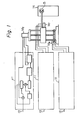
- blocks indicated by chain lines represent respective control circuits 11 for the robot.
- the input of each control circuit 11 is supplied with a position command input 12.
- control circuits 11 which control the movement of the robot in the directions r, 6 and z, respectively, by supplying respective motors Mr, Me and Mz which drive the robot in those directions.
- a wrist portion 15 of the robot, the position of which is controlled by the three motors, can position, take off and move workpieces for a machine tool 14.
- the control circuits 11 are shown in greater detail in Fig.2.
- a distributing pulse which is applied from an external line as a position command input is supplied to an adder 21.
- the other input of the adder 21 is connected to a position feedback signal line 29 over which a signal is fed back from a motor 30.
- the output of the adder 21 is fed to an error register 22, and the value contained in the error register is fed to a position gain multiplier 23.
- the output of the multiplier 23 is fed to a register 25, and the value held in the register 25 is applied to one input of a speed control device 27, after conversion by a DA converter 26.
- the output of the speed control device 27 is connected to the motor 30.
- a speed feedback signal from the motor 30 is applied via a line 28 to the other input of the speed control device 27.
- the output of the error register 22 is divided, and the divided output is fed to a position gain control circuit 24.
- the output of the circuit 24 is fed to the position gain multiplier 23 as a position gain command.
- the position feedback signal on the line 29 from the motor 30 is subtracted from the distributing pulse by the adder 21, and the value of the difference is indicated on the error register 22.
- the value in the error register 22 is fed to the register 25, but via the"position gain multiplier 23.
- the multiplier 23 is caused to increase the multiplying factor, by the position gain control circuit 24, when the motor 30 is maintained in the stopped condition, or when the motor stops rotating or gets ready to stop rotating and the position error is higher than a predetermined value.
- the digital value on the register 25 is converted to an analog signal by the DA converter 26, and the converted signal is applied to the speed control device 27 as a speed command signal.
- the converted signal and the speed feedback signal which is fed back from the motor 30 on the line 28 constitute two inputs to the speed control device 27.
- the output of the speed control device 27 controls the motor 30.
- a multiplier such as a shift register is utilised as the position gain multiplier 23.
- an industrial robot maintains a high stiffness characteristic and its positioning accuracy is increased.
Landscapes
- Engineering & Computer Science (AREA)
- Physics & Mathematics (AREA)
- Automation & Control Theory (AREA)
- General Physics & Mathematics (AREA)
- Manufacturing & Machinery (AREA)
- Human Computer Interaction (AREA)
- Evolutionary Computation (AREA)
- Software Systems (AREA)
- Medical Informatics (AREA)
- Health & Medical Sciences (AREA)
- Computer Vision & Pattern Recognition (AREA)
- Artificial Intelligence (AREA)
- Control Of Position Or Direction (AREA)
- Feedback Control In General (AREA)
- Manipulator (AREA)
- Numerical Control (AREA)
Applications Claiming Priority (2)
| Application Number | Priority Date | Filing Date | Title |
|---|---|---|---|
| JP55119827A JPS5745602A (en) | 1980-09-01 | 1980-09-01 | Control system for industrial robot |
| JP119827/80 | 1980-09-01 |
Publications (2)
| Publication Number | Publication Date |
|---|---|
| EP0047113A2 true EP0047113A2 (fr) | 1982-03-10 |
| EP0047113A3 EP0047113A3 (fr) | 1983-07-06 |
Family
ID=14771235
Family Applications (1)
| Application Number | Title | Priority Date | Filing Date |
|---|---|---|---|
| EP81303830A Withdrawn EP0047113A3 (fr) | 1980-09-01 | 1981-08-21 | Dispositif de commande pour un robot industriel |
Country Status (4)
| Country | Link |
|---|---|
| US (1) | US4374349A (fr) |
| EP (1) | EP0047113A3 (fr) |
| JP (1) | JPS5745602A (fr) |
| KR (1) | KR830008219A (fr) |
Cited By (2)
| Publication number | Priority date | Publication date | Assignee | Title |
|---|---|---|---|---|
| EP0389159A3 (fr) * | 1989-03-20 | 1992-09-02 | Hewlett-Packard Company | Détecteur de contact mécanique dans un système de commande |
| EP0737844A3 (fr) * | 1995-04-11 | 1997-08-06 | Canon Kk | Appareil et procédé d'alignement |
Families Citing this family (16)
| Publication number | Priority date | Publication date | Assignee | Title |
|---|---|---|---|---|
| JPS57113115A (en) * | 1980-12-30 | 1982-07-14 | Fanuc Ltd | Robot control system |
| JPS57113116A (en) * | 1980-12-30 | 1982-07-14 | Fanuc Ltd | Robot control system |
| US4638230A (en) * | 1982-09-15 | 1987-01-20 | Ampex Corporation | Bang-bang controlled velocity command generator |
| CA1184273A (fr) * | 1982-09-23 | 1985-03-19 | Kazuyoshi Yasukawa | Appareil de commande de robot |
| US4595867A (en) * | 1983-09-26 | 1986-06-17 | Engine Monitor, Inc. | Steering amplifier |
| US4676142A (en) * | 1984-06-04 | 1987-06-30 | Eoa Systems, Inc. | Adapter with modular components for a robot end-of-arm interchangeable tooling system |
| USRE32854E (en) * | 1984-06-04 | 1989-02-07 | Eoa Systems, Inc. | Adapter with modular components for a robot end-of-arm interchangeable tooling system |
| US4611377A (en) * | 1984-06-04 | 1986-09-16 | Eoa Systems, Inc. | Interchangeable robot end-of-arm tooling system |
| JPS6224991A (ja) * | 1985-07-26 | 1987-02-02 | 松下電器産業株式会社 | 産業用ロボツト |
| US4672281A (en) * | 1985-10-10 | 1987-06-09 | Durstin Machine & Manufacturing, Inc. | Control for electric motor that drives a robotic appendage |
| US4727303A (en) * | 1986-05-22 | 1988-02-23 | Gmf Robotics Corporation | Positional control method and system utilizing same |
| US4808899A (en) * | 1987-03-02 | 1989-02-28 | Cincinnati Milacron Inc. | Method and apparatus for automatic servo gain adjustment for machine control |
| US5497063A (en) * | 1993-09-16 | 1996-03-05 | Allen-Bradley Company, Inc. | Fuzzy logic servo controller |
| US5397973A (en) * | 1993-09-16 | 1995-03-14 | Allen-Bradley Company, Inc. | Gain control for fuzzy logic controller |
| JP3628119B2 (ja) * | 1996-07-24 | 2005-03-09 | ファナック株式会社 | サーボモータの制御方法 |
| SE516720C2 (sv) * | 1999-04-01 | 2002-02-19 | Abb Ab | Utrustning för styrning av en industrirobot och förfarande för programmering och/eller justering av robotens rörelse |
Family Cites Families (4)
| Publication number | Priority date | Publication date | Assignee | Title |
|---|---|---|---|---|
| US3710222A (en) * | 1971-01-15 | 1973-01-09 | Allen Bradley Co | Numerical control servo drive signal generating system |
| JPS549377A (en) * | 1977-06-23 | 1979-01-24 | Toshiba Corp | Positioning control system |
| JPS54106776A (en) * | 1978-02-10 | 1979-08-22 | Fanuc Ltd | Positioning device |
| US4215301A (en) * | 1978-10-10 | 1980-07-29 | Hewlett-Packard Company | Digital servo positioning circuit |
-
1980
- 1980-09-01 JP JP55119827A patent/JPS5745602A/ja active Pending
-
1981
- 1981-08-20 US US06/294,797 patent/US4374349A/en not_active Expired - Fee Related
- 1981-08-21 EP EP81303830A patent/EP0047113A3/fr not_active Withdrawn
- 1981-09-01 KR KR1019810003244A patent/KR830008219A/ko not_active Ceased
Cited By (3)
| Publication number | Priority date | Publication date | Assignee | Title |
|---|---|---|---|---|
| EP0389159A3 (fr) * | 1989-03-20 | 1992-09-02 | Hewlett-Packard Company | Détecteur de contact mécanique dans un système de commande |
| EP0737844A3 (fr) * | 1995-04-11 | 1997-08-06 | Canon Kk | Appareil et procédé d'alignement |
| US6025688A (en) * | 1995-04-11 | 2000-02-15 | Canon Kabushiki Kaisha | Alignment apparatus |
Also Published As
| Publication number | Publication date |
|---|---|
| JPS5745602A (en) | 1982-03-15 |
| EP0047113A3 (fr) | 1983-07-06 |
| KR830008219A (ko) | 1983-11-16 |
| US4374349A (en) | 1983-02-15 |
Similar Documents
| Publication | Publication Date | Title |
|---|---|---|
| EP0047113A2 (fr) | Dispositif de commande pour un robot industriel | |
| US4530062A (en) | Method and apparatus for controlling industrial robots | |
| JPS59163614A (ja) | ロボツト動力学的運動になじまぬ座標系での産業用ロボツト駆動方法 | |
| EP0187864A1 (fr) | Systeme de commande d'acceleration/deceleration | |
| EP0062075B1 (fr) | Systeme de commande numerique | |
| US4707780A (en) | Method and apparatus for reducing track errors in computer controlled machine tools or industrial robots | |
| KR910007275B1 (ko) | 주축 포지셔닝 장치 | |
| US4041287A (en) | Final servo control in NC systems | |
| EP0209604B1 (fr) | Systeme d'interface pour un servoregulateur | |
| US5212430A (en) | Control system for a machine tool or a robot | |
| EP0080377B1 (fr) | Méthode et dispositif de mesure de la position réelle dans un système de commande de position | |
| US5187656A (en) | Servomotor drive control system | |
| US4430041A (en) | Crane and manipulator integration | |
| US3246129A (en) | Cutter compensation system for automatic machine tool | |
| JP3337037B2 (ja) | 工作機械のアタッチメントの同期運転方法 | |
| JPS63157209A (ja) | 数値制御工作機械の送り制御方法および送り制御装置 | |
| SU1068889A1 (ru) | Устройство позиционировани исполнительных органов робота | |
| EP0913923A2 (fr) | Méthode de commande d'un servomoteur | |
| JPS61157283A (ja) | サーボモータの駆動装置 | |
| JPS58221673A (ja) | 溶接ロボットのウィーヴィング教示方法 | |
| SU1198726A1 (ru) | Электропривод с упругой связью между электродвигателем и механизмом | |
| SU1589255A1 (ru) | Система управлени электроприводом | |
| JPS63244121A (ja) | モ−タの制御装置 | |
| KR940002171B1 (ko) | 로보트의 가감속 궤적발생방법 | |
| SU1204546A1 (ru) | Устройство дл управлени приводом передвижени грузоподъемного средства с гибкой подвеской груза |
Legal Events
| Date | Code | Title | Description |
|---|---|---|---|
| PUAI | Public reference made under article 153(3) epc to a published international application that has entered the european phase |
Free format text: ORIGINAL CODE: 0009012 |
|
| 17P | Request for examination filed |
Effective date: 19810828 |
|
| AK | Designated contracting states |
Designated state(s): DE FR GB |
|
| RAP1 | Party data changed (applicant data changed or rights of an application transferred) |
Owner name: FANUC LIMITED |
|
| PUAL | Search report despatched |
Free format text: ORIGINAL CODE: 0009013 |
|
| AK | Designated contracting states |
Designated state(s): DE FR GB |
|
| RAP1 | Party data changed (applicant data changed or rights of an application transferred) |
Owner name: FANUC LTD |
|
| STAA | Information on the status of an ep patent application or granted ep patent |
Free format text: STATUS: THE APPLICATION IS DEEMED TO BE WITHDRAWN |
|
| 18D | Application deemed to be withdrawn |
Effective date: 19851022 |
|
| RIN1 | Information on inventor provided before grant (corrected) |
Inventor name: INABA, HAJIMU Inventor name: MIYASHITA, HIDEO |