EP0047172A1 - Dispositif de déblocage et leur distribution automatique de denrées actionné par pièces de monnaie - Google Patents
Dispositif de déblocage et leur distribution automatique de denrées actionné par pièces de monnaie Download PDFInfo
- Publication number
- EP0047172A1 EP0047172A1 EP19810303993 EP81303993A EP0047172A1 EP 0047172 A1 EP0047172 A1 EP 0047172A1 EP 19810303993 EP19810303993 EP 19810303993 EP 81303993 A EP81303993 A EP 81303993A EP 0047172 A1 EP0047172 A1 EP 0047172A1
- Authority
- EP
- European Patent Office
- Prior art keywords
- coin
- coins
- contact element
- chute
- sensing means
- Prior art date
- Legal status (The legal status is an assumption and is not a legal conclusion. Google has not performed a legal analysis and makes no representation as to the accuracy of the status listed.)
- Granted
Links
- 230000007246 mechanism Effects 0.000 claims abstract description 30
- 238000003780 insertion Methods 0.000 claims description 5
- 230000037431 insertion Effects 0.000 claims description 5
- 230000000717 retained effect Effects 0.000 claims description 2
- 230000000284 resting effect Effects 0.000 claims 1
- 230000000712 assembly Effects 0.000 description 4
- 238000000429 assembly Methods 0.000 description 4
- DMFGNRRURHSENX-UHFFFAOYSA-N beryllium copper Chemical compound [Be].[Cu] DMFGNRRURHSENX-UHFFFAOYSA-N 0.000 description 2
- 239000011248 coating agent Substances 0.000 description 2
- 238000000576 coating method Methods 0.000 description 2
- 229910052751 metal Inorganic materials 0.000 description 2
- 239000002184 metal Substances 0.000 description 2
- 239000004033 plastic Substances 0.000 description 2
- 229920003023 plastic Polymers 0.000 description 2
- 239000004677 Nylon Substances 0.000 description 1
- 239000002390 adhesive tape Substances 0.000 description 1
- 235000019504 cigarettes Nutrition 0.000 description 1
- 230000002950 deficient Effects 0.000 description 1
- 239000011810 insulating material Substances 0.000 description 1
- 229920001778 nylon Polymers 0.000 description 1
- 230000002093 peripheral effect Effects 0.000 description 1
- 239000002023 wood Substances 0.000 description 1
Images


Classifications
-
- G—PHYSICS
- G07—CHECKING-DEVICES
- G07F—COIN-FREED OR LIKE APPARATUS
- G07F5/00—Coin-actuated mechanisms; Interlocks
- G07F5/10—Coin-actuated mechanisms; Interlocks actuated electrically by the coin, e.g. by a single coin
- G07F5/14—Coin-actuated mechanisms; Interlocks actuated electrically by the coin, e.g. by a single coin wherein two or more coins of different denominations are required for each transaction
-
- G—PHYSICS
- G07—CHECKING-DEVICES
- G07F—COIN-FREED OR LIKE APPARATUS
- G07F5/00—Coin-actuated mechanisms; Interlocks
- G07F5/10—Coin-actuated mechanisms; Interlocks actuated electrically by the coin, e.g. by a single coin
Definitions
- This invention relates to coin-freed mechanisms, particularly coin-freed mechanisms for automatic vending machines or so-called "slot machines”.
- Known slot machines have coin testers which test each individual coin inserted into the machine for properties such as size and weight, the coin tester rejecting counterfeit or defective coins before they can release the locking mechanism of the slot machine.
- a slot machine can be opened on the insertion of a number of coins of the same or different denominations, and the invention was devised to provide a coin-freed mechanism which checks the complete combination of coins inserted. As indicated below, however, the invention is also applicable to a coin-freed mechanism which is released by a single coin of a particular denomination.
- the mechanism should be able to cope with dissimilar coins inserted into the machine in different orders and most be capable of aligning the inserted coins accurately for checking purposes.
- sufficient lateral clearance must be provided in the coin inlet yet the coins must come to rest in predetermined positions in which an overall dimensions can be checked.
- the present invention provides a coin-freed mechanism having electrical sensing means which are actuated to free the mechanism by relying on the electrical conductivity of an inserted coin, or a series combination of inserted coins, of the correct denomination(s); hence the inserted coins are used to make an electrical circuit which causes the mechanism to be freed.
- the electrical sensing means have contacts which are so positioned and arranged that they engage the edge of the inserted coin of the correct denomination or the edges of the coins at the top and bottom of a stack of coins of the correct combination arranged with their edgesmsting one on the next. Since electrical contact is made through the edges of the or each coin, the mechanism will not be released on the insertion of a coin which is made to simulate a coin of a larger denomination by the expedient of wrapping the edge of the coin with adhesive tape so that it conforms in size to the larger denomination coin.
- the sensing means detect the aggregate distance across the edges of the stack of inserted coins, so that coins of different denominations may be inserted in any order and still cause release of the mechanism providing that their total value is the correct one.
- One of the contacts is preferably formed at the base of a coin chute and the other at a position spaced above the lower base contact at a height which is conveniently adjustable to enable the coin or combination of coins which causes release of the mechanism to be varied.
- the coin chute is preferably inclined slightlv to the vertical, the lower base contact being inclined both with respect to the coin chute and to the horizontal so that the first coin inserted is caused to occupy a predetermined position with its edgeresting on the base contact and against one side of the coin chute.
- the upper contacts may be pivotally mounted on or adjacent the coin chute, the inserted coins engaging and pivotally displacing the upper contact as they pass down the chute, the upper contact returning to its normal position in which it projects into the coin chute to make engagement with the edge(s) of the coin(s).
- the upper contact may project into the chute at a position offset from the diametral line passing through the uppermost coin and parallel to the chute.
- the lower base contact is mounted on a slidable drawer which dispenses products from an automatic vending machine and which is retained in a retracted locked position by the coin-freed mechanism until the latter is freed on the insertion of the correct combination of coins.
- the base contact is preferably engaged by a spring contact which is connected in series within the electrical circuit and which ensures that the latter cannot be completed to free the mechanism unless the drawer is in its withdrawn closed position.
- the electrical sensing means preferably comprises a solenoid which, when the electrical contacts are electrically interconnected through the coin(s), is energised to release a locking mechanism which may take the form of a bolt engageable in a latch plate attached to the drawer or other lockable member of the automatic vending machine.
- the coin-freed mechanism is used to lock a drawer J which is slidable from the locked position shown to an open position in order to dispense cigarettes in an automatic vending machine.
- the directicnof opening movement of the drawer 1 is into the plane of Figure 1.
- the drawer 1 is fitted with a latch plate 2 (see also Figure 3) into which projects a movable bolt 3 formed by the armature of an electrical solenoid 4.
- One terminal of the solenoid 4 is connected by a lead 5 to a battery (not shown) and the other terminal is connected by a lead 6 to a sprung wiper contact 7 attached at the lower end of a coin chute 8.
- the wiper contact 7 has a sprung lower end which engages a strip contact 9 mounted in a groove 10 being inclined to the horizontal as shown in Figure 1.
- the mechanism has a back panel 12 of wood on which is mounted the solenoid 4 and a channel-shaped piece of clear plastics 13.
- the chute 8 is defined between the piece of plastics13 and the back panel 12.
- the plastics piece 13 of the coin chute 8 has an elongated slot 14 within which is clamped, at a preselected position along the slot 14, a top contact assembly 15 having a top contact 16 capable of pivoting about an axis X-X relative to a block 17 clamped in the slot 14 by a clamping screw 18.
- the top contact 16 is connected by an electrical lead 19 to a contact screw 20 mounted in an insulating block 22 carrying a depending beryllium copper spring contact 23, the block 22 being mounted on the back panel 12.
- the top contact 16 which acts as a sensitive feeler, will engage the edge region of the uppermost coin at a position offset from the diametral line through the two coins 25.Assuming that the drawer 1 is in its retracted closed position shown in Figure 2, electrical continuity is established from the top contact 16, through the stack of inserted coins, through the lower strip contact 9 mounted on the drawer 1, through the wiper contact 7 and thence to the solenoid 4. Completion of this electrical circuit energises the solenoid 4 the armature of which moves upwardly to release the drawer 1.
- the upper end of the solenoid armature carries a nylon cap 26 which, on its upward movement, engages the beryllium copper spring contact 23 and urges the latter into electrical contact with the contact screw 20 so as to complete a circuit to a device which produces a "vend accept" audible signal.
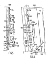
- the drawer 100 has a groove 110 with a step 111.
- a contact plate 109 is secured in the groove 110 and co-operates with a wiper contact 107 attached to the lower end region of a coin chute 108 that is inclined to the vertical.
- An elongated slot 114 is formed in the chute 108.
- two top contact assemblies 115 and 115a capable of pivoting about parallel axes X-X, X'-X' relative to a block 117 clamped in the slot 114 by a respective clamping screw 118. They are electrically in series.
- the two contact assemblies 115 and 115a are essentially identical, so it will be sufficient to describe one, 115, only.
- the assembly has a metal plate flap 130 carrying a pair of aligned screws 116, 132.
- the screw 116 is in a lower plane as viewed, and its curved surface (or at least the bottom portion thereof) is provided with an insulated covering or coating 134. Its plane end face 136 will remain as bare metal so that only this end face 136 can make electrical contact with the coins to complete a circuit.
- the other screw 132 carries at its end a knob 138 of insulating material.
- the bottom surface of the knob 138 is partly chamfered at 140 so that it tapers to a tip 142 on the side nearer the screw 116.
- the screw 132 with the tip 142 is slightly longer than the screw 116.
- the operation of this embodiment is essentially similar to that described previously and only the differences will be highlighted.
- the mechanism can be actuated by one high-value coin (such as the newly announced U.K. £1 coin) or by an equal-value combination of two or more coins.
- the high-value coin (again, such as the U.K. £1 coin) is of relatively small diameter, the step 111 in the groove 110 will ensure that it comes to rest in the desired plane and does not, for instance, roll too far to the right, as viewed in Figure 4.
- the contact assemblies 115, 115a When a coin is inserted into the chute 108 the contact assemblies 115, 115a are pivoted about the axes X-X, X'-X', as before.
- the screw 132 with the insulating knob 138 and chamfered surface 140 will be pushed up by the coins and serves to hold the contact screw 116 out of contact with the coins, unless the coins are "right".
- the coating or covering 134 it is ensured that electrical contact is made only when a correct coin is directly under the end face 136, thereby preventing fraud e.g. by jogging the drawer or rocking the whole vending cabinet in an attempt to make coin edge-to-screw contact.
- the contact assembly 115a has a fine adjustment mechanism for its position.
- the block 117 is slidably mounted in the slot 114 and carries a bracket 150 formed with a threaded aperture in which engages one end of a fine adjustment screw 152 extending from a bracket 154 fixed to the chute 108.
- the other end of the screw 152 has a head 156 which can be turned by a screwdriver to raise or lower the bracket 150 and so the assembly 115a
- the mechanism is designed to dispense on (i) one £ win, or (ii) two 50p coins, but a) one 10p or 50p or other current U.K. coin would not have the right diameter or thickness to disable the insulating knob, or b) one 50p and one 10p coin are of insufficient length and the screws 116, 132 would be above them in the chute and engage the back panel 12 or c) one 50p and two 10p coins would be of sufficient length but the wrong thickness and so the chamfered surface 140 would hold the surface 136 of screw 116 away from the third coin.
Landscapes
- Physics & Mathematics (AREA)
- General Physics & Mathematics (AREA)
- Control Of Vending Devices And Auxiliary Devices For Vending Devices (AREA)
- Vending Machines For Individual Products (AREA)
Applications Claiming Priority (2)
| Application Number | Priority Date | Filing Date | Title |
|---|---|---|---|
| GB8028197 | 1980-09-01 | ||
| GB8028197 | 1980-09-01 |
Publications (2)
| Publication Number | Publication Date |
|---|---|
| EP0047172A1 true EP0047172A1 (fr) | 1982-03-10 |
| EP0047172B1 EP0047172B1 (fr) | 1986-07-16 |
Family
ID=10515771
Family Applications (1)
| Application Number | Title | Priority Date | Filing Date |
|---|---|---|---|
| EP19810303993 Expired EP0047172B1 (fr) | 1980-09-01 | 1981-09-01 | Dispositif de déblocage et leur distribution automatique de denrées actionné par pièces de monnaie |
Country Status (4)
| Country | Link |
|---|---|
| EP (1) | EP0047172B1 (fr) |
| DE (1) | DE3174932D1 (fr) |
| IE (1) | IE52847B1 (fr) |
| WO (1) | WO1982000909A1 (fr) |
Cited By (3)
| Publication number | Priority date | Publication date | Assignee | Title |
|---|---|---|---|---|
| GB2166897A (en) * | 1984-09-25 | 1986-05-14 | Terence Thomas Ketteringham | Coin freed vending machine |
| DE3513326A1 (de) * | 1985-04-13 | 1986-10-23 | National Rejectors Inc. Gmbh, 2150 Buxtehude | Muenzpruefer |
| GB2181877A (en) * | 1985-09-16 | 1987-04-29 | Electronic Rentals Group Plc | Coin operated switch |
Citations (7)
| Publication number | Priority date | Publication date | Assignee | Title |
|---|---|---|---|---|
| BE426637A (fr) * | ||||
| US1498548A (en) * | 1917-10-23 | 1924-06-24 | James W Hughes | Coin-controlled lock for vending devices |
| CH225073A (fr) * | 1938-06-28 | 1942-12-31 | Valoris S A | Dispositif de commande d'un distributeur automatique actionné électriquement. |
| GB586269A (en) * | 1939-01-09 | 1947-03-13 | Johannes Petersen | Improvements in coin-freed vending machines |
| DE905685C (de) * | 1951-10-18 | 1954-03-04 | Heinrich H Kluessendorf Fa | Elektrisch angetriebener Selbstverkaeufer |
| FR1460027A (fr) * | 1965-10-14 | 1966-06-17 | S E F M A | Dispositif de commande pour distributeur automatique |
| DE2718656A1 (de) * | 1977-04-27 | 1978-11-02 | Hans Hermann Trautwein | Automat zur ausgabe von waren |
-
1981
- 1981-08-31 IE IE198981A patent/IE52847B1/en unknown
- 1981-09-01 EP EP19810303993 patent/EP0047172B1/fr not_active Expired
- 1981-09-01 WO PCT/GB1981/000175 patent/WO1982000909A1/fr not_active Ceased
- 1981-09-01 DE DE8181303993T patent/DE3174932D1/de not_active Expired
Patent Citations (7)
| Publication number | Priority date | Publication date | Assignee | Title |
|---|---|---|---|---|
| BE426637A (fr) * | ||||
| US1498548A (en) * | 1917-10-23 | 1924-06-24 | James W Hughes | Coin-controlled lock for vending devices |
| CH225073A (fr) * | 1938-06-28 | 1942-12-31 | Valoris S A | Dispositif de commande d'un distributeur automatique actionné électriquement. |
| GB586269A (en) * | 1939-01-09 | 1947-03-13 | Johannes Petersen | Improvements in coin-freed vending machines |
| DE905685C (de) * | 1951-10-18 | 1954-03-04 | Heinrich H Kluessendorf Fa | Elektrisch angetriebener Selbstverkaeufer |
| FR1460027A (fr) * | 1965-10-14 | 1966-06-17 | S E F M A | Dispositif de commande pour distributeur automatique |
| DE2718656A1 (de) * | 1977-04-27 | 1978-11-02 | Hans Hermann Trautwein | Automat zur ausgabe von waren |
Cited By (3)
| Publication number | Priority date | Publication date | Assignee | Title |
|---|---|---|---|---|
| GB2166897A (en) * | 1984-09-25 | 1986-05-14 | Terence Thomas Ketteringham | Coin freed vending machine |
| DE3513326A1 (de) * | 1985-04-13 | 1986-10-23 | National Rejectors Inc. Gmbh, 2150 Buxtehude | Muenzpruefer |
| GB2181877A (en) * | 1985-09-16 | 1987-04-29 | Electronic Rentals Group Plc | Coin operated switch |
Also Published As
| Publication number | Publication date |
|---|---|
| IE52847B1 (en) | 1988-03-30 |
| IE811989L (en) | 1982-03-01 |
| DE3174932D1 (en) | 1986-08-21 |
| WO1982000909A1 (fr) | 1982-03-18 |
| EP0047172B1 (fr) | 1986-07-16 |
Similar Documents
| Publication | Publication Date | Title |
|---|---|---|
| US4538719A (en) | Electronic coin acceptor | |
| US3844297A (en) | Coin selector and sorter | |
| US5042635A (en) | Rapid coin acceptor | |
| US3783989A (en) | Escrow and security device for coin and dollar bill operated vending machine | |
| US4570779A (en) | Coin sorting device | |
| US2954111A (en) | Returned bottle detector | |
| EP0047172B1 (fr) | Dispositif de déblocage et leur distribution automatique de denrées actionné par pièces de monnaie | |
| US2567900A (en) | Coin-changer mechanism | |
| US6637578B1 (en) | Coin processing device | |
| US2230566A (en) | Coin-selecting mechanism | |
| US4386691A (en) | Electromechanical coin-operated latch mechanism | |
| US5526918A (en) | Coin validating apparatus and method | |
| US4220234A (en) | Supplemental coin acceptor/rejector mechanism for coin operated machines | |
| US2770343A (en) | Coin tester | |
| US3403765A (en) | Coin-operated dispensing mechanism | |
| US4987989A (en) | Coin-freed vending machine mechanism | |
| US2669336A (en) | Coin controlled mechanism | |
| US1498548A (en) | Coin-controlled lock for vending devices | |
| US3361241A (en) | Multiple-coin controlled coin slide | |
| US5402871A (en) | Drop coin mechanism | |
| US3337125A (en) | Coin escrow device | |
| US6656034B2 (en) | Coin handling device with folding escalator | |
| US3696905A (en) | Coin escrow means and circuit | |
| US2371260A (en) | Coin-actuated device | |
| US3782518A (en) | Coin controlled vending apparatus |
Legal Events
| Date | Code | Title | Description |
|---|---|---|---|
| PUAI | Public reference made under article 153(3) epc to a published international application that has entered the european phase |
Free format text: ORIGINAL CODE: 0009012 |
|
| AK | Designated contracting states |
Designated state(s): BE DE FR GB IT NL SE |
|
| 17P | Request for examination filed |
Effective date: 19820901 |
|
| RIN1 | Information on inventor provided before grant (corrected) |
Inventor name: RATZKER, HERMAN BERTHOLD |
|
| RAP1 | Party data changed (applicant data changed or rights of an application transferred) |
Owner name: PRECISION VENDING MACHINES LIMITED |
|
| GRAA | (expected) grant |
Free format text: ORIGINAL CODE: 0009210 |
|
| AK | Designated contracting states |
Kind code of ref document: B1 Designated state(s): BE DE FR GB IT NL SE |
|
| PG25 | Lapsed in a contracting state [announced via postgrant information from national office to epo] |
Ref country code: NL Effective date: 19860716 Ref country code: IT Free format text: LAPSE BECAUSE OF FAILURE TO SUBMIT A TRANSLATION OF THE DESCRIPTION OR TO PAY THE FEE WITHIN THE PRESCRIBED TIME-LIMIT;WARNING: LAPSES OF ITALIAN PATENTS WITH EFFECTIVE DATE BEFORE 2007 MAY HAVE OCCURRED AT ANY TIME BEFORE 2007. THE CORRECT EFFECTIVE DATE MAY BE DIFFERENT FROM THE ONE RECORDED. Effective date: 19860716 Ref country code: BE Effective date: 19860716 |
|
| PG25 | Lapsed in a contracting state [announced via postgrant information from national office to epo] |
Ref country code: SE Effective date: 19860731 |
|
| REF | Corresponds to: |
Ref document number: 3174932 Country of ref document: DE Date of ref document: 19860821 |
|
| ET | Fr: translation filed | ||
| NLV1 | Nl: lapsed or annulled due to failure to fulfill the requirements of art. 29p and 29m of the patents act | ||
| PLBE | No opposition filed within time limit |
Free format text: ORIGINAL CODE: 0009261 |
|
| STAA | Information on the status of an ep patent application or granted ep patent |
Free format text: STATUS: NO OPPOSITION FILED WITHIN TIME LIMIT |
|
| 26N | No opposition filed | ||
| PG25 | Lapsed in a contracting state [announced via postgrant information from national office to epo] |
Ref country code: FR Effective date: 19900531 |
|
| PG25 | Lapsed in a contracting state [announced via postgrant information from national office to epo] |
Ref country code: DE Effective date: 19900601 |
|
| REG | Reference to a national code |
Ref country code: FR Ref legal event code: ST |
|
| PGFP | Annual fee paid to national office [announced via postgrant information from national office to epo] |
Ref country code: GB Payment date: 19900831 Year of fee payment: 10 |
|
| PG25 | Lapsed in a contracting state [announced via postgrant information from national office to epo] |
Ref country code: GB Effective date: 19910901 |
|
| GBPC | Gb: european patent ceased through non-payment of renewal fee |