EP0047352A1 - Behandlungsvorrichtung für ein Fluidum, wie Filter, Schmierapparate und Behälter dafür - Google Patents
Behandlungsvorrichtung für ein Fluidum, wie Filter, Schmierapparate und Behälter dafür Download PDFInfo
- Publication number
- EP0047352A1 EP0047352A1 EP80303907A EP80303907A EP0047352A1 EP 0047352 A1 EP0047352 A1 EP 0047352A1 EP 80303907 A EP80303907 A EP 80303907A EP 80303907 A EP80303907 A EP 80303907A EP 0047352 A1 EP0047352 A1 EP 0047352A1
- Authority
- EP
- European Patent Office
- Prior art keywords
- container
- sight glass
- lugs
- recess
- fluid
- Prior art date
- Legal status (The legal status is an assumption and is not a legal conclusion. Google has not performed a legal analysis and makes no representation as to the accuracy of the status listed.)
- Granted
Links
- 239000012530 fluid Substances 0.000 title claims abstract description 25
- 239000011521 glass Substances 0.000 claims abstract description 61
- 238000007789 sealing Methods 0.000 claims description 10
- 239000007788 liquid Substances 0.000 claims description 8
- 230000001419 dependent effect Effects 0.000 claims description 4
- 238000006073 displacement reaction Methods 0.000 claims description 3
- 238000003780 insertion Methods 0.000 claims description 3
- 230000037431 insertion Effects 0.000 claims description 3
- 230000002093 peripheral effect Effects 0.000 claims description 3
- 230000000717 retained effect Effects 0.000 claims 1
- 239000002184 metal Substances 0.000 abstract description 3
- 230000000295 complement effect Effects 0.000 abstract description 2
- 239000000463 material Substances 0.000 description 3
- 239000002131 composite material Substances 0.000 description 2
- 230000006835 compression Effects 0.000 description 2
- 238000007906 compression Methods 0.000 description 2
- 238000010276 construction Methods 0.000 description 2
- 230000008878 coupling Effects 0.000 description 2
- 238000010168 coupling process Methods 0.000 description 2
- 238000005859 coupling reaction Methods 0.000 description 2
- 238000004891 communication Methods 0.000 description 1
- 238000004512 die casting Methods 0.000 description 1
- 230000000694 effects Effects 0.000 description 1
- 238000001914 filtration Methods 0.000 description 1
- 230000005484 gravity Effects 0.000 description 1
- 239000012535 impurity Substances 0.000 description 1
- 238000009434 installation Methods 0.000 description 1
- 239000010687 lubricating oil Substances 0.000 description 1
- 239000004033 plastic Substances 0.000 description 1
- 229920003023 plastic Polymers 0.000 description 1
- 239000004417 polycarbonate Substances 0.000 description 1
- 229920000515 polycarbonate Polymers 0.000 description 1
- 238000000926 separation method Methods 0.000 description 1
- 239000012780 transparent material Substances 0.000 description 1
Images
Classifications
-
- F—MECHANICAL ENGINEERING; LIGHTING; HEATING; WEAPONS; BLASTING
- F16—ENGINEERING ELEMENTS AND UNITS; GENERAL MEASURES FOR PRODUCING AND MAINTAINING EFFECTIVE FUNCTIONING OF MACHINES OR INSTALLATIONS; THERMAL INSULATION IN GENERAL
- F16N—LUBRICATING
- F16N7/00—Arrangements for supplying oil or unspecified lubricant from a stationary reservoir or the equivalent in or on the machine or member to be lubricated
- F16N7/30—Arrangements for supplying oil or unspecified lubricant from a stationary reservoir or the equivalent in or on the machine or member to be lubricated the oil being fed or carried along by another fluid
- F16N7/32—Mist lubrication
- F16N7/34—Atomising devices for oil
-
- F—MECHANICAL ENGINEERING; LIGHTING; HEATING; WEAPONS; BLASTING
- F16—ENGINEERING ELEMENTS AND UNITS; GENERAL MEASURES FOR PRODUCING AND MAINTAINING EFFECTIVE FUNCTIONING OF MACHINES OR INSTALLATIONS; THERMAL INSULATION IN GENERAL
- F16N—LUBRICATING
- F16N19/00—Lubricant containers for use in lubricators or lubrication systems
- F16N19/003—Indicating oil level
-
- G—PHYSICS
- G01—MEASURING; TESTING
- G01F—MEASURING VOLUME, VOLUME FLOW, MASS FLOW OR LIQUID LEVEL; METERING BY VOLUME
- G01F23/00—Indicating or measuring liquid level or level of fluent solid material, e.g. indicating in terms of volume or indicating by means of an alarm
- G01F23/02—Indicating or measuring liquid level or level of fluent solid material, e.g. indicating in terms of volume or indicating by means of an alarm by gauge glasses or other apparatus involving a window or transparent tube for directly observing the level to be measured or the level of a liquid column in free communication with the main body of the liquid
Definitions
- This invention relates to fluid flow devices including fluid filters and lubricators of the kind comprising a dependent liquid container.
- a filter this container will serve as a collecting bowl in which the liquid separated from a throughflow is deposited to be drained off, as the separation of liquid from a pressure air supply.
- a lubricator the container will provide a reservoir of liquid lubricant to be taken up by a pressure gas throughflow.
- a fluid container provided with a sight glass for indicating the fluid level therein, said sight glass being provided by an elongate light-transmitting member of tapered form slidable into and sealingly fitting a tapered slot or recess in a side of the container.
- a sealing ring may be interposed between the sight glass and the adjoining surface of the container to encompass a wall area of the container containing at least one communicating opening in said wall to the container interior at regions adjacent both the top and the bottom of said sight glass member.
- the sight glass member is insertable in said slot from the top and means are arranged to be disposed above said member to limit or prevent upwards displacement of the member.
- Stop means may be provided at one end of the slot or recess to limit the insertion of the sight glass member therein, and this can be conveniently achieved with a slot or recess comprising a U-form flange, the bottom of which provides said stop means.
- a fluid handling device such as a filter or lubricator, comprising a liquid container dependent from a body member of the device, the container having a cylindrical upper rim with a group of at least two peripherally spaced lugs for engagement with a group of at least two spaced lugs adjacent an opening of the body member to attach the container to the body member with the container supported by the location of its lugs over those of the body member, a plurality of stop elements projecting vertically (that is to say, upwardly or downwardly) from one or more of the lugs for co-operation with the lug or lugs engaging therewith when the container and body member are attached together, there being at least two peripherally spaced elements that project to different levels and the respective groups of lugs being locatable during assembly at relative heights that allow the lugs of one group to pass the smaller element or elements when there is relative rotation between the container and body member in one direction, the larger element or elements acting as abutting stop means limiting said
- the lugs form equispaced series providing a number of discrete alternative angular orientations of the container on the body member so as to allow a choice to be made for any particular installation.
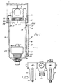
- the filter comprises a die-cast body 2 provided with inlet and outlet ports 4,6 that communicate with a conventional filtration arrangement (not shown for the sake of clarity) attached to screwed boss 8 of the body and disposed within a dependent bowl 10 detachably held in the head by a quick-release locking arrangement to be described in detail below.
- the bowl itself comprises a metal die-casting in which there is mounted a sight glass 12 showing the liquid level within the bowl, and an automatic dump valve 14 for draining the bowl.
- the bowl generally has a cylindrical form, tapering slightly downwardly.
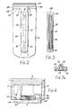
- a flat wall portion 16 is formed extending from the top of the bowl nearly to its bottom and an integrally formed L-section flange 18 standing proud of this wall portion extends around its bottom region and along its lateral edges to a level close to the top of the bowl.
- the two main lengths of the flange at the opposite lateral edges of the flat wall portion define an elongate slot or recess 24, closed at the bottom by the lowermost portion of the flange.
- the two main lengths of the flange diverge slightly in the upward direction as can be seen in Fig. 2.
- the flange comprises an outer lip 20 having a planar outer face radially of the bowl but tapering in thickness towards its upper end as can be seen from the broken line 20a indicating its inner face, and at a slightly diverging spacing from the flat wall portion 16 in this same upward direction, as can also be seen in Fig. 1.
- the lip 20 thus forms a channel-like margin to the borders of the U-form recess 24 between the flange outer lip and the flat wall portion, the height of which recess radially of the bowl increases with the divergence of the flange lip from the wall portion 16, while the width of the U-form recess 24 similarly increases with distance from the bottom of the bowl, due to the divergence of the upwardly extending main lengths of the flange.
- the channeled recess 24 is used to secure the sight glass 12 of moulded glass or other transparent or translucent material, an integral lip 26 extending around the side and bottom edges of the sight glass having a form complementary to that of the channel-like margin of the recess fitting under the flange outer lip 20.
- the sight glass includes a thickened top portion 28, the rear face of which is coplanar with the rear face of the lip 26, and a ridged central portion 30 between the laterally opposite portions of the lip 26 that has its outer face substantially flush with the outer face of the flange lip 20.
- the sight glass thus defines a trough-like internal space 32 closed at the rear or radially inner face by the flat 16 wall portion of the bowl. Within the space 32 there can be provided a float element 33 that can move freely up and down the sight glass to indicate the liquid level in the space.
- An 0-ring 34 is seated in a recess 36 in the rear face of the lip 26 and top portion 28 of the sight glass to seal the space 32, and spaced apertures 38, 40 in the wall portion 16 adjacent to the top and bottom of the space communicate with the main interior space of the bowl.
- the 0-ring can be a standard circular-form ring that is pulled into the elongate shape required to match the recess 36, but that then fits the recess without being under tension.
- the sight glass can be easily slid into the recess from the top with an initial radial and lateral play or clearance.
- the radial play has been taken up and the 0-ring 34 begins to be urged against the flat.
- the compression force on it increases with continued movement so that it is in an operative state for effective sealing as the sight glass is pushed further down.
- the top of the sight glass is immediately below and only slightly spaced from the bottom rim 44 of the body. If there should be any tendency of the sight glass to lift in use, e.g. due to a combination of internal fluid pressure forces and vibration, it is only able to move to a very limited extent before it abuts against the rim. This ensures that the 0-ring will remain securely engaged between the sight glass and the bowl flat wall portion to act as an effective seal, and also that both apertures 38, 40 remain in communication with the sight glass internal space 32 so that false readings will not be obtained.
- the bowl is held in the body by two interengaging series of oblong lugs 48, 50, that are respectively on the bowl outer periphery adjacent its top rim 54 and on the inner face of cylindrical bottom lip of the body.
- the bowl top rim carries an 0-ring 52 that is urged against an inner peripheral sealing face 56 within the body when the bowl lugs and the body lugs are engaged, as shown in Fig. 1.
- the cylindrical sealing face is preceded by a tapered lead-in face 58 below it to guide the sealing ring into place.
- the flat wall portion 16 of the bowl is located in the spacing between two adjacent lugs 48.
- the lugs 48 on the bowl have flat bottom faces 62 of the same length as the top faces 64 of those on the head, but they extend vertically beyond those flat bottom faces with terminal portions that comprise projections 66, 68 depending below the bottom faces.
- the projections 66 at the right-hand end (as seen in Fig. 2) of each lug, the leading end, are shorter than the projections 68 at the other end, the trailing end.
- the outer dimension of the bowl lugs radially of the bowl is greater than the inner radius of the internal shoulder ⁇ 70 at the top of the body bottom lip.
- the bowl rim can therefore be inserted upwardly into the body, its lugs 48 passing between the body lugs 50, until they abut against the shoulder 70.
- the bottom surfaces 62 of the bowl lugs are at a higher level than the top surfaces 64 of the body lugs. This is also the case with the shorter, leading end projections 66, but the longer projections 68 still depend below the level of these top surfaces 64.
- the longer projections 68 therefore prevent rotation of the inserted bowl anticlockwise, but it can be rotated clockwise, the shorter projections 66 passing over the body lugs until the individual lugs of the two series are located one directly over the other. At that stage further clockwise rotation is prevented by abutment of the longer projections 68 with the body lugs.
- each bowl lug 48 If released in this position, the bowl will move downwards to rest upon the body lugs, due to gravity and the resilience of the 0-ring 54.
- the projections 66, 68 of each bowl lug 48 then lie one at each end of the associated body lug 50 as shown in Fig. 1, so that both series of projections will prevent rotation of the bowl from its fully engaged position with the body.
- the angular orientation of bowl on the body, with the sight glass 12 on a face normal to the axes of the ports 4,6 is determined by the lugs 48, 50, and with four equispaced lugs in each series the bowl can be assembled on the body in any of four alternative angular orientations at 900 intervals. Other alternatives are possible with different numbers of lugs.
- the shorter projections can be so disposed as to engage a recess intermediate the length of their co-operating lugs when the bowl is engaged with the body, and in that case the shorter and longer projections can be disposed one on each of a pair of co-operating bowl and body lugs.
- Fig. 4 of the drawings also illustrates wedge-form recesses 74, 76 on the body end faces into which the filter inlet and outlet conduits open. These are part of the coupling means for connecting the filter into a pipeline as described in more detail in our co-pending application filed simultaneously herewith.
- a pressure air lubricator as is schematically shown in Fig. 5 in a composite assembly for a pressure air supply line, comprising a filter 82, pressure regulator 84 and lubricator 86.
- the bowls 88 of the filter and lubricator each have sight glasses of the form described above and are interengaged with the bodies of the filter and lubricator respectively by the locking lugs described above.
- the filter 82 differs from that described earlier in that it has a manual drain valve 90.
- the assembly in Fig. 5 includes coupling means of the form described in our co-pending application referred to above.
Landscapes
- Engineering & Computer Science (AREA)
- General Engineering & Computer Science (AREA)
- Mechanical Engineering (AREA)
- Chemical & Material Sciences (AREA)
- General Physics & Mathematics (AREA)
- Combustion & Propulsion (AREA)
- Oil, Petroleum & Natural Gas (AREA)
- Fluid Mechanics (AREA)
- Physics & Mathematics (AREA)
- Closures For Containers (AREA)
- Filtering Of Dispersed Particles In Gases (AREA)
- Filtering Materials (AREA)
- Level Indicators Using A Float (AREA)
- Investigating Or Analysing Materials By Optical Means (AREA)
- Manipulator (AREA)
- Organic Low-Molecular-Weight Compounds And Preparation Thereof (AREA)
- Fats And Perfumes (AREA)
- Medical Preparation Storing Or Oral Administration Devices (AREA)
Priority Applications (1)
| Application Number | Priority Date | Filing Date | Title |
|---|---|---|---|
| AT80303907T ATE12139T1 (de) | 1980-09-05 | 1980-11-03 | Behandlungsvorrichtung fuer ein fluidum, wie filter, schmierapparate und behaelter dafuer. |
Applications Claiming Priority (2)
| Application Number | Priority Date | Filing Date | Title |
|---|---|---|---|
| GB8028833 | 1980-09-05 | ||
| GB8028833 | 1980-09-05 |
Publications (2)
| Publication Number | Publication Date |
|---|---|
| EP0047352A1 true EP0047352A1 (de) | 1982-03-17 |
| EP0047352B1 EP0047352B1 (de) | 1985-03-13 |
Family
ID=10515899
Family Applications (1)
| Application Number | Title | Priority Date | Filing Date |
|---|---|---|---|
| EP80303907A Expired EP0047352B1 (de) | 1980-09-05 | 1980-11-03 | Behandlungsvorrichtung für ein Fluidum, wie Filter, Schmierapparate und Behälter dafür |
Country Status (8)
| Country | Link |
|---|---|
| US (1) | US4446731A (de) |
| EP (1) | EP0047352B1 (de) |
| JP (2) | JPS5775111A (de) |
| AT (1) | ATE12139T1 (de) |
| AU (2) | AU7472781A (de) |
| CA (1) | CA1166975A (de) |
| DE (1) | DE3070281D1 (de) |
| ZA (2) | ZA815845B (de) |
Cited By (4)
| Publication number | Priority date | Publication date | Assignee | Title |
|---|---|---|---|---|
| EP0091803A1 (de) * | 1982-04-13 | 1983-10-19 | Watts Fluid Power Limited | Behälter für Druckluftanlage |
| EP0184197A1 (de) * | 1984-12-05 | 1986-06-11 | Bayerische Motoren Werke Aktiengesellschaft, Patentabteilung AJ-3 | Kunststoff-Wasserkasten für Querstrom-Kühler von Brennkraftmaschinen |
| EP0625695A1 (de) * | 1993-05-15 | 1994-11-23 | Norgren Martonair Limited | Verbesserungen von Schaugläsern |
| DE29902944U1 (de) * | 1999-02-19 | 2000-07-13 | Pressol Schmiergeräte GmbH, 90427 Nürnberg | Druckluftmotor für eine Schmierstoffpumpe |
Families Citing this family (5)
| Publication number | Priority date | Publication date | Assignee | Title |
|---|---|---|---|---|
| US5389246A (en) * | 1993-01-21 | 1995-02-14 | Zinga Industries Inc. | Reservoir filter |
| US6499439B1 (en) | 2001-06-15 | 2002-12-31 | Triad Metal Products Company | Modular stamped sight glass assembly |
| US6771366B2 (en) * | 2002-10-04 | 2004-08-03 | J.M. Canty Inc. | Fluid flow cell |
| US7066218B1 (en) * | 2003-10-29 | 2006-06-27 | Tmc Systems, L.P. | Insect control system and method |
| EP2761259A1 (de) | 2011-09-26 | 2014-08-06 | Saudi Arabian Oil Company | Drainierbares schauglass und zugehörige verfahren |
Citations (6)
| Publication number | Priority date | Publication date | Assignee | Title |
|---|---|---|---|---|
| FR329860A (fr) * | 1903-03-02 | 1903-08-06 | John Howard Johnston | Perfectionnements aux graisseurs à pression hydraulique |
| GB141781A (en) * | 1918-12-23 | 1920-04-23 | William Burwell | Improvements relating to glazing or securing glass in objects and structures |
| US1339561A (en) * | 1919-06-21 | 1920-05-11 | Hulett Elzie Henry | Water-glass |
| US2609692A (en) * | 1949-07-15 | 1952-09-09 | Erick L Ahlgren | Fluid content gauge for lighters |
| US2672757A (en) * | 1951-06-26 | 1954-03-23 | Buffalo Elipse Corp | Liquid-level gauge |
| FR1418956A (fr) * | 1964-10-13 | 1965-11-26 | J Laffort & Cie Soc | Récipient pour le dosage précis de fluides liquéfiés |
Family Cites Families (3)
| Publication number | Priority date | Publication date | Assignee | Title |
|---|---|---|---|---|
| DE230185C (de) * | ||||
| GB191206443A (en) * | 1912-03-15 | 1912-06-13 | Charles Arthur Allison | Liquid-level Indicators. |
| US1063604A (en) * | 1912-04-22 | 1913-06-03 | Michael F Scalley | Water-gage for steam-boilers. |
-
1980
- 1980-11-03 EP EP80303907A patent/EP0047352B1/de not_active Expired
- 1980-11-03 DE DE8080303907T patent/DE3070281D1/de not_active Expired
- 1980-11-03 AT AT80303907T patent/ATE12139T1/de not_active IP Right Cessation
-
1981
- 1981-08-24 ZA ZA815845A patent/ZA815845B/xx unknown
- 1981-08-24 ZA ZA815844A patent/ZA815844B/xx unknown
- 1981-08-28 AU AU74727/81A patent/AU7472781A/en not_active Abandoned
- 1981-08-28 AU AU74728/81A patent/AU543587B2/en not_active Ceased
- 1981-09-04 JP JP56138679A patent/JPS5775111A/ja active Pending
- 1981-09-04 US US06/299,411 patent/US4446731A/en not_active Expired - Fee Related
- 1981-09-04 JP JP56138680A patent/JPS5775112A/ja active Pending
- 1981-09-04 CA CA000385226A patent/CA1166975A/en not_active Expired
Patent Citations (6)
| Publication number | Priority date | Publication date | Assignee | Title |
|---|---|---|---|---|
| FR329860A (fr) * | 1903-03-02 | 1903-08-06 | John Howard Johnston | Perfectionnements aux graisseurs à pression hydraulique |
| GB141781A (en) * | 1918-12-23 | 1920-04-23 | William Burwell | Improvements relating to glazing or securing glass in objects and structures |
| US1339561A (en) * | 1919-06-21 | 1920-05-11 | Hulett Elzie Henry | Water-glass |
| US2609692A (en) * | 1949-07-15 | 1952-09-09 | Erick L Ahlgren | Fluid content gauge for lighters |
| US2672757A (en) * | 1951-06-26 | 1954-03-23 | Buffalo Elipse Corp | Liquid-level gauge |
| FR1418956A (fr) * | 1964-10-13 | 1965-11-26 | J Laffort & Cie Soc | Récipient pour le dosage précis de fluides liquéfiés |
Non-Patent Citations (1)
| Title |
|---|
| MACHINE DESIGN, vol. 33, 25th May, 1961, page 202, Penton Inc. Cleveland "Filter Reservoir" * |
Cited By (6)
| Publication number | Priority date | Publication date | Assignee | Title |
|---|---|---|---|---|
| EP0091803A1 (de) * | 1982-04-13 | 1983-10-19 | Watts Fluid Power Limited | Behälter für Druckluftanlage |
| EP0184197A1 (de) * | 1984-12-05 | 1986-06-11 | Bayerische Motoren Werke Aktiengesellschaft, Patentabteilung AJ-3 | Kunststoff-Wasserkasten für Querstrom-Kühler von Brennkraftmaschinen |
| WO1986003555A1 (fr) * | 1984-12-05 | 1986-06-19 | Bayerische Motoren Werke Aktiengesellschaft | Radiateur en matiere plastique pour les systemes de refroidissement a ecoulement transversal des moteurs a combustion interne |
| US4823862A (en) * | 1984-12-05 | 1989-04-25 | Bayerische Motoren Werke Aktiengesellschaft | Plastic radiator for transverse-flow cooling systems of internal combustion engines |
| EP0625695A1 (de) * | 1993-05-15 | 1994-11-23 | Norgren Martonair Limited | Verbesserungen von Schaugläsern |
| DE29902944U1 (de) * | 1999-02-19 | 2000-07-13 | Pressol Schmiergeräte GmbH, 90427 Nürnberg | Druckluftmotor für eine Schmierstoffpumpe |
Also Published As
| Publication number | Publication date |
|---|---|
| ZA815844B (en) | 1982-08-25 |
| CA1166975A (en) | 1984-05-08 |
| ZA815845B (en) | 1982-08-25 |
| ATE12139T1 (de) | 1985-03-15 |
| EP0047352B1 (de) | 1985-03-13 |
| AU543587B2 (en) | 1985-04-26 |
| US4446731A (en) | 1984-05-08 |
| JPS5775112A (en) | 1982-05-11 |
| AU7472781A (en) | 1982-03-11 |
| JPS5775111A (en) | 1982-05-11 |
| AU7472881A (en) | 1982-03-11 |
| DE3070281D1 (en) | 1985-04-18 |
Similar Documents
| Publication | Publication Date | Title |
|---|---|---|
| US4725354A (en) | Filtering system | |
| US5766463A (en) | Fuel filter cartridge | |
| USRE34050E (en) | Filtering system | |
| US5762671A (en) | Multi-size threaded adapter | |
| EP2598742B1 (de) | Filterdurchlaufanordnung mit entlüftung | |
| EP0223569B1 (de) | Filtersystem | |
| US5114572A (en) | Filter assembly and cartridge therefor | |
| CN102256679B (zh) | 具有在过滤元件的端板上的连接结构的流体过滤器 | |
| EP0047352B1 (de) | Behandlungsvorrichtung für ein Fluidum, wie Filter, Schmierapparate und Behälter dafür | |
| EP0937868A1 (de) | Ölfilterbefestigungstruktur | |
| US9586163B2 (en) | Filter assembly with modular relief valve interface | |
| JPH0450844B2 (de) | ||
| US4640771A (en) | Fluid intake screening device | |
| US20020125178A1 (en) | Fluid filter with pressure relief valve | |
| JPH08508201A (ja) | 流体の還流フィルタ | |
| EP0059558A1 (de) | Unterdruckventil für sanitäre Anlagen | |
| EP0198454B1 (de) | Gehäusebefestigungsvorrichtung | |
| US4297212A (en) | Oil filter unit | |
| EP3551314A1 (de) | Kraftstofffilter mit wassersammelschale | |
| JPH03157110A (ja) | オイルストレーナ装置 | |
| JP7308347B2 (ja) | 自動車用フルードフィルターおよびフルードフィルター用フィルターカートリッジ | |
| US4367144A (en) | Fluid strainer or filter | |
| AU2006316594B2 (en) | Fuel filter cartridge apparatus | |
| US1579205A (en) | Oil strainer | |
| US4079744A (en) | Drain valve |
Legal Events
| Date | Code | Title | Description |
|---|---|---|---|
| PUAI | Public reference made under article 153(3) epc to a published international application that has entered the european phase |
Free format text: ORIGINAL CODE: 0009012 |
|
| AK | Designated contracting states |
Designated state(s): AT BE CH DE FR GB IT LU NL SE |
|
| 17P | Request for examination filed |
Effective date: 19820730 |
|
| ITF | It: translation for a ep patent filed | ||
| GRAA | (expected) grant |
Free format text: ORIGINAL CODE: 0009210 |
|
| AK | Designated contracting states |
Designated state(s): AT BE CH DE FR GB IT LI LU NL SE |
|
| REF | Corresponds to: |
Ref document number: 12139 Country of ref document: AT Date of ref document: 19850315 Kind code of ref document: T |
|
| REF | Corresponds to: |
Ref document number: 3070281 Country of ref document: DE Date of ref document: 19850418 |
|
| ET | Fr: translation filed | ||
| PGFP | Annual fee paid to national office [announced via postgrant information from national office to epo] |
Ref country code: AT Payment date: 19851023 Year of fee payment: 6 |
|
| PG25 | Lapsed in a contracting state [announced via postgrant information from national office to epo] |
Ref country code: LU Free format text: LAPSE BECAUSE OF NON-PAYMENT OF DUE FEES Effective date: 19851130 |
|
| PGFP | Annual fee paid to national office [announced via postgrant information from national office to epo] |
Ref country code: NL Payment date: 19851130 Year of fee payment: 6 |
|
| PLBE | No opposition filed within time limit |
Free format text: ORIGINAL CODE: 0009261 |
|
| STAA | Information on the status of an ep patent application or granted ep patent |
Free format text: STATUS: NO OPPOSITION FILED WITHIN TIME LIMIT |
|
| 26N | No opposition filed | ||
| PG25 | Lapsed in a contracting state [announced via postgrant information from national office to epo] |
Ref country code: AT Effective date: 19861103 |
|
| PG25 | Lapsed in a contracting state [announced via postgrant information from national office to epo] |
Ref country code: SE Effective date: 19861104 |
|
| PG25 | Lapsed in a contracting state [announced via postgrant information from national office to epo] |
Ref country code: LI Effective date: 19861130 Ref country code: CH Effective date: 19861130 Ref country code: BE Effective date: 19861130 |
|
| BERE | Be: lapsed |
Owner name: SCOVILL INC Effective date: 19861130 |
|
| PG25 | Lapsed in a contracting state [announced via postgrant information from national office to epo] |
Ref country code: NL Effective date: 19870601 |
|
| NLV4 | Nl: lapsed or anulled due to non-payment of the annual fee | ||
| REG | Reference to a national code |
Ref country code: CH Ref legal event code: PL |
|
| PG25 | Lapsed in a contracting state [announced via postgrant information from national office to epo] |
Ref country code: GB Effective date: 19891103 |
|
| GBPC | Gb: european patent ceased through non-payment of renewal fee | ||
| PG25 | Lapsed in a contracting state [announced via postgrant information from national office to epo] |
Ref country code: FR Effective date: 19900731 |
|
| PG25 | Lapsed in a contracting state [announced via postgrant information from national office to epo] |
Ref country code: DE Effective date: 19900801 |
|
| REG | Reference to a national code |
Ref country code: FR Ref legal event code: ST |
|
| EUG | Se: european patent has lapsed |
Ref document number: 80303907.2 Effective date: 19870901 |