EP0047400A2 - Anordnung einer Sattelkupplung auf einer Brückenkonstruktion eines Sattelschleppers - Google Patents
Anordnung einer Sattelkupplung auf einer Brückenkonstruktion eines Sattelschleppers Download PDFInfo
- Publication number
- EP0047400A2 EP0047400A2 EP81106173A EP81106173A EP0047400A2 EP 0047400 A2 EP0047400 A2 EP 0047400A2 EP 81106173 A EP81106173 A EP 81106173A EP 81106173 A EP81106173 A EP 81106173A EP 0047400 A2 EP0047400 A2 EP 0047400A2
- Authority
- EP
- European Patent Office
- Prior art keywords
- profile
- travel
- arrangement according
- profiles
- hat
- Prior art date
- Legal status (The legal status is an assumption and is not a legal conclusion. Google has not performed a legal analysis and makes no representation as to the accuracy of the status listed.)
- Granted
Links
Images
Classifications
-
- B—PERFORMING OPERATIONS; TRANSPORTING
- B62—LAND VEHICLES FOR TRAVELLING OTHERWISE THAN ON RAILS
- B62D—MOTOR VEHICLES; TRAILERS
- B62D53/00—Tractor-trailer combinations; Road trains
- B62D53/04—Tractor-trailer combinations; Road trains comprising a vehicle carrying an essential part of the other vehicle's load by having supporting means for the front or rear part of the other vehicle
- B62D53/08—Fifth wheel traction couplings
- B62D53/0807—Fifth wheel traction couplings adjustable coupling saddles mounted on sub-frames; Mounting plates therefor
Definitions
- the invention relates to an arrangement of a fifth wheel coupling consisting of a fifth wheel and bearing blocks on a bridge construction of a semitrailer tractor, in which the bearing blocks are fastened to the bridge construction with the interposition of a mounting plate, the mounting plate comprising at least one outer wave profile running transversely to the direction of travel and at least one inner one there is a wave profile running transversely to the direction of travel, these wave profiles are fastened with their bases to the bridge structure, the outer wave profile on the top of its apex part serves as a bearing block support and the inner wave profile is attached with the top of its apex part to the underside of the apex part of the outer wave profile.
- the mounting plates serve in particular to bridge height differences of the fifth wheel plate compared to the bridge construction, which are not compensated for by the height of the fifth wheel coupling itself.
- the problem of such a height compensation arises in particular because modern semitrailers are built low with regard to low-build semitrailers, especially for very tall containers. These low-build semitrailers, on the other hand, often have to be used in conjunction with older semitrailers, which for higher building semitrailers have been designed.
- the saddle plates must take on considerable forces, especially in the direction of travel, and must therefore be trained vigorously.
- a mounting plate In a first known construction of a mounting plate, it is designed as a multi-corrugated wave profile, the individual waves being designed as trapezoidal profile waves.
- These known mounting plates have to be relatively heavy in order to be able to absorb the forces occurring on them.
- an inner hat profile is arranged within an outer hat profile, the flanks of the inner hat profile being parallel to the adjacent flanks of the outer hat profile and the bases of the inner and outer hat profiles being fastened independently of one another to the bridge construction.
- This embodiment too can only withstand the loads to be expected during operation if it is carried out with great difficulty.
- the invention has for its object to provide a mounting plate which can be built more easily than the previously known mounting plates thanks to its structural strength.
- At least one of the flanks of the inner wave profile is inclined towards the adjacent flank of the outer wave profile. In this way, the forces acting in the direction of travel are converted into tensile forces, which offer sufficient strength even with light constructions.
- the bases of the outer wave profile and the bases of the inner wave profile lie at least partially one above the other and are fastened together on the bridge structure, for example by means of screw bolts.
- This idea can be realized particularly easily if the bases of the outer wave profile and the inner wave profile are at least partially formed by flanges lying in the horizontal plane.
- a particularly easy to manufacture and yet easily withstand the stresses in operation is that spaced in the direction of travel, two outer hat profiles and at least one inner hat profile are arranged within each of these outer hat profiles.
- the inner hat profiles do not need to go through the entire transverse extent between the bearing blocks; it is rather sufficient if two inner hat profiles are arranged side by side transversely to the direction of travel, one in the area of each bearing block.
- the apex parts of the outer and inner hat profiles are preferably in the area in the direction of travel the front and rear ends of the pedestals, where the fasteners of the pedestals are located, in order to be able to fasten the pedestals with the largest possible fastening base on the mounting plate.
- the inner and the outer corrugated profiles are each formed by individual hat profiles, it proves to be particularly advantageous if the flank remote from the other outer hat profile rises towards the longitudinal center of the bearing blocks from the flanks of an outer hat profile the flank near the other outer hat profile runs essentially perpendicular to the longitudinal center of the bearing blocks. In this way, high compressive strength in the vertical direction is optimally combined with high shear strength in the direction of travel.
- flanks of the inner hat profiles can each form an essentially isosceles trapezoid with their apex part, so that great shear strength is achieved in both longitudinal directions.
- the apex parts of the outer wave profiles can be connected to the apex parts of the inner wave profiles by fastening means, which also serve to fasten the bearing blocks on this apex part, thereby facilitating the fastening work and saving material.
- a bridge construction 10 is symbolized by longitudinal members of the tractor, which can be provided with subframe angles.
- a mounting plate, generally designated 12, is attached to the bridge structure 10.
- the mounting plate 12 is formed by two inner hat profile pairs 14 and 16 lying one behind the other in the direction of travel F according to FIG. 2.
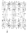
- the hat profiles 14 and 16 of each hat profile pair extend, as can be seen from FIG. 1, transversely to the direction of travel F in each case only over part of the transverse extent of the bridge construction 10.
- the inner hat profiles 14 and 16 have base flanges 14a and 16a, apex parts 14b and 16b and flanks 14c 1 , 14c and 16c, 16c 2 , respectively.
- the outer hat profiles 18 have base flanges 18a and 20a, apex parts 18b and 20b, flanks 18c 1 , 18c 2 b z w. 20c 1 , 20c 2 .
- the base flanges 18a and 20a of the outer hat profiles 18, 20 lie above the base flanges 14a and 16a of the inner hat profiles 14, 16 and are fastened together with these to the bridge structure 10 by fastening bolts 22.
- stops 24 are welded to the bridge structure 10, which are in thrust-transmitting engagement with the ends of the base flanges 14a, 16a and 18a, 20a.
- the apex parts 14b and 16b of the inner hat profiles 14, 16 abut the undersides of the apex parts 18b and 20b of the outer hat profiles 18, 20.
- the bearing blocks 26 of the fifth wheel, generally designated 28, rest on. They are connected to the apex parts 14b, 16b and 18b, 20b by means of bolts 30, so that the apex parts of the inner and outer hat profiles are also connected to one another when the bearing blocks 26 are fastened.
- flanks 14c 1 and 14c 2 of the inner hat profile 14 are inclined relative to the flanks 18c 1 and 18c 2 of the outer hat profile 18.
- This inclination results in a favorable transmission of thrust in the direction of travel F, which translates into tensile and compressive loads on the flanks.
- the vertical edges 18c 2, and 20c 2 of the outer utpro- H file 18 and 20 provide a high stiffness in the vertical direction.
- L-shaped stops 32 for the bearing blocks 26 are attached to the apex parts 18b and 20b of the hat profiles 18, 20 and serve to absorb thrust in the horizontal longitudinal and transverse directions.
- the saddle plate 34 is mounted on the bearing blocks 26 so as to be tiltable about a tilt axis 36.
Landscapes
- Engineering & Computer Science (AREA)
- Chemical & Material Sciences (AREA)
- Combustion & Propulsion (AREA)
- Transportation (AREA)
- Mechanical Engineering (AREA)
- Bridges Or Land Bridges (AREA)
- Handcart (AREA)
- Body Structure For Vehicles (AREA)
- Vehicle Body Suspensions (AREA)
- Connection Of Plates (AREA)
- Vehicle Cleaning, Maintenance, Repair, Refitting, And Outriggers (AREA)
Abstract
Description
- Die Erfindung betrifft eine Anordnung einer aus Sattelplatte und Lagerböcken bestehenden Sattelkupplung auf einer.Brückenkonstruktion eines Sattelschleppers, bei welchen die Lagerböcke auf der Brückenkonstruktion unter Zwischenschaltung einer Montageplatte befestigt sind, wobei die Montageplatte aus mindestens einem äußeren, quer zur Fahrtrichtung verlaufenden Wellenprofil und mindestens einem inneren quer zur Fahrtrichtung verlaufenden Wellenprofil besteht, diese Wellenprofile mit ihren Basen an der Brückenkonstruktion befestigt sind, das äußere Wellenprofil auf der Oberseite seines Scheitelteils als Lagerbockauflager dient und das innere Wellenprofil mit der Oberseite seines Scheitelteils an der Unterseite des Scheitelteils des äußeren Wellenprofils befestigt ist.
- Solche Anordnungen sind bekannt. Die Montageplatten dienen dabei insbesondere zur Überbrückung von Höhendifferenzen der Sattelplatte gegenüber der Brückenkonstruktion, welche durch die Höhe der Sattelkupplung selbst nicht ausgeglichen werden. Das Problem eines solchen Höhenausgleichs stellt sich insbesondere deshalb, weil moderne Sattelschlepper im Hinblick auf niedrig bauende Sattelaufleger, insbesondere für sehr hohe Container, niedrig gebaut werden. Diese niedrig gebauten Sattelschlepper müssen aber andererseits auch häufig in Verbindung mit älteren Sattelauflegern verwendet werden, welche für höher bauende Sattelschlepper konzipiert worden sind.
- Die Sattelplatten müssen erhebliche Kräfte insbesondere in Fahrtrichtung übernehmen und deshalb kräftig ausgebildet werden.
- Bei einer ersten bekannten Konstruktion einer Montageplatte ist diese als ein mehrfach gewelltes Wellenprofil ausgebildet, wobei die einzelnen Wellen als Trapezprofilwellen ausgeführt sind. Diese bekannten Montageplatten müssen verhältnismäßig schwer sein, um die an ihnen auftretenden Kräfte aufnehmen zu können.
- Bei einer weiterhin bekannten Ausführungsform ist innerhalb eines äußeren Hutprofils ein inneres Hutprofil angeordnet, wobei die Flanken des inneren Hutprofils zu den benachbarten Flanken des äußeren Hutprofils jeweils parallel sind und die Basen des inneren und des äußeren Hutprofils unabhängig voneinander an der Brückenkonstruktion befestigt sind. Auch diese Ausführungsform kann den im Betrieb zu erwartenden Belastungen nur standhalten, wenn sie sehr schwer ausgeführt wird.
- Der Erfindung liegt die Aufgabe zugrunde eine Montageplatte anzugeben, welche dank ihrer strukturellen Festigkeit leichter gebaut werden kann als die bisher bekannten Montageplatten.
- Zur Lösung dieser Aufgabe wird erfindungsgemäß vorgeschlagen, daß von den Flanken des inneren Wellenprofils mindestens eine gegen die benachbarte Flanke des äußeren Wellenprofils geneigt ist. Auf diese Weise werden die in Fahrtrichtung wirkenden Kräfte in Zugkräfte umgesetzt, welche auch bei leichten Konstruktionen ausreichende Festigkeit bieten.
- Im Hinblick auf eine Vereinfachung des Aufbaus und eine Vereinfachung der Montage auf der Brückenkonstruktion wird in Weiterbildung der Erfindung vorgeschlagen, daß die Basen des äußeren Wellenprofils und die Basen des inneren Wellenprofils wenigstens teilweise übereinanderliegen und gemeinsam an der Brückenkonstruktion befestigt sind, etwa mittels Schraubbolzen. Dieser Gedanke läßt sich besonders einfach dann realisieren, wenn die Basen des äußeren Wellenprofils und des inneren Wellenprofils wenigstens zum Teil von in horizontaler Ebene liegenden Flanschen gebildet sind.
- Es ist zwar möglich, sowohl das äußere Wellenprofil als auch das innere Wellenprofil über den gesamten Querabstand der Lagerböcke und darüber hinaus zu erstrecken. Es hat sich jedoch gezeigt, daß bei der erfindungsgemäßen Konstruktion die Festigkeit auch dann noch ausreichend ist, wenn sich nur das äußere Wellenprofil quer zur Fahrtrichtung über den vollen Abstand der Lagerböcke und ggf. ein wenig darüber hinaus erstreckt und wenn andererseits im Bereich der Lagerböcke jeweils mindestens ein quer zur Fahrtrichtung kürzeres Wellenprofil angeordnet ist.
- Eine besonders leicht herzustellende und dennoch den Beanspruchungen im Betrieb leicht standhaltende Konstruktion besteht darin, daß in Fahrtrichtung beabstandet, zwei äußere Hutprofile und innerhalb dieser äußeren Hutprofile mindestens jeweils ein inneres Hutprofil angeordnet sind. Was die Anordnung der inneren Hutprofile anbelangt, so brauchen auch diese hier wieder nicht über die ganze Quererstreckung zwischen den Lagerböcken durchzulaufen; es genügt vielmehr, wenn zwei innere Hutprofile quer zur Fahrtrichtung nebeneinander angeordnet sind, jeweils eines im Bereich jedes Lagerbockes.
- Die Scheitelteile der äußeren und der inneren Hutprofile werden vorzugsweise in Fahrtrichtung jeweils im Bereich der vorderen und der hinteren Enden der Lagerböcke angeordnet, wo sich die Befestigungsmittel der Lagerböcke befinden, um die Lagerböcke mit möglichst großer Befestigungsbasis auf der Montageplatte befestigen zu können.
- Bei der bevorzugten Ausführungsform bei der die inneren und die äußeren Wellenprofile jeweils von einzelnen Hutprofilen gebildet sind, erweist es sich als besonders vorteilhaft, wenn von den Flanken eines äußeren Hutprofils jeweils die von dem anderen äußeren Hutprofil fernliegende Flanke zur Längsmitte der Lagerböcke hin ansteigt, während die dem jeweils anderen äußeren Hutprofil naheliegende Flanke im wesentlichen senkrecht zur Längsmitte der Lagerböcke verläuft. Auf diese Weise wird hohe`Druckfestigkeit in vertikaler Richtung mit hoher Schubfestigkeit in Fahrtrichtung optimal kombiniert.
- Die Flanken der inneren Hutprofile können mit deren Scheitelteil jeweils ein im wesentlichen gleichschenkliges Trapez bilden, so daß eine große Schubfestigkeit in beiden Längsrichtungen erzielt wird.
- Die Scheitelteile der äußeren Wellenprofile können mit den Scheitelteilen der inneren Wellenprofile durch Befestigungsmittel verbunden sein, welche auch der Befestigung der Lagerböcke auf diesem Scheitelteil dienen, wodurch die Befestigungsarbeiten erleichtert und Material eingespart wird.
- Die beiliegenden Figuren erläutern die Erfindung anhand eines Ausführungsbeispiels. Es stellen dar
- Fig. 1 eine Draufsicht auf eine an einer Brückenkonstruktion eines Sattelschleppers angebrachte Sattelkupplung und
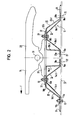
- Fig. 2 einen Schnitt nach der Linie II-II der Fig. 1.
- In den Fig. 1 und 2 ist eine Brückenkonstruktion 10 durch Längsträger des Sattelschleppers symbolisiert, welche mit Hilfsrahmenwinkeln versehen sein können.
- Auf der Brückenkonstruktion 10 ist eine Montageplatte befestigt, die ganz allgemein mit 12 bezeichnet ist. Die Montageplatte 12 ist von zwei in Fahrtrichtung F gemäß Fig. 2 hintereinanderliegenden inneren Hutprofilpaaren 14 und 16 gebildet. Die Hutprofile 14 und 16 jedes Hutprofilpaars erstrecken sich, wie aus Fig. 1 ersichtlich, quer zur Fahrtrichtung F jeweils nur über einen Teil der Quererstreckung der Brückenkonstruktion 10. über den inneren Hutprofilpaaren 14 und 16 sind zwei äußere Hutprofile 18 und 20 angeordnet, die äußeren Hutprofile 18 und 20 erstrecken sich, wie aus Fig. 1 ersichtlich, über die gesamte Breite der Brückenkonstruktion 10.
- Die inneren Hutprofile 14 und 16 weisen Basisflansche 14a und 16a, Scheitelteile 14b und 16b und Flanken 14c1, 14c bzw. 16c , 16c2 auf.
- Die äußeren Hutprofile 18 weisen Basisflansche 18a und 20a, Scheitelteile 18b und 20b, Flanken 18c1, 18c2 bzw. 20c1, 20c2 auf.
- Die Basisflansche 18a und 20a der äußeren Hutprofile 18, 20 liegen über den Basisflanschen 14a und 16a der inneren Hutprofile 14, 16 und sind gemeinsam mit diesen durch Befestigungsbolzen 22 an der Brückenkonstruktion 10 befestigt. Zur Erhöhung der Schubfestigkeit in Fahrtrichtung F sind an der Brückenkonstruktion 10 Anschläge 24 angeschweißt, welche mit den Enden der Basisflansche 14a, 16a und 18a, 20a in schubübertragendem Eingriff stehen.
- Die Scheitelteile 14b und 16b der inneren Hutprofile 14, 16 liegen an den Unterseiten der Scheitelteile 18b und 20b der äußeren Hutprofile 18, 20 an. Auf den Oberseiten der Scheitelteile 18b und 20b der äußeren Hutprofile 18, 20 liegen die Lagerböcke 26 der ganz allgemein mit 28 bezeichneten Sattelkupplung auf. Sie sind mit den Scheitelteilen 14b, 16b und 18b, 20b durch Schraubenbolzen 30 verbunden, so daß gleichzeitig mit der Befestigung der Lagerböcke 26 auch die Scheitelteile der inneren und der äußeren Hutprofile miteinander verbunden sind.
- Wie aus Fig. 2 zu ersehen, sind die Flanken 14c1 und 14c 2 des inneren Hutprofils 14 gegenüber den Flanken 18c1 und 18c2 des äußeren Hutprofils 18 geneigt. Das gleiche gilt für die Flanken des inneren Hutprofils 16 und des äußeren Hutprofils 20. Durch diese Neigung ergibt sich eine günstige Schubkraftübertragung in Fahrtrichtung F, die sich in Zug- und Druckbeanspruchungen der Flanken umsetzt. Die vertikalen Flanken 18c2 und 20c2 der äußeren Hutpro- file 18 und 20 sorgen für eine hohe Steifigkeit in vertikaler Richtung.
- Auf den Scheitelteilen 18b und 20b der Hutprofile 18, 20 sind L-förmige Anschläge 32 für die Lagerböcke 26 angebracht, welche der Schubaufnahme in horizontaler Längs-und Querrichtung dienen.
- Auf den Lagerböcken 26 ist die Sattelplatte 34 um eine Kippachse 36 kippbar gelagert.
Claims (11)
Priority Applications (1)
| Application Number | Priority Date | Filing Date | Title |
|---|---|---|---|
| AT81106173T ATE14097T1 (de) | 1980-09-04 | 1981-08-06 | Anordnung einer sattelkupplung auf einer brueckenkonstruktion eines sattelschleppers. |
Applications Claiming Priority (2)
| Application Number | Priority Date | Filing Date | Title |
|---|---|---|---|
| DE3033364A DE3033364C2 (de) | 1980-09-04 | 1980-09-04 | Anordnung einer Sattelkupplung auf einer Brückenkonstruktion eines Sattelschleppers |
| DE3033364 | 1980-09-04 |
Publications (3)
| Publication Number | Publication Date |
|---|---|
| EP0047400A2 true EP0047400A2 (de) | 1982-03-17 |
| EP0047400A3 EP0047400A3 (en) | 1983-08-17 |
| EP0047400B1 EP0047400B1 (de) | 1985-07-03 |
Family
ID=6111150
Family Applications (1)
| Application Number | Title | Priority Date | Filing Date |
|---|---|---|---|
| EP81106173A Expired EP0047400B1 (de) | 1980-09-04 | 1981-08-06 | Anordnung einer Sattelkupplung auf einer Brückenkonstruktion eines Sattelschleppers |
Country Status (3)
| Country | Link |
|---|---|
| EP (1) | EP0047400B1 (de) |
| AT (1) | ATE14097T1 (de) |
| DE (2) | DE3033364C2 (de) |
Cited By (5)
| Publication number | Priority date | Publication date | Assignee | Title |
|---|---|---|---|---|
| US4721323A (en) * | 1986-07-17 | 1988-01-26 | Masco Corporation Of Indiana | Fifth wheel hitch |
| GB2229983A (en) * | 1989-03-07 | 1990-10-10 | * Transport Equipment Components Ltd | A fifth wheel mounting structure |
| US7950152B2 (en) * | 2006-09-18 | 2011-05-31 | Jost-Werke Gmbh | Method of mounting a bearing block on a mounting plate |
| CN102658840A (zh) * | 2012-05-22 | 2012-09-12 | 中国重汽集团济南动力有限公司 | 一种牵引车新型鞍座 |
| WO2020226494A1 (en) * | 2019-05-06 | 2020-11-12 | Daf Trucks N.V. | A semitrailer towing vehicle comprising a fifth wheel assembly. |
Families Citing this family (3)
| Publication number | Priority date | Publication date | Assignee | Title |
|---|---|---|---|---|
| CH659625A5 (de) * | 1982-12-13 | 1987-02-13 | Fischer Ag Georg | Montageplatte fuer eine sattelkupplung. |
| DE4135288A1 (de) * | 1991-10-25 | 1993-04-29 | Rockinger Spezial Fab Joh | Sattelzugfahrzeug |
| DE4142363A1 (de) * | 1991-12-20 | 1993-06-24 | Rockinger Spezial Fab Joh | Anordnung einer sattelplattenbaugruppe auf einem tragrahmen eines zugfahrzeugs |
Family Cites Families (4)
| Publication number | Priority date | Publication date | Assignee | Title |
|---|---|---|---|---|
| CH219557A (de) * | 1941-04-19 | 1942-02-15 | Saurer Ag Adolph | Metallboden an Fahrgestellen für Personen-Fahrzeuge. |
| US2681236A (en) * | 1950-12-28 | 1954-06-15 | John N Apgar | Lower fifth wheel plate mounting |
| DE1097466B (de) * | 1958-05-10 | 1961-01-19 | Hoesch Ag | Staehlerner Fussboden aus C-Profilen, insbesondere fuer Schienen- und Strassenfahrzeuge |
| US3399907A (en) * | 1966-08-02 | 1968-09-03 | Gen Tire & Rubber Co | Elastomeric energy absorber |
-
1980
- 1980-09-04 DE DE3033364A patent/DE3033364C2/de not_active Expired
-
1981
- 1981-08-06 EP EP81106173A patent/EP0047400B1/de not_active Expired
- 1981-08-06 AT AT81106173T patent/ATE14097T1/de not_active IP Right Cessation
- 1981-08-06 DE DE8181106173T patent/DE3171205D1/de not_active Expired
Cited By (6)
| Publication number | Priority date | Publication date | Assignee | Title |
|---|---|---|---|---|
| US4721323A (en) * | 1986-07-17 | 1988-01-26 | Masco Corporation Of Indiana | Fifth wheel hitch |
| GB2229983A (en) * | 1989-03-07 | 1990-10-10 | * Transport Equipment Components Ltd | A fifth wheel mounting structure |
| US7950152B2 (en) * | 2006-09-18 | 2011-05-31 | Jost-Werke Gmbh | Method of mounting a bearing block on a mounting plate |
| CN102658840A (zh) * | 2012-05-22 | 2012-09-12 | 中国重汽集团济南动力有限公司 | 一种牵引车新型鞍座 |
| WO2020226494A1 (en) * | 2019-05-06 | 2020-11-12 | Daf Trucks N.V. | A semitrailer towing vehicle comprising a fifth wheel assembly. |
| NL2023076B1 (en) * | 2019-05-06 | 2020-11-30 | Daf Trucks Nv | A semitrailer towing vehicle comprising a fifth wheel assembly. |
Also Published As
| Publication number | Publication date |
|---|---|
| EP0047400B1 (de) | 1985-07-03 |
| EP0047400A3 (en) | 1983-08-17 |
| DE3033364A1 (de) | 1982-07-22 |
| ATE14097T1 (de) | 1985-07-15 |
| DE3171205D1 (en) | 1985-08-08 |
| DE3033364C2 (de) | 1983-03-03 |
Similar Documents
| Publication | Publication Date | Title |
|---|---|---|
| DE2702243C2 (de) | ||
| DE3114379A1 (de) | "aufbaustruktur eines personenkraftwagens" | |
| DE69903676T2 (de) | Rahmenanordnung | |
| EP0047400B1 (de) | Anordnung einer Sattelkupplung auf einer Brückenkonstruktion eines Sattelschleppers | |
| DE3150459A1 (de) | Foerderrinne fuer insbesondere kettenkratzfoerderer | |
| DE4244217A1 (de) | Selbsttragende Fahrzeugkarosserie | |
| EP1319584B1 (de) | Kippmulde für ein Transportfahrzeug | |
| DE10032663B4 (de) | Kraftwagen mit einer selbsttragenden Karosserie | |
| DE10045063B4 (de) | Fahrgestell mit einer Chassis-Baugruppe mit Federböcken für Straßenfahrzeuge | |
| DE2543729C2 (de) | Druckfester Tankcontainer | |
| DE9110124U1 (de) | Sattelanhänger | |
| EP0065623A1 (de) | Flanschkonstruktion für die Schraubverbindung zwischen einem Anhänger-Fahrgestell und dem Rahmen des Anhänger-Aufbaues | |
| EP0437655B1 (de) | Leiterrahmen | |
| DE19522341C2 (de) | Fahrzeugrahmen für ein Transportfahrzeug | |
| DE3506425A1 (de) | Schraegrampe | |
| DE894815C (de) | Verbindung des aus Leichtmetallprofiltraegern bestehenden Traggerippes mit der aus einem anderen Werkstoff bestehenden Aussenhaut von Wagenkasten, insbesondere fuer Kraftfahrzeuge | |
| DE8023631U1 (de) | Sattelschlepper mit Sattelkupplung | |
| EP0230493B1 (de) | Zugsattelzapfen-Aufnahmeteller | |
| DE102008005453B4 (de) | Dachkonstruktion für Kraftfahrzeug | |
| DE4325006C2 (de) | Verfahrbare Schrägrampe | |
| DE2340803A1 (de) | Pritschenunterbau fuer lastfahrzeuge, insbesondere lkw. | |
| DE2428600A1 (de) | Transportbehaelter | |
| EP1052163B1 (de) | Anhänger mit einem selbsttragenden Aufbau aus Leichtmetall | |
| EP4588725A1 (de) | Querträger | |
| EP0100750A2 (de) | Anordnung von Versteifungselementen, insbesondere für Ladeguttransportfahrzeuge |
Legal Events
| Date | Code | Title | Description |
|---|---|---|---|
| PUAI | Public reference made under article 153(3) epc to a published international application that has entered the european phase |
Free format text: ORIGINAL CODE: 0009012 |
|
| AK | Designated contracting states |
Designated state(s): AT BE CH DE FR GB IT LI LU NL SE |
|
| PUAL | Search report despatched |
Free format text: ORIGINAL CODE: 0009013 |
|
| AK | Designated contracting states |
Designated state(s): AT BE CH DE FR GB IT LI LU NL SE |
|
| 17P | Request for examination filed |
Effective date: 19830930 |
|
| GRAA | (expected) grant |
Free format text: ORIGINAL CODE: 0009210 |
|
| AK | Designated contracting states |
Designated state(s): AT BE CH DE FR GB IT LI LU NL SE |
|
| PG25 | Lapsed in a contracting state [announced via postgrant information from national office to epo] |
Ref country code: NL Effective date: 19850703 Ref country code: IT Free format text: LAPSE BECAUSE OF FAILURE TO SUBMIT A TRANSLATION OF THE DESCRIPTION OR TO PAY THE FEE WITHIN THE PRESCRIBED TIME-LIMIT;WARNING: LAPSES OF ITALIAN PATENTS WITH EFFECTIVE DATE BEFORE 2007 MAY HAVE OCCURRED AT ANY TIME BEFORE 2007. THE CORRECT EFFECTIVE DATE MAY BE DIFFERENT FROM THE ONE RECORDED. Effective date: 19850703 Ref country code: BE Effective date: 19850703 |
|
| REF | Corresponds to: |
Ref document number: 14097 Country of ref document: AT Date of ref document: 19850715 Kind code of ref document: T |
|
| PG25 | Lapsed in a contracting state [announced via postgrant information from national office to epo] |
Ref country code: SE Effective date: 19850730 |
|
| PG25 | Lapsed in a contracting state [announced via postgrant information from national office to epo] |
Ref country code: AT Effective date: 19850806 |
|
| REF | Corresponds to: |
Ref document number: 3171205 Country of ref document: DE Date of ref document: 19850808 |
|
| ET | Fr: translation filed | ||
| PG25 | Lapsed in a contracting state [announced via postgrant information from national office to epo] |
Ref country code: LU Free format text: LAPSE BECAUSE OF NON-PAYMENT OF DUE FEES Effective date: 19850831 |
|
| PG25 | Lapsed in a contracting state [announced via postgrant information from national office to epo] |
Ref country code: GB Effective date: 19850903 |
|
| NLV1 | Nl: lapsed or annulled due to failure to fulfill the requirements of art. 29p and 29m of the patents act | ||
| PLBI | Opposition filed |
Free format text: ORIGINAL CODE: 0009260 |
|
| GBPC | Gb: european patent ceased through non-payment of renewal fee | ||
| 26 | Opposition filed |
Opponent name: JOST-WERKE GMBH Effective date: 19860326 |
|
| RDAG | Patent revoked |
Free format text: ORIGINAL CODE: 0009271 |
|
| STAA | Information on the status of an ep patent application or granted ep patent |
Free format text: STATUS: PATENT REVOKED |
|
| 27W | Patent revoked |
Effective date: 19870122 |
|
| REG | Reference to a national code |
Ref country code: FR Ref legal event code: ST |