EP0047408A1 - Procédé pour vider, nettoyer et désinfecter des récipients hygiéniques dans le domaine hospitalier, sans contamination de la partie extérieure de l'appareil utilisé pour sa mise en oeuvre - Google Patents
Procédé pour vider, nettoyer et désinfecter des récipients hygiéniques dans le domaine hospitalier, sans contamination de la partie extérieure de l'appareil utilisé pour sa mise en oeuvre Download PDFInfo
- Publication number
- EP0047408A1 EP0047408A1 EP81106397A EP81106397A EP0047408A1 EP 0047408 A1 EP0047408 A1 EP 0047408A1 EP 81106397 A EP81106397 A EP 81106397A EP 81106397 A EP81106397 A EP 81106397A EP 0047408 A1 EP0047408 A1 EP 0047408A1
- Authority
- EP
- European Patent Office
- Prior art keywords
- water
- chamber
- door
- steam
- rinsing
- Prior art date
- Legal status (The legal status is an assumption and is not a legal conclusion. Google has not performed a legal analysis and makes no representation as to the accuracy of the status listed.)
- Granted
Links
Images


Classifications
-
- A—HUMAN NECESSITIES
- A61—MEDICAL OR VETERINARY SCIENCE; HYGIENE
- A61L—METHODS OR APPARATUS FOR STERILISING MATERIALS OR OBJECTS IN GENERAL; DISINFECTION, STERILISATION OR DEODORISATION OF AIR; CHEMICAL ASPECTS OF BANDAGES, DRESSINGS, ABSORBENT PADS OR SURGICAL ARTICLES; MATERIALS FOR BANDAGES, DRESSINGS, ABSORBENT PADS OR SURGICAL ARTICLES
- A61L2/00—Disinfection or sterilisation of materials or objects, in general; Accessories therefor
- A61L2/02—Disinfection or sterilisation of materials or objects, in general; Accessories therefor using physical processes
- A61L2/04—Heat
- A61L2/06—Hot gas
- A61L2/07—Steam
-
- A—HUMAN NECESSITIES
- A61—MEDICAL OR VETERINARY SCIENCE; HYGIENE
- A61G—TRANSPORT, PERSONAL CONVEYANCES, OR ACCOMMODATION SPECIALLY ADAPTED FOR PATIENTS OR DISABLED PERSONS; OPERATING TABLES OR CHAIRS; CHAIRS FOR DENTISTRY; FUNERAL DEVICES
- A61G9/00—Bed-pans, urinals or other sanitary devices for bed-ridden persons; Cleaning devices therefor, e.g. combined with toilet-urinals
- A61G9/02—Cleaning devices
-
- A—HUMAN NECESSITIES
- A61—MEDICAL OR VETERINARY SCIENCE; HYGIENE
- A61L—METHODS OR APPARATUS FOR STERILISING MATERIALS OR OBJECTS IN GENERAL; DISINFECTION, STERILISATION OR DEODORISATION OF AIR; CHEMICAL ASPECTS OF BANDAGES, DRESSINGS, ABSORBENT PADS OR SURGICAL ARTICLES; MATERIALS FOR BANDAGES, DRESSINGS, ABSORBENT PADS OR SURGICAL ARTICLES
- A61L2/00—Disinfection or sterilisation of materials or objects, in general; Accessories therefor
- A61L2/24—Apparatus using programmed or automatic operation
Definitions
- the object of the invention is to develop a method for emptying, cleaning and disinfecting hygiene vessels in the care sector without contaminating the outer device for carrying it out.
- This task has a high economic value, because its solution enables a health and hygienic removal of waste from the care sector.
- This state-of-the-art system should be mobile.
- the device of the invention is stationary and connected to the supply lines and the discharge line.
- a mixture of a disinfectant with water is to be injected into the bedpan under pressure.
- the method of the invention does not use disinfectants, but water and hot steam.
- the two phases of water are sufficient for the method of the invention since contamination of the device by touching with the hands is avoided.
- the method of the invention also rotates the devices placed in a closed washing compartment, but in such a way that splashing out of the liquid or solid contents is reliably avoided even with rapid rotation.
- the known method differs significantly from the method of the invention in that it is necessary to store the emptied bedpan over a longer period of time in a special dirty water tank.
- Another major disadvantage of the known method is that it requires a considerable dilution of the contents of the vessels to be cleaned, such as bed pans, which means that larger amounts of the liquid phase must be removed from the components.
- German Offenlegungsschrift 2938400 also requires a liquid disinfectant for the disinfection of hoses, pipes and the like, which is introduced under pressure into the cavity to be disinfected.
- the door of the washing compartment is then opened by pressing a button without touching the device with the hands to avoid contamination, while at the same time turning back the mounting bracket with the vessels to remove them and to repeat the process steps.
- “radiation-geometric” distribution of the pressurized water jet in stage 5 is understood to mean the division of the washing space into sectors by uniform spraying from the spray nozzles. This technical effect is the only way to achieve short-term, complete cleaning with the optimally small amount of water.
- What is essential for carrying out the method of the invention is the simultaneous condensation of the amount of steam entering and flowing through the washing chamber.
- the method of the invention allows the amount of steam introduced and the amount to be condensed to be condensed so that there is an internal equilibrium in the washing room, no overpressure occurs, the steam could lead through the sealing of the door to the outside, or no greater or even a negative pressure occurs which could suck in air from the outside through the sealing of the door to the inside.
- the residual condensation of steam vapors, the recooling of the rinsing chamber and the vessels to be removed can also be carried out as a process step using the same measures without an additional device.
- the method of the invention with the device for carrying it out offers the considerable advantage of rapid throughput of devices while avoiding contamination of the device or the cleaned devices, since the switches are not touched with the hands during insertion and removal.
- the method of the invention allows the object of the invention to be achieved for a short time with an optimally small amount of water and steam. No connections to special devices or ventilation or external condensation are required.
- the overall method with the device of the invention allows the sequence and the combination of the measures as technical effects to solve the problem of the invention as a "process” and device that works "in itself”.
- the method of the invention works with little investment, on the size and scope of the device and on energy consumption and on water and steam.
- the vessel contents are removed in a known manner without additional dilution.
- a device for rinsing and disinfecting bedpans and the like known from the Swiss patent specification 602 202 has a frame with a rinsing chamber which is connected to a drain at the bottom and has an opening at the top which can be closed with a sliding cover which can be moved horizontally by a motor.
- An annular channel with an outlet gap is present in the rinsing chamber under its upper edges.
- a number of spray nozzles are arranged distributed under the ring channel.
- the ring channel is connected to the cold water pressure line of the building or an external cistern via an electric valve.
- the spray nozzles are connected to the cold water and hot water pressure lines of the building via two electro valves.
- the washing chamber there is a gap between the latter and the cover, which connects the interior of the washing chamber to a steam condensation device arranged outside of it.
- This has a collecting channel provided with a drain and a tube running in it along one of the two upper longitudinal edges of the channel,. which is provided on its lower side with nozzle-like outlet openings.
- a caregiver places it in the washing chamber. Then the caregiver actuates a start switch that starts a program control unit.
- This control unit now controls the rest of the workflow, so that the sliding cover closes the washing chamber first.
- Cold water is then fed in through the annular gap in a pre-rinsing phase in order to wash away the coarse dirt particles.
- a cleaning phase a mixture of cold and warm water is sprayed through the spray nozzles during a certain time interval.
- hot water at a temperature of approximately 95 ° C is sprayed through the spray nozzles.
- the device known from the Swiss patent 602 202 has several disadvantages. For example, if a bedpan containing manure used by a patient is to be cleaned in a hospital, the caregiver must first tilt the bedpan manually and empty it into the washing chamber. There is a high probability that microorganisms and possibly even feces particles get on the skin or clothing of the caregiver and are carried off to other patients in this way. Another disadvantage of the device is that it takes up a relatively large amount of space in the floor plan. Since the lid of the washing chamber is displaced away from it in the horizontal direction when it is opened, the device must have a length measured in the sliding direction of the lid which is at least about two and a half to three times the washing chamber dimension measured in the same direction.
- the ring channel and the spray nozzles are connected by lines directly to the line network of the building, there is also the risk of contamination or microorganisms in the event of a backflow of water, for example during a line repair the rinsing chamber can get into the pipeline network of the building.
- the direct feeding of the ring channel and the spray nozzles from the pressurized water supply network also requires that the conduit pipes have relatively large cross-sections to avoid an excessive pressure drop. This is all the more the case because in modern hospitals there is a device for rinsing and disinfecting containers for every two to ten beds, so that under certain circumstances a larger number of such devices is used simultaneously.
- a rinsing chamber provided with spray nozzles has an opening located in the vertical front wall of the device. This can be closed with a door that can be pivoted manually about a horizontal pivot axis located at the lower opening edge. When opening, the door is pivoted into a position in which it projects horizontally outwards. The door is otherwise 'provided on its open top side with brackets on which bedpans and the like can be fixed.
- the apparatus further comprises angeord above the S p ülhunt a neten water tank, which is connected to the cold and hot water connection of the building via supply lines. The water tank is also connected to the spray nozzles by a pump.
- a container to be cleaned is fixed on an appropriately designed holder with the door open. Then the door is swung up manually to close the rinsing chamber, whereby the container is tilted and emptied.
- An automatically running work program is then started by pressing a button.
- cold water is pumped out of the tank and sprayed into the rinsing chamber through the spray nozzles.
- warm water is pumped to the spray nozzles by means of the pump and atomized through them. Disinfection then takes place, depending on the design of the device, this can be done with hot water, steam or by chemical means.
- the door for opening the rinsing chamber is folded outwards and then projects horizontally into the space surrounding the device.
- the device therefore takes up a relatively large amount of space when the door is open, which is a hindrance in many cases. This is particularly the case when such a device has to be installed in a corridor or other narrow passage. It is therefore often necessary in these devices to keep the door closed when the washing chamber is not in use, so that the nursing staff must first open the door to clean a container and then close it again after inserting the container into a holder. For example, if a caregiver wants to empty and clean a bedpan containing faeces, she has to touch the door at least once.
- the present invention has also set itself the task of creating a device that enables a caregiver to insert and empty a container containing fecal matter in a manner that ensures perfect hygiene in the rinsing chamber of the device.
- FIGs 1 and 2 the floor 1 and a wall 3 of the room of a building can be seen.
- a device 5 for rinsing and disinfecting containers stands on the floor 1 and is also attached to the wall 3.
- the device 5 has a frame 7 on which a vertical front wall 9 and two vertical side walls 11 are fastened, which together form a box.
- a cistern 13 is arranged in the lower part thereof and fastened to the frame 7 with fastening means which result in heat conduction which is as small as possible.
- the washing chamber 13 has a cuboid part at the top, to which a tapering part connects at the bottom, the lower end of which forms the outlet 13a of the washing chamber. This is connected to the drain pipe of the building via a siphon 15.
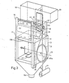
- the cuboid part of the rinsing chamber 13 is provided on its front side with an opening 13b which can be seen in FIG. This can be closed with a door 17, which is guided up and down in guides 19 along a vertical plane. In its lower end position, shown in FIGS. 1 and 2, the door closes the rinsing chamber 13 at least in a watertight and preferably somewhat steam-tight manner, while releasing it in its upper end position, shown in FIG. 3.
- a rope 21, only shown in FIG. 2 is fastened, which is deflected above the door at a deflection roller 23 and at its other end de a counterweight 25 is attached.
- the pivot axis 29 runs horizontally and parallel to the vertical plane along which the door 17 is displaceable.
- the holder 27, shown in a highly simplified manner, has means for holding at least one container, for example a bedpan and / or a urine bottle, in such a way that the container does not fall out even when the holder 27 is pivoted.
- the holder is expediently releasably connected to the shaft journals used for its storage, so that it can be replaced in a simple manner if this should be necessary, for example, due to the use of other containers.
- the bearings or bushings of the shaft journals in the rinsing chamber walls are sealed at least watertight.
- the bracket 25 is rotatably connected to a sprocket 31 arranged outside the rinsing chamber.
- Two other sprockets 33 and 35 are arranged at the upper and lower ends of a guide 19.
- An endless chain 41 is guided around the chain wheels 33, 35 and 37 in such a way that the chain wheel 31 also engages in them.
- the motor 37 and the sprocket 39 connected to it are movably held in the frame and loaded by a spring, not shown, so that the sprocket 39 tensions the chain 41.
- the chain 41 has a vertically extending section which is connected to the door 17 by at least one connecting element 43.
- the rinsing chamber 13 there are two water tanks 51 and 53 which abut against one another in a partition. As shown in Figure 4, the two tanks are closed at the top by a common ceiling. However, the partition mentioned does not reach the ceiling, or at least not everywhere.
- the filling levels of the tanks 51 and 53 below the upper partition edge are designated 61 and 63, respectively. There is a space between the filling levels and the ceiling. Even if the two tanks are filled up to their filling levels, an air-containing cavity is still present above the water levels, these two cavities being connected at the partition. The two connected cavities are connected to the environment by a small passage.
- the bottom of the water tank 51 is connected to a vertically downward flushing line 55, which opens into the interior of the flushing cistern 13 at its mouth 55a.
- the mouth 55a is located, for example, approximately at the transition between the cuboid and the tapered cistern part and is designed such that the water flowing out of it during the rinsing flows downward along the walls of the tapered rinsing chamber part.
- An electrically operable valve 57 is switched into the flushing line 55, as can be seen from FIG.
- a pipe serving as a steam condenser 59 leads vertically upward from the top wall of the washing chamber 13 into the water tank 51, the pipe mouth being above the filling level 61.
- the water tank 53 is connected at its bottom or in the vicinity thereof by a line 65 to the inlet of a pump 67 located below the water tank 53. Its outlet is connected by a line 69 to spray nozzles 71 provided in the rinsing chamber 13, which are only shown in FIG. 4 are shown schematically and are arranged such that they can generate water or steam jets which are directed at least in part against a container 83 held by the holder 27.
- the line 69 has a section 69a rising vertically from the outlet of the pump 67 up to the filling level 63.
- the line section 69b adjoining this, and located above the filling level 63, is through a ventilation line 73, into which an electrically actuable valve 75 is switched on, with the interior of the tank 53 lying above the filling level 63 connected.
- a horizontal downward section 69c connects to the horizontal line section 69b, from which branches 69d, 69e lead to the spray nozzles 71.
- a water evaporator 77 has a chamber 77a, into which an electric heating element 79 and a temperature sensor 81 protrude.
- the chamber 77a is arranged below the lowermost spray nozzles 71 and below the lowermost section 69e of the line 69 leading to the spray nozzles and is also connected to the line 69 by the lowermost section 69f thereof.
- the line 69 and the water evaporator 77 do not contain a valve or the like, so that the chamber 77a is continuously open connection is connected to the pump 67 and the spray nozzles 71 in all working phases.
- the water tank 51 is connected via an electrically actuable valve 85 to a cold water feed line 87, which is connected via a filter 89 and a tap 91 to a connection 93 of the cold water pressure line network of the building.
- the tank 51 is also provided with a level sensor 95.
- the water tank 53 is connected to the outlet of a mixing valve 97. This has two inputs, one of which also has an electrically operable valve 99 the cold water supply line 87 and the other is connected via an electrically actuable valve 101 to a hot water supply line 103 which is connected to a connection 105 of the hot water supply network of the building.
- the water tank 53 is provided with a level sensor 107.
- the rinsing chamber 13 is also provided with a temperature sensor 109.
- an electrical program control element 121 which is connected to a pushbutton switch 123.
- the latter is arranged on the front wall 11 of the device in such a way that its push button can be operated by one person with the elbow.
- lamps and pushbuttons which are designated in their entirety by 125 and are connected to the program control element 121.
- the program control element 121 is provided with the electronic circuits used to control and monitor the workflow, in particular timers and control circuits as well as contactors. There are also manually adjustable actuators to set certain time intervals and temperature setpoints.
- the door 17 When the device 5 is ready for operation, but is not currently being used to clean a container, the door 17 is in its upper end position in which it is Opening 13b of the washing chamber 13 releases. If a caregiver now wants to clean a container, for example a bedpan containing droppings used by a patient, he inserts this container into the holder 27, as shown for the container 83 in FIG. The caregiver then presses the elbow on the pushbutton of the pushbutton switch 123. This causes the program control element 121 to start the workflow.
- the motor 39 is started so that it moves the chain 41 and thereby on the one hand shifts the door 17 into its lower end position, in which it closes the rinsing chamber opening 13b, and on the other hand the holder 27 with the container held by it 83 pivoted about the pivot axis 29.
- the chain wheel 31 is dimensioned such that the holder 27 and the container 83 are pivoted through an angle of approximately 120 to 180 ° and the container 83 is emptied.
- the program control element 121 opens the valve 57.
- cold water now flows from the water tank 51 via the flushing line 55 into the flushing chamber and flushes it droppings tipped out of the container 83 through the siphon 15.
- the valve 57 is closed again.
- the flushing line 55 and the valve 57 are dimensioned such that the amount of water supplied per unit of time is large enough to flush the coarse dirt through the siphon. Depending on the diameter of the siphon used, a minimum flow of 1 to 2 1 / s is provided.
- the valve 85 is opened at the latest when the rinsing process has ended, so that the tank 51 is filled up to the fill level 61 a short time after the end of the spill phase.
- the program control element 121 also starts the pump 67 during a predetermined time interval. This time interval is 30 to 60 s, for example, and thus extends beyond the end of the rinsing phase.
- the pump 67 then pumps water from the tank 53 to the spray nozzles 71, which at least partially spray the water against the container 83. This will rinse and clean the container.
- the tank 53 is refilled via the electrically operable valves 99 and 101 and the mixing valve 97.
- the mixing valve 95 which has a thermo-mechanical control element, is designed such that the tank is refilled with a water mixture whose temperature is approximately 40 to 45 ° C.
- the water pumped out of the tank 53 at the start of the cleaning phase is at room temperature. During the refilling of the tank during the pumping process, the water temperature then rises to the aforementioned 40 to 45 ° C.
- the zersprühte of the Sp l ühdüsen water 71 thus has a maximum of 40 bi: 45 ° C amount and thus forming structure underlying the Koagulationstempera- of albumen temperature.
- the pump 67 generates a pressure that is substantially larger, al E, the pressure generated by the gravitational force due to the difference in height, so that the pumped from their water emerges at a speed from the spraying nozzles at the spray nozzles, which is substantially greater than that of the at Pre-rinsing water flowing out of the mouth 55a of the rinsing line 55, on the other hand, the amount of water conveyed by the pump 67 per unit of time is smaller than that when rinsing through the rinsing line 55 amount of water supplied per unit of time and is, for example, 0.5 to 1 / s.
- valve 75 During operation of the pump 67, the valve 75 is closed and blocks the line 73. However, if the control element 121 has switched the pump 67 off again at the end of the cleaning phase, it briefly actuates the valve 75 two tanks 53, 55 connected to cavities present above the current water levels, which, as already mentioned, are connected to the environment and are therefore under ambient pressure. When the valve 75 is opened, the line 69 is therefore vented at its uppermost section 69b. The water in the line section 69c then flows out through the spray nozzles to the level of the deepest spray nozzle. Since the water evaporator 77 is located below the lowermost spray nozzles, the lowermost part of the line 69 and in particular the water evaporator remain filled with water during the venting.
- the program control element 121 While the pump 67 pumps water to the spray nozzles, the program control element 121 already switches on the heating element 79. About half a minute after the pump has been switched off, the water in the evaporator 77 reaches boiling temperature and begins to evaporate and flow as steam through the spray nozzles into the rinsing chamber 13.
- the container 83 located in the rinsing chamber is disinfected by this steam.
- the temperature on the wash chamber wall or in the wash chamber is measured with the temperature sensor 109.
- the steam is supplied so long that the temperature measured by the temperature sensor 109 during a predetermined time interval Valls of, for example, 30 to 120 s has a predetermined minimum value, which is, for example, 83 to 90 ° C.
- the steam supplied in the disinfection phase can flow into the steam condenser 59. Since this is cooled by the cold water present in the tank 51, most of the steam that has flowed into the condenser 59 condenses and then falls back into the rinsing chamber as water drops. The remaining steam that flows out of the upper end of the condenser 59 then condenses at least for the most part in the two tanks 51 and 53, which are connected to each other for air and steam. If there is still an overpressure due to the steam supply in the two water tanks, this is compensated for by the aforementioned connection between the tanks and the environment.
- a caregiver can therefore clear and empty the one to be emptied Introduce the nigging container into the rinsing chamber and start the cleaning process without having to touch the door or any other part of the device 5 with her hands, which are often dirty at the time of cleaning a patient. Furthermore, the container attached to the holder 27, which is located in the interior of the washing chamber at all pivoting positions of the holder 27, is tipped over and emptied without dirt particles or microorganisms being able to get to the outside of the washing chamber or even to the person who holds the container in has inserted the rinsing chamber. This ensures the greatest possible hygiene.
- the lamps present on the front wall 11 each. displayed which work step is currently taking place. If, for example, the water evaporator should be overheated, this is determined by the temperature sensor 81, the course of the program is stopped and a fault is signaled by one of the indicator lamps.
- the counterweight 25 connected to the door 17 has approximately the same mass as this, so that the chain 41 is not or only slightly loaded by the mass of the door 17.
- the motor 37 therefore only has to have a comparatively small output and is in particular dimensioned in such a way that it stops if, for example, a person should still keep his arm or hand under the door when closing.
- the flushing chamber opening 13b and the door 17 are arranged on a vertical wall of the device, the upper side of the flushing chamber need not be accessible for normal use of the device.
- the water tanks can therefore be placed directly above the wash chamber.
- the door since the door can be moved vertically, the device only needs to be open both when the door is open and when it is closed relatively little space.
- the width measured parallel to the front wall 11 can be, for example, approximately 60 cm and the depth measured at right angles to this can be approximately 50 cm.
- the two water tanks 51 and 53 ensure that no water can flow back from the rinsing chamber into the water supply network of the building. Furthermore, they make it possible to use lines with a relatively small cross section for the feed water.
- the device can be modified and equipped in various ways.
- a non-pivoting grate or the like could also be present in the washing chamber, on which any objects can be arranged which need to be cleaned but not necessarily tilted.
Landscapes
- Health & Medical Sciences (AREA)
- Epidemiology (AREA)
- Life Sciences & Earth Sciences (AREA)
- Animal Behavior & Ethology (AREA)
- General Health & Medical Sciences (AREA)
- Public Health (AREA)
- Veterinary Medicine (AREA)
- Apparatus For Disinfection Or Sterilisation (AREA)
- Cleaning By Liquid Or Steam (AREA)
Priority Applications (1)
| Application Number | Priority Date | Filing Date | Title |
|---|---|---|---|
| AT81106397T ATE3136T1 (de) | 1980-08-19 | 1981-08-18 | Verfahren zum entleeren, reinigen, desinfektion von hygiene-gefaessen im pflegesektor ohne kontaminierung der aeusseren vorrichtung zu seiner durchfuehrung. |
Applications Claiming Priority (2)
| Application Number | Priority Date | Filing Date | Title |
|---|---|---|---|
| CH624880 | 1980-08-19 | ||
| CH6248/80 | 1980-08-19 |
Publications (2)
| Publication Number | Publication Date |
|---|---|
| EP0047408A1 true EP0047408A1 (fr) | 1982-03-17 |
| EP0047408B1 EP0047408B1 (fr) | 1983-04-27 |
Family
ID=4306600
Family Applications (1)
| Application Number | Title | Priority Date | Filing Date |
|---|---|---|---|
| EP81106397A Expired EP0047408B1 (fr) | 1980-08-19 | 1981-08-18 | Procédé pour vider, nettoyer et désinfecter des récipients hygiéniques dans le domaine hospitalier, sans contamination de la partie extérieure de l'appareil utilisé pour sa mise en oeuvre |
Country Status (3)
| Country | Link |
|---|---|
| EP (1) | EP0047408B1 (fr) |
| AT (1) | ATE3136T1 (fr) |
| DE (1) | DE3160204D1 (fr) |
Cited By (12)
| Publication number | Priority date | Publication date | Assignee | Title |
|---|---|---|---|---|
| EP0093846A1 (fr) * | 1982-03-15 | 1983-11-16 | S I C Ag | Procédé pour vider et laver automatiquement des récipients sanitaires et dispositif pour sa mise en oeuvre |
| EP0779110A3 (fr) * | 1995-12-11 | 1998-05-13 | GEA Till GmbH & Co. | Procédé de nettoyage des récipients |
| US5822344A (en) * | 1994-10-27 | 1998-10-13 | Carl-Zeiss-Stiftung | Process and arrangement for the excitation of a gas laser by means of a high voltage discharge |
| EP0879588A3 (fr) * | 1997-05-21 | 1999-07-14 | Discher Sanitätstechnik GmbH | Dispositif de rinçage et de désinfection de matériels sanitaires, comme bassins de lit, urinals ou similaires |
| EP0978267A3 (fr) * | 1998-08-03 | 2000-12-06 | BHT Hygiene Technik GmbH | Procédé et appareil pour nettoyer et désinfecter des récipients |
| WO2006119873A1 (fr) * | 2005-05-11 | 2006-11-16 | Meiko Maschinenbau Gmbh & Co. Kg | Procede et systeme pour preparer des recipients a excrements |
| CN111377174A (zh) * | 2020-02-26 | 2020-07-07 | 福建龙马环卫装备股份有限公司 | 适用于压缩式垃圾车的作业方法及控制系统 |
| CN111729108A (zh) * | 2020-06-24 | 2020-10-02 | 张沙沙 | 一种护理用消毒灭菌装置 |
| CN113520287A (zh) * | 2021-07-21 | 2021-10-22 | 郭超凡 | 消化科硬质内窥镜用智能清洗系统 |
| CN113893375A (zh) * | 2021-11-10 | 2022-01-07 | 沈阳北创医学检验所有限公司 | 一种移液器套筒内壁消毒装置 |
| EP4272769A1 (fr) * | 2022-05-03 | 2023-11-08 | Bonferraro S.p.A. | Machine pour le lavage et la thermodésinfection d'articles sanitaires équipée d'un dispositif pour la condensation de la vapeur provenant du réservoir de lavage |
| CN117399391A (zh) * | 2023-10-18 | 2024-01-16 | 麦克斯流体科技(江苏)有限公司 | 一种水冷式平衡器的清洁装置 |
Citations (2)
| Publication number | Priority date | Publication date | Assignee | Title |
|---|---|---|---|---|
| CH602202A5 (en) * | 1976-01-20 | 1978-07-31 | Sic Ag | Rinsing and disinfecting installation for hospital |
| DE2712020A1 (de) * | 1977-03-18 | 1978-09-21 | Muenchner Medizin Mechanik | Dekontaminationsanlage fuer chirurgische instrumente u.dgl. |
-
1981
- 1981-08-18 DE DE8181106397T patent/DE3160204D1/de not_active Expired
- 1981-08-18 EP EP81106397A patent/EP0047408B1/fr not_active Expired
- 1981-08-18 AT AT81106397T patent/ATE3136T1/de not_active IP Right Cessation
Patent Citations (2)
| Publication number | Priority date | Publication date | Assignee | Title |
|---|---|---|---|---|
| CH602202A5 (en) * | 1976-01-20 | 1978-07-31 | Sic Ag | Rinsing and disinfecting installation for hospital |
| DE2712020A1 (de) * | 1977-03-18 | 1978-09-21 | Muenchner Medizin Mechanik | Dekontaminationsanlage fuer chirurgische instrumente u.dgl. |
Cited By (13)
| Publication number | Priority date | Publication date | Assignee | Title |
|---|---|---|---|---|
| EP0093846A1 (fr) * | 1982-03-15 | 1983-11-16 | S I C Ag | Procédé pour vider et laver automatiquement des récipients sanitaires et dispositif pour sa mise en oeuvre |
| US5822344A (en) * | 1994-10-27 | 1998-10-13 | Carl-Zeiss-Stiftung | Process and arrangement for the excitation of a gas laser by means of a high voltage discharge |
| EP0779110A3 (fr) * | 1995-12-11 | 1998-05-13 | GEA Till GmbH & Co. | Procédé de nettoyage des récipients |
| EP0879588A3 (fr) * | 1997-05-21 | 1999-07-14 | Discher Sanitätstechnik GmbH | Dispositif de rinçage et de désinfection de matériels sanitaires, comme bassins de lit, urinals ou similaires |
| EP0978267A3 (fr) * | 1998-08-03 | 2000-12-06 | BHT Hygiene Technik GmbH | Procédé et appareil pour nettoyer et désinfecter des récipients |
| CN101170982B (zh) * | 2005-05-11 | 2010-06-23 | 迈科机械制造有限及两合公司 | 用于处理排泄物器皿的方法和系统 |
| WO2006119873A1 (fr) * | 2005-05-11 | 2006-11-16 | Meiko Maschinenbau Gmbh & Co. Kg | Procede et systeme pour preparer des recipients a excrements |
| CN111377174A (zh) * | 2020-02-26 | 2020-07-07 | 福建龙马环卫装备股份有限公司 | 适用于压缩式垃圾车的作业方法及控制系统 |
| CN111729108A (zh) * | 2020-06-24 | 2020-10-02 | 张沙沙 | 一种护理用消毒灭菌装置 |
| CN113520287A (zh) * | 2021-07-21 | 2021-10-22 | 郭超凡 | 消化科硬质内窥镜用智能清洗系统 |
| CN113893375A (zh) * | 2021-11-10 | 2022-01-07 | 沈阳北创医学检验所有限公司 | 一种移液器套筒内壁消毒装置 |
| EP4272769A1 (fr) * | 2022-05-03 | 2023-11-08 | Bonferraro S.p.A. | Machine pour le lavage et la thermodésinfection d'articles sanitaires équipée d'un dispositif pour la condensation de la vapeur provenant du réservoir de lavage |
| CN117399391A (zh) * | 2023-10-18 | 2024-01-16 | 麦克斯流体科技(江苏)有限公司 | 一种水冷式平衡器的清洁装置 |
Also Published As
| Publication number | Publication date |
|---|---|
| EP0047408B1 (fr) | 1983-04-27 |
| DE3160204D1 (en) | 1983-06-01 |
| ATE3136T1 (de) | 1983-05-15 |
Similar Documents
| Publication | Publication Date | Title |
|---|---|---|
| DE4142089C2 (de) | Vorrichtung zum Entsorgen von Körperausscheidungen im medizinischen Bereich | |
| EP4281708B1 (fr) | Appareil de cuisson pour cuisine professionnelle doté d'un dispositif d'aspiration de graisse, et procédé pour faire fonctionner un tel appareil de cuisson à aspiration de graisse | |
| EP1767226B1 (fr) | Dispositif pour le nettoyage, la désinfection à la vapeur et le refroidissement d'articles | |
| DE10134005C2 (de) | Deckel für Gargerät mit Reinigungsvorrichtung sowie Reinigungsverfahren | |
| DE2626396C2 (de) | Verfahren zur Behandlung von Tierexkrementen und Vorrichtung zur Durchführung des Verfahrens | |
| EP0047408B1 (fr) | Procédé pour vider, nettoyer et désinfecter des récipients hygiéniques dans le domaine hospitalier, sans contamination de la partie extérieure de l'appareil utilisé pour sa mise en oeuvre | |
| DE3877928T2 (de) | Einrichtung zum auffangen und zur abfuhr von waehrend der sterilisation aus zahnaerztlichen instrumenten ausfliessenden verunreinigten fluessigkeiten und zur haltung der instrumente waehrend solcher operationen. | |
| DE3232057A1 (de) | Reinigungsmaschine fuer waesche, geschirr od. dgl. | |
| WO2018149427A1 (fr) | Système de lavage et de nettoyage et procédé de lavage pour toilettes | |
| DE19509877C2 (de) | Vorrichtung zum Reinigen und Desinfizieren von Steckbecken, Urinflaschen und dgl. | |
| EP0093846B1 (fr) | Procédé pour vider et laver automatiquement des récipients sanitaires et dispositif pour sa mise en oeuvre | |
| DE19838180C2 (de) | Verfahren und Vorrichtung zum Reinigen und Desinfizieren von Gefäßen | |
| WO2016059129A2 (fr) | Procédé et dispositif pour le nettoyage de fours de cuisson | |
| DE19514467A1 (de) | Verfahren und Vorrichtung zum Reinigen und Desinfizieren von Verunreinigungen enthaltenden Behältern, insbesondere von Urinbeuteln | |
| DE202012002701U1 (de) | Gerät zum Spülen chirurgischer Instrumente | |
| DE10033479A1 (de) | Wasserspareinrichtung mit Pumpe für Sanitärduschen | |
| DE102010006448B4 (de) | Reinigungs- und Desinfektionsgerät für Pflegegeschirr und Verfahren zur Reinigung und Desinfektion von Pflegegeschirr | |
| DE2924050C2 (de) | Verfahren und Einrichtung zur Reinigung und Desinfektion von Transportbehältern | |
| DE8122304U1 (de) | "Vorrichtung zum Spülen und Desinfizieren" | |
| CH680341A5 (fr) | ||
| EP0670708B1 (fr) | Dispositif pour le lavage et/ou la desinfection d'ustensiles de soin | |
| DE9412825U1 (de) | Vorrichtung zur Herstellung von Scherbeneis | |
| DE3709020A1 (de) | Wasch- und spuelapparat | |
| DE2262685A1 (de) | Flaschenreinigungsmaschine | |
| DE2736024B1 (de) | Trockenklosett |
Legal Events
| Date | Code | Title | Description |
|---|---|---|---|
| PUAI | Public reference made under article 153(3) epc to a published international application that has entered the european phase |
Free format text: ORIGINAL CODE: 0009012 |
|
| AK | Designated contracting states |
Designated state(s): AT CH DE FR GB IT NL SE |
|
| 17P | Request for examination filed |
Effective date: 19820416 |
|
| GRAA | (expected) grant |
Free format text: ORIGINAL CODE: 0009210 |
|
| AK | Designated contracting states |
Designated state(s): AT CH DE FR GB IT LI NL SE |
|
| PG25 | Lapsed in a contracting state [announced via postgrant information from national office to epo] |
Ref country code: SE Free format text: THE PATENT HAS BEEN ANNULLED BY A DECISION OF A NATIONAL AUTHORITY Effective date: 19830427 Ref country code: NL Effective date: 19830427 Ref country code: IT Free format text: LAPSE BECAUSE OF FAILURE TO SUBMIT A TRANSLATION OF THE DESCRIPTION OR TO PAY THE FEE WITHIN THE PRESCRIBED TIME-LIMIT;WARNING: LAPSES OF ITALIAN PATENTS WITH EFFECTIVE DATE BEFORE 2007 MAY HAVE OCCURRED AT ANY TIME BEFORE 2007. THE CORRECT EFFECTIVE DATE MAY BE DIFFERENT FROM THE ONE RECORDED. Effective date: 19830427 Ref country code: FR Free format text: THE PATENT HAS BEEN ANNULLED BY A DECISION OF A NATIONAL AUTHORITY Effective date: 19830427 |
|
| REF | Corresponds to: |
Ref document number: 3136 Country of ref document: AT Date of ref document: 19830515 Kind code of ref document: T |
|
| REF | Corresponds to: |
Ref document number: 3160204 Country of ref document: DE Date of ref document: 19830601 |
|
| NLV1 | Nl: lapsed or annulled due to failure to fulfill the requirements of art. 29p and 29m of the patents act | ||
| ET | Fr: translation filed | ||
| PGFP | Annual fee paid to national office [announced via postgrant information from national office to epo] |
Ref country code: AT Payment date: 19890821 Year of fee payment: 9 |
|
| PGFP | Annual fee paid to national office [announced via postgrant information from national office to epo] |
Ref country code: GB Payment date: 19890831 Year of fee payment: 9 |
|
| PG25 | Lapsed in a contracting state [announced via postgrant information from national office to epo] |
Ref country code: GB Effective date: 19900818 Ref country code: AT Effective date: 19900818 |
|
| PGFP | Annual fee paid to national office [announced via postgrant information from national office to epo] |
Ref country code: DE Payment date: 19910128 Year of fee payment: 10 |
|
| GBPC | Gb: european patent ceased through non-payment of renewal fee | ||
| PG25 | Lapsed in a contracting state [announced via postgrant information from national office to epo] |
Ref country code: DE Effective date: 19920501 |
|
| PGFP | Annual fee paid to national office [announced via postgrant information from national office to epo] |
Ref country code: CH Payment date: 19930803 Year of fee payment: 13 |
|
| PG25 | Lapsed in a contracting state [announced via postgrant information from national office to epo] |
Ref country code: LI Effective date: 19940831 Ref country code: CH Effective date: 19940831 |
|
| REG | Reference to a national code |
Ref country code: CH Ref legal event code: PL |
|
| PLBE | No opposition filed within time limit |
Free format text: ORIGINAL CODE: 0009261 |
|
| STAA | Information on the status of an ep patent application or granted ep patent |
Free format text: STATUS: NO OPPOSITION FILED WITHIN TIME LIMIT |