EP0047567A2 - Werkzeughaltermontage und Spannzange - Google Patents
Werkzeughaltermontage und Spannzange Download PDFInfo
- Publication number
- EP0047567A2 EP0047567A2 EP81201258A EP81201258A EP0047567A2 EP 0047567 A2 EP0047567 A2 EP 0047567A2 EP 81201258 A EP81201258 A EP 81201258A EP 81201258 A EP81201258 A EP 81201258A EP 0047567 A2 EP0047567 A2 EP 0047567A2
- Authority
- EP
- European Patent Office
- Prior art keywords
- collet
- tool
- chuck
- chuck body
- bore
- Prior art date
- Legal status (The legal status is an assumption and is not a legal conclusion. Google has not performed a legal analysis and makes no representation as to the accuracy of the status listed.)
- Ceased
Links
Images
Classifications
-
- B—PERFORMING OPERATIONS; TRANSPORTING
- B23—MACHINE TOOLS; METAL-WORKING NOT OTHERWISE PROVIDED FOR
- B23B—TURNING; BORING
- B23B31/00—Chucks; Expansion mandrels; Adaptations thereof for remote control
- B23B31/02—Chucks
- B23B31/10—Chucks characterised by the retaining or gripping devices or their immediate operating means
- B23B31/12—Chucks with simultaneously-acting jaws, whether or not also individually adjustable
- B23B31/20—Longitudinally-split sleeves, e.g. collet chucks
- B23B31/201—Characterized by features relating primarily to remote control of the gripping means
- B23B31/202—Details of the jaws
-
- B—PERFORMING OPERATIONS; TRANSPORTING
- B23—MACHINE TOOLS; METAL-WORKING NOT OTHERWISE PROVIDED FOR
- B23B—TURNING; BORING
- B23B31/00—Chucks; Expansion mandrels; Adaptations thereof for remote control
- B23B31/02—Chucks
- B23B31/10—Chucks characterised by the retaining or gripping devices or their immediate operating means
- B23B31/107—Retention by laterally-acting detents, e.g. pins, screws, wedges; Retention by loose elements, e.g. balls
- B23B31/1072—Retention by axially or circumferentially oriented cylindrical elements
-
- B—PERFORMING OPERATIONS; TRANSPORTING
- B23—MACHINE TOOLS; METAL-WORKING NOT OTHERWISE PROVIDED FOR
- B23B—TURNING; BORING
- B23B31/00—Chucks; Expansion mandrels; Adaptations thereof for remote control
- B23B31/02—Chucks
- B23B31/10—Chucks characterised by the retaining or gripping devices or their immediate operating means
- B23B31/107—Retention by laterally-acting detents, e.g. pins, screws, wedges; Retention by loose elements, e.g. balls
- B23B31/10741—Retention by substantially radially oriented pins
-
- B—PERFORMING OPERATIONS; TRANSPORTING
- B23—MACHINE TOOLS; METAL-WORKING NOT OTHERWISE PROVIDED FOR
- B23B—TURNING; BORING
- B23B2231/00—Details of chucks, toolholder shanks or tool shanks
- B23B2231/20—Collet chucks
- B23B2231/2005—Keys preventing rotation
-
- Y—GENERAL TAGGING OF NEW TECHNOLOGICAL DEVELOPMENTS; GENERAL TAGGING OF CROSS-SECTIONAL TECHNOLOGIES SPANNING OVER SEVERAL SECTIONS OF THE IPC; TECHNICAL SUBJECTS COVERED BY FORMER USPC CROSS-REFERENCE ART COLLECTIONS [XRACs] AND DIGESTS
- Y10—TECHNICAL SUBJECTS COVERED BY FORMER USPC
- Y10T—TECHNICAL SUBJECTS COVERED BY FORMER US CLASSIFICATION
- Y10T279/00—Chucks or sockets
- Y10T279/17—Socket type
- Y10T279/17411—Spring biased jaws
- Y10T279/17529—Fixed cam and moving jaws
- Y10T279/17538—Threaded-sleeve actuator
-
- Y—GENERAL TAGGING OF NEW TECHNOLOGICAL DEVELOPMENTS; GENERAL TAGGING OF CROSS-SECTIONAL TECHNOLOGIES SPANNING OVER SEVERAL SECTIONS OF THE IPC; TECHNICAL SUBJECTS COVERED BY FORMER USPC CROSS-REFERENCE ART COLLECTIONS [XRACs] AND DIGESTS
- Y10—TECHNICAL SUBJECTS COVERED BY FORMER USPC
- Y10T—TECHNICAL SUBJECTS COVERED BY FORMER US CLASSIFICATION
- Y10T279/00—Chucks or sockets
- Y10T279/17—Socket type
- Y10T279/17564—Loose jaws
- Y10T279/17598—Fixed cam and moving jaws
- Y10T279/17606—Threaded sleeve and body
-
- Y—GENERAL TAGGING OF NEW TECHNOLOGICAL DEVELOPMENTS; GENERAL TAGGING OF CROSS-SECTIONAL TECHNOLOGIES SPANNING OVER SEVERAL SECTIONS OF THE IPC; TECHNICAL SUBJECTS COVERED BY FORMER USPC CROSS-REFERENCE ART COLLECTIONS [XRACs] AND DIGESTS
- Y10—TECHNICAL SUBJECTS COVERED BY FORMER USPC
- Y10T—TECHNICAL SUBJECTS COVERED BY FORMER US CLASSIFICATION
- Y10T279/00—Chucks or sockets
- Y10T279/17—Socket type
- Y10T279/17761—Side detent
- Y10T279/17821—Set screw
-
- Y—GENERAL TAGGING OF NEW TECHNOLOGICAL DEVELOPMENTS; GENERAL TAGGING OF CROSS-SECTIONAL TECHNOLOGIES SPANNING OVER SEVERAL SECTIONS OF THE IPC; TECHNICAL SUBJECTS COVERED BY FORMER USPC CROSS-REFERENCE ART COLLECTIONS [XRACs] AND DIGESTS
- Y10—TECHNICAL SUBJECTS COVERED BY FORMER USPC
- Y10T—TECHNICAL SUBJECTS COVERED BY FORMER US CLASSIFICATION
- Y10T409/00—Gear cutting, milling, or planing
- Y10T409/30—Milling
- Y10T409/309352—Cutter spindle or spindle support
- Y10T409/309408—Cutter spindle or spindle support with cutter holder
-
- Y—GENERAL TAGGING OF NEW TECHNOLOGICAL DEVELOPMENTS; GENERAL TAGGING OF CROSS-SECTIONAL TECHNOLOGIES SPANNING OVER SEVERAL SECTIONS OF THE IPC; TECHNICAL SUBJECTS COVERED BY FORMER USPC CROSS-REFERENCE ART COLLECTIONS [XRACs] AND DIGESTS
- Y10—TECHNICAL SUBJECTS COVERED BY FORMER USPC
- Y10T—TECHNICAL SUBJECTS COVERED BY FORMER US CLASSIFICATION
- Y10T409/00—Gear cutting, milling, or planing
- Y10T409/30—Milling
- Y10T409/30952—Milling with cutter holder
Definitions
- the present application is a divisional application of European Patent Application No. 80400019.8 published under No. 0 013 646 (A1). It is also related to European Patent Application No. 80400018.0 published under No. 0 013 645 (A1).
- the present invention relates to machine tools generally and, more specifically, to holding assemblies for retaining large cutting tools during machining in industrial applications.
- the present invention has particular application to chuck assemblies or holders for retaining large (7/8 inch diameter shank and larger) end mill tools.
- the present invention is also relevant to the holders for other precision cutting tools which develop high rotational torques during machining.
- the prior art tool holders for such tools has suggested two divergent generic approaches to the problem, neither of which is entirely satisfactory.
- the first approach uses a collet and chuck assembly, with the tool and collet held in place within the chuck body by frictional forces resulting from tightening of a collet nut.
- This approach provides the desired centering ability through the collet action but has a limited resistance to rotational forces, since the collet may be rotated within the chuck (and the tool shank within the collet) by a rather low rotational force.
- the other generic approach eliminates the collet altogether and provides a mounting of the tool to the chuck through the provision of one or more set screws within the chuck and used with or without special- made grooves in the tool shank. This approach is undesirable because the special tool shank grooves require customizing of each tool. Also, the lack of a collet in this assembly eliminates two advantages of a collet : a convenient and quick way of eliminating the clearance necessary for tool insertion ; and centering device within the chuck. Both of these advantages of a collet enable precision machining by the entire machine and, therefor, the assemblies without a collet have inherent limitations regarding the precision (or tolerances) to which the machining can be held.
- the tool must be positioned within a precise rotational orientation which may be troublesome, difficult or time consuming.
- a chuck assembly and collet for retaining a tool comprising a chuck body having an outer surface, and internal, rearwardly tapering bore and a radial aperture extending through the body between the outer surface and the bore, a collet mounted within the tapering bore of the chuck body, said collet including a tool receiving bore and means for positively securing a tool mounted within the receiving bore against axial pullout therefrom, characterized in that said collet includes an aperture extending therethrough into the receiving bore and aligned with the radial aperture of the chuck body ; and securing means for securing the chuck body to a tool mounted within the tool receiving bore of the collet, said securing means being mounted to said chuck body and extending through the aligned radial apertures in said chuck body and collet.
- the present invention provides a tool holding apparatus, for precision machining with standard, conmercially-available large-diameter end mill (or similar) tools.
- the present invention has, as one feature, a high resistance to axial pullout and improved resistance to rotational forces.
- the chuck assembly of the present invention also features a chuck assembly, collet and tool holder which when fully assembled, exhibits characteristics (resistance to cutting forces) as if it were a single solid piece, rather than three separate pieces.
- the present invention has the advantage that it uses standard, commercially-available tools, without requiring expensive and time- consuming customizing of the tool shanks.
- the assembly of the present invention also has the advantage that tools may be quickly and easily inserted, removed and changed.
- a further advantage of the present invention is that the shank of the tool need not be precisely oriented radially with respect to the chuck assembly in order to be properly secured.
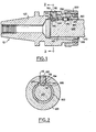
- FIG. 1 is a cross-sectional view of a chuck assembly 10 of the present invention.
- the chuck assembly 10 includes a chuck or collet holder 100 and a lock nut 200 and has a cutting tool 400, such as an end mill, extending from a front end 12 of the chuck assembly.
- a rear end of the chuck assembly is configured and dimensioned to be inserted into a conventional machine tool spindle (not shown) which drives the chuck assembly 10 and tool 400 for machining.
- a collet 300 includes a locking pin 380 and snap ring 390 mounted in a radial aperture 370, all as described more fully in the referenced parent application.
- the collet 300 of the present invention differs from that depicted and described in the parent application, in that a second radial aperture 375 extends through the collet 300 from its outer surface 330 into its bore 360. The radial aperture extends to the rear end of the collets.
- the tool 400 has a forward cutting portion 410 and a rear shank portion 420, which has a first beveled flat portion 430 and an additional flat portion 440.
- the additional flat portion 440 is common on commercially available larger diameter end mill tools.
- the screw 150 is a "ball clamp screw” type having a hemispherical recess 152 at its lower end into which a ball 154 is mounted.
- the ball 154 has a flat surface 156 for engaging the additional flat 440.
- the ball 154 is free to rotate within the screw recess 152 to accomodate a radial misalignment of the flat 440 by up to approximately 12° with respect to the aperture 115 without making a poor mechanical connection therewith.
- the screw 150 has external threads which engage complementary threads on the aperture 115.
- the tool 440 When the screw 150 is tightened to form a good seat of the flat ball surface 156 on the flat 440, the tool 440 is solidly coupled to the collet holder 100 and will not turn with respect to the tool holder without a failure of the ballclamp screw 150.
- FIG. 2 illustrates a cross-sectional view of the ballclamp screw 150 and its engagement of the rear flat 440 on the tool 400.
- the screw 150 is screwed down, through the threaded aperture 115 to clamp the flat part 156 of the ball 154 on the flat 440.
- the ball is free to rotate and does rotate to achieve maximum alignment between the flat surfaces 156, 440 as the rotational forces are applied to the screw 150.
- the collet 300 and its slots 305 and its rear aperture 375 are shown in this view.
- the rear aperture 375 in the collet is merely a window, or communicating link, through which the shank of the ballclamp screw 150 passes and the aperture 375 itself has no threads or other involvement with the screw 150.
Landscapes
- Engineering & Computer Science (AREA)
- Mechanical Engineering (AREA)
- Gripping On Spindles (AREA)
Applications Claiming Priority (2)
| Application Number | Priority Date | Filing Date | Title |
|---|---|---|---|
| US2118 | 1979-01-09 | ||
| US06/002,118 US4266895A (en) | 1979-01-09 | 1979-01-09 | High torque chuck assembly and collet |
Related Parent Applications (2)
| Application Number | Title | Priority Date | Filing Date |
|---|---|---|---|
| EP80400019.8 Division | 1980-01-08 | ||
| EP80400019A Division EP0013646B1 (de) | 1979-01-09 | 1980-01-08 | Spannzange und Spannfutter-Zusammenbau |
Publications (2)
| Publication Number | Publication Date |
|---|---|
| EP0047567A2 true EP0047567A2 (de) | 1982-03-17 |
| EP0047567A3 EP0047567A3 (de) | 1983-02-16 |
Family
ID=21699310
Family Applications (1)
| Application Number | Title | Priority Date | Filing Date |
|---|---|---|---|
| EP81201258A Ceased EP0047567A3 (de) | 1979-01-09 | 1980-01-08 | Werkzeughaltermontage und Spannzange |
Country Status (3)
| Country | Link |
|---|---|
| US (1) | US4266895A (de) |
| EP (1) | EP0047567A3 (de) |
| CA (1) | CA1131896A (de) |
Families Citing this family (14)
| Publication number | Priority date | Publication date | Assignee | Title |
|---|---|---|---|---|
| CH656334A5 (de) * | 1982-06-28 | 1986-06-30 | Kaiser Heinz Ag | Ausdrehwerkzeug. |
| US4550476A (en) * | 1983-02-18 | 1985-11-05 | Textron Inc. | Adjustment means for a driver bit |
| EP0157890A1 (de) * | 1984-04-07 | 1985-10-16 | Cad-Engineering Rupperswil AG | Schneidwerkzeug aus einem Schneidkopf und einem mit diesem verbundenen Aufnahmeschaft |
| DE9115854U1 (de) * | 1991-12-20 | 1992-02-20 | Otto Bilz, Werkzeugfabrik Gmbh & Co, 7302 Ostfildern | Spannfutter für Werkzeuge, Werkstücke o. dgl. |
| AU2002326946A1 (en) * | 2001-09-17 | 2003-04-01 | Milwaukee Electric Tool Corporation | Rotary hammer |
| DE10309015A1 (de) * | 2003-03-01 | 2004-09-16 | Wagner-Werkzeugsysteme Müller GmbH | Werkzeugschrumpfaufnahme |
| US8061718B2 (en) * | 2007-07-27 | 2011-11-22 | Robert Bosch Gmbh | Toolless bitholder for spiral saws |
| DE102009060678B4 (de) | 2009-12-28 | 2015-06-25 | Wto Werkzeug-Einrichtungen Gmbh | Werkzeugträger mit einer Spannzangenaufnahme und Werkzeugeinsatz zur Verwendung in einem Werkzeugträger |
| DE102010032284A1 (de) * | 2010-07-26 | 2012-01-26 | Rainer Pfister | Hydrodehnspannfutter |
| CN104245195B (zh) * | 2012-02-20 | 2017-12-19 | 安卡有限公司 | 夹头适配器 |
| EP2857127B1 (de) * | 2013-10-02 | 2016-03-16 | Eugen Fahrion GmbH & Co. KG | Werkzeughalter mit einer mit einem Werkzeug verspannbaren Spannzange |
| US10502001B2 (en) * | 2014-05-07 | 2019-12-10 | Baker Hughes, A Ge Company, Llc | Earth-boring tools carrying formation-engaging structures |
| JP6980261B2 (ja) * | 2017-09-26 | 2021-12-15 | エヌティーツール株式会社 | 工具保持具 |
| WO2020043283A1 (fr) * | 2018-08-29 | 2020-03-05 | Wibemo S.A. | Pince a tete interchangeable et outil la comportant |
Family Cites Families (4)
| Publication number | Priority date | Publication date | Assignee | Title |
|---|---|---|---|---|
| US3586344A (en) * | 1968-06-11 | 1971-06-22 | Omark Winslow Co | Quick-change tool assembly |
| US3762731A (en) * | 1971-06-21 | 1973-10-02 | M Matsumoto | Chuck for tool |
| US3811694A (en) * | 1972-05-31 | 1974-05-21 | Houdaille Industries Inc | Collet chuck |
| DE2802791A1 (de) * | 1978-01-23 | 1979-07-26 | Niedecker Herbert | Vorrichtung zum bestimmen und spannen von werkstuecken |
-
1979
- 1979-01-09 US US06/002,118 patent/US4266895A/en not_active Expired - Lifetime
-
1980
- 1980-01-03 CA CA343,009A patent/CA1131896A/en not_active Expired
- 1980-01-08 EP EP81201258A patent/EP0047567A3/de not_active Ceased
Also Published As
| Publication number | Publication date |
|---|---|
| US4266895A (en) | 1981-05-12 |
| EP0047567A3 (de) | 1983-02-16 |
| CA1131896A (en) | 1982-09-21 |
Similar Documents
| Publication | Publication Date | Title |
|---|---|---|
| US4934883A (en) | Tool assembly | |
| US4266895A (en) | High torque chuck assembly and collet | |
| US4714389A (en) | Tool holder | |
| US4377292A (en) | Chuck assembly and collet | |
| US8322258B2 (en) | Tool holder | |
| US8312615B2 (en) | Toolholder connector and associated system | |
| US4437801A (en) | High torque chuck assembly and collet | |
| US4647052A (en) | Tool-holding device and tool support | |
| EP2001624B1 (de) | Spannfutter und gegenstand mit paarungsfunktionen zum verhindern von axialem schlupf | |
| MX2007002780A (es) | Portaherramientas e inserto cortante para una instalación de portaherarmientas. | |
| EP0504165B1 (de) | Radialer positionsmechanismus für eine werkzeughalteranordnung | |
| CA1082904A (en) | Self-locking chuck | |
| CA2374223C (en) | Machining tool | |
| JPS6333961B2 (de) | ||
| GB2174322A (en) | Milling cutter | |
| JP3356282B2 (ja) | フライス工具のシヤンク | |
| JPH0431812B2 (de) | ||
| US5011346A (en) | Mounting device with conical shank | |
| WO2023223308A1 (en) | Tool holder having a cylindrical fixation bore extending rearwardly from a front fixation surface and a fastening bore intersecting the front fixation surface | |
| US6966728B1 (en) | Toolholder assembly | |
| US5882015A (en) | Floating toolholder | |
| CA1291649C (en) | Tool coupling | |
| US5758883A (en) | Differential thread collet actuation | |
| US4341006A (en) | Chuck assembly and collet | |
| US11097352B2 (en) | Device for the quick change of tool holder adapters |
Legal Events
| Date | Code | Title | Description |
|---|---|---|---|
| PUAI | Public reference made under article 153(3) epc to a published international application that has entered the european phase |
Free format text: ORIGINAL CODE: 0009012 |
|
| 17P | Request for examination filed |
Effective date: 19811126 |
|
| AC | Divisional application: reference to earlier application |
Ref document number: 13646 Country of ref document: EP |
|
| AK | Designated contracting states |
Designated state(s): DE FR GB |
|
| PUAL | Search report despatched |
Free format text: ORIGINAL CODE: 0009013 |
|
| AK | Designated contracting states |
Designated state(s): DE FR GB |
|
| STAA | Information on the status of an ep patent application or granted ep patent |
Free format text: STATUS: THE APPLICATION HAS BEEN REFUSED |
|
| 18R | Application refused |
Effective date: 19850311 |
|
| RIN1 | Information on inventor provided before grant (corrected) |
Inventor name: LEWIS, DAVID LEROY |